1999 HONDA CR-V Adiustment
[x] Cancel search: AdiustmentPage 440 of 1395

Manual Transmission
Diff€rential
lndex ...................... ......... 13-38
Backlash Inspestion ..,....,.,.....................,......, 13-38
Final Driven Gear Replacement .................... 13-39
Tapered Roller BearingReplacement ............. 13-39
Bearing Outer Race Replacement ......,.,........ 13-i10
Tapered Roller Bearing PreloadAdiustment ............... 13-il1
Oil Seal Reolacement .................................... 13-/l:}
Transfer Assembly
lllustrated Index ............. 13-il4
Inspection ..,....,.,......,...... 13-46
Disassembly ................... 13-47
Transfer Drive Gear BearingReplacement ...,..................,....................... 13-ilg
Transfer Driven Gear Shaft BearingReplacement .............................................. 13-ilg
Transfer Shaft Disassembly/Reassembly .............. 13-50
Transler Cover A Bearing Outer RaceRep1acement.........,.,.,..........,....,...,.........,., 13-50
Transter Housing Bearing Outer RaceReD1acement.............................................. 13-51
Reassembly ..-............,... 13-52
Mainshaft Bearing/Oil Seal
Beplacement .................. 13-62
Countershaft Bearing
Replacement .,,.,.,., ..,...... 13-63
Mainshaft Thrust Clearance
Adiustment .................... 13-6,1
Transmission Assembly
Reassembly .,.,.,.,..,.,....,., 13-67
fnstaffation .,.,.............,... 13-72
Gearshift Mechanism
Overhaul ................ .........13-17
www.emanualpro.com
Page 477 of 1395

Differential
lndex
NOTE: lf the * mark parts were replaced, the tapered
roller bearing preload must be adjusted (see page 13-
41).
*THRUST SHIMAdiustment, Page 13'41
+BEARING OUTER RACEBeplacement, page 13 40Inspect for wear and damage.
*TAPERED ROLLERBEARINGReplacement, page l3-39Inspect for wear and damage.
10 x 1.0 mm103 N.m {10.5 kgf m, 75.9 lbf.ft}Left-hand threads
CARRIERBacklash inspection, page 13 38lnspect for cracks.
FINAL DRIVEN GEARReplacement, page 13-39Inspect for wear and damage
TRANSFER DRIVEN GEARReplacement, page 13-39Inspect {or wear and damage.
,,4\
W-
*TAPERED ROLLER BEARINGBeplacement, page 13'39Inspect for wear and damage.
IEEARING OUTER RACEReplacement, page 13-40Inspect for wear and damage.
.75 mm SHIM
13-38
Backlash Inspection
1. Place the differential
install both axles.
assembly on V-blocks and
PINION GEARS
V-BLOCK
2. Measure the backlash ot both pinion gears.
Standard (Newl: 0.05 - 0.15 mm (0.002 - 0.006 inl
lf the backlash is not within the standard, reolace
the differential carrier.
www.emanualpro.com
Page 480 of 1395

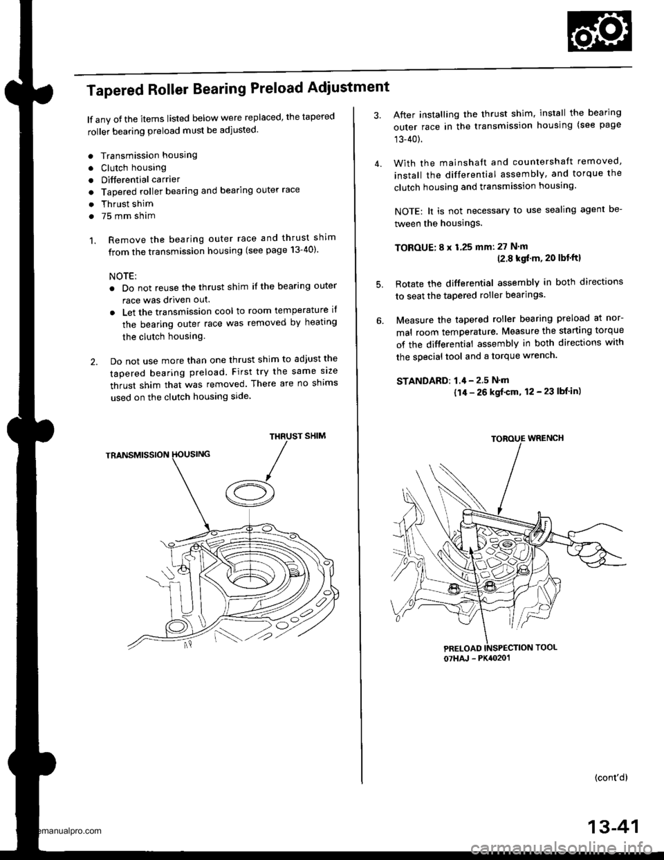
Tapered Roller Bearing Preload Adiustment
lf any oJ the items listed below were replaced, the tapered
roller bearing preload must be adjusted.
. Transmission housing
. Clutch housing
. Differential carrier
o Tapered roller bearing and bearing outer race
. Thrust shim
. 75 mm sham
1. Remove the bearing outer race and thrust shim
from the transmission housing (see page 13-40)'
NOTE:
. Do not reuse the thrust shim if the bearing outer
race was driven out.
. Let the transmission cool to room temperature il
the bearing outer race was removed by heating
the clutch housing.
2. Do not use more than one thrust shim to adjust the
tapered bearing preload. First try the same size
thrust shim that was removed. There are no shims
used on the clutch housing side
SHIMTHRUST
/A
After installing the thrust shim, install the bearing
outer race in the transmission housing (see page
13-40).
With the mainshaft and countershaft removed,
install the differential assembly, and torque the
clutch housing and transmission housing.
NOTE: lt is not necessary to use sealing agent be-
tween the housings.
TOBOUE; 8 x 1.25 mm: 27 N'm(2.8 kgf'm, 20 lbt'ftl
Rotate the differential assembly in both directions
to seat the tapered roller bearings.
Measure the tapered roller bearing preload at nor-
mal room temperature. Measure the starting torque
of the differential assembly in both directions with
the special tool and a torque wrench.
STANDAFD: 1.4 - 2.5 N'm
{1/r - 26 kgf'cm, 12 - 23 lbf in)
(cont'd)
4.
5.
07HAJ - PK4020'�1
13-41
www.emanualpro.com
Page 498 of 1395

30. Hold the transfer shaft with a 14 mm Allen wrench
clamDed in a bench vise.
NOTE: The locknut has left-hand threads.
TOROUE: 118 N.m (12.0 kgt'm,86.8 lbf'ft)
31. Stake the locknut on the transfer shaft using a 3.5
mm Dunch.
PUNCH3.0 - 3.5 mm{0.12 - 0.14 inl
14 mm ALLEN WRENCH
Totsl Starting Torquo Inspoction and Adiustment
32. Temoorarilv install transfer cover A without the O-
ring.
TRANSFER HOUSING
TRANSFER COVER A
oEl
€lE/Ehvc/E\\g8 x 1 .25 mm24 N.m (2.4 kg{ m, 17 lbtftl
5t.Secure the transfer housing in a bench vise with
soft jaws. then rotate the companion flange several
times to fit the tapered roller bearing,
TOROUE WR€NCH
34. Measure the total starting torque.
TOTAL STARNNG TOROUE:
1.70 - 2.08 N.m 117.3 - 21.2 kgf.cm, 15.0 - 18.i1 lbf inl
+ Transter Driven Gear Shaft Starting Torque Value
(wrot€ down in step 27).
(cont'd)
13-59
www.emanualpro.com
Page 517 of 1395

Automatic Transmission
Special Tools . 14'2OescriptionGeneral Operation . .... 14 3Power Flow . . .. '14_6
Electronic Control System .. .. . . .. .14_15Hydraulic Control .. 14 24Hydraulic Flow....-....... .. . .... .. .. . 14_29Lock'up Syslem .. .'t4'39Electrical SystemComponenl Locdlrons 14 45
PCM Circuil Dragram (A/T Control Svstem)'97 Model ....................... . . .. - . ... .14-46'98Model ................. . ... .. .. .1450'99 00Models.... . .... . . . 1452
PCM Terminal Voltage/Measuring ConditionsA"/T Control System-'97Model ...... ..14'48A,/T Control System -'98 00 Models . . .. . . 14 54
Troubleshooting Procedures .. ..... ... - 14_56Svmotom to comoonent CharlEiectr,cal Syslem -'97 Model . . 14 60Electrical System -'98 - OO Models . .. . . 14_62Electrical Troubleshooting ('97 Model)Troubleshooting Flowaharts .... ..... . .. . . 14_64
Electrical Troubleshooting ('98 - 00 Models)Troubleshootinq Flowclt"n" .... . ....- . .14-93ElectricalTroublesliooting('99 00Models)Troubleshootino FlowchartO/D OFF Indicator Light Does Not Come On 14 131
O/D OFF Indicator Liaht On ConstantlY . . . .1!-132O/D OFF Indicator Light Does Not Come OnEven Though O/D Switch ls Pressed . .... - 14_133
Lock up Control Solenoid Valve A,/B AssemblyTest....................-......... . .14-135Replacement . .ll_135Shifr ControlSolenoid Valve Ay'B Assembl,Test .............................. . .. 14-136
Replacement..............- . .14'136Linear Solenoid AssemblYTest.............................................. .. .... . 14_137Replacement .. . 14138Marnshaftlcountershafl Speed SensorsReplacement ...-... 14_138A/T Gear Position SwitchTest ..........................-... . .. 14-139ReplacementA/T Gear Positionlndicator.................. 14-140
Valve Eodynepair ............................... ..... . . .. - . .. ... 14 192
Assembly .................... .. 1{_193
Valve CapsDesciiption....-........................ .. ...... 14194
tnspeition ................... .. 14' 195
N4ain Valve BodyDisassembly/lnspection/Reassemblv - ...... .. 14_196
Secondarv Valve BodYDisassemblv4nspectron/ReassemblY .. . 14 198
Reoulator Valve Bodvbisassembtv,lnspiction/Reassemblv . 14199
Servo EodvDisassembly/lnspection/Reassembly ... ....14'200
Lock'uo Valve BodYDis;ssembly/lnspection/Reassembly .... . 14_201
MainshaftDisassembly/lnspection/Reassembly .. .. .. ..14'202
Inspection ....-.............. ..11_203
Sealing RingsReilaceient ...... ..... . 14'204
CountershaftDisassembly/lnspection/Reassembly .. . . . . . 11-205
Disassembly/Reassemb|y . . ........ ...... . .. 14_206Inspedron ................ . .... . 14 207
One wav ClutchDisassembly/lnspection/ReassemblY ... 11_209
Sub-shaftDisassembly/lnspection/Reassembly ... . .. . 14-210
oisassembly/Re6ssembly . . ... .-...... . . ..14-211
Sub-shaft BearingsReplacement .......14'212
Clutchllfustrated Index .......... . . .14-213
Disassembly .... .. .....14-216Reassembfy .... . .. .. . 14'218
Differentialllfustrated Index " 14-222Backlash Inspection . .... . .14'223
Bearing Repiacement .. 11-223
Differe-ntial Carrier Replacement .. .. . . . .. ..11-2?4
OifSeal Replacement. . .. 14'225
Side Clearance lnspection . . - .. ... . - ...... . .. 11'226
Transmission Housing BearingsMainshaJVCountershaft EearingsRepfacement .......14221Sub'siralt Eearing Replacement . . . . . . . . . ..11'224
Toroue Converter Housing BearingsMainshattEearing/OilSe6lReplacement . .. l4229
Countershaft Bea;ing Replacement.. .... .. ..14-230
Input Test - '97 - 98 ModelsInput Test '99 - 00 Models
Symptom to-Component ChartHydraulic System ...............
Checking
Removal ...,lllustrated Index (4WD)
Interlock SystemInterlock ControlUnit lnputTest. -..... -.. .... . - 14 144* Key Interlock Solenoid Test .- .. . . . - . . . ..... 14_146* Shift Lock Solenoid Test ..............-.-. . .. . ... .... 14 147*Shift LockSolenoidReplacement...... .. . .. .. 14 148* park pin Switch Test ......... 14 119' Park Pin Switch Replacement- '97 - 98 Models ....... 14-150* Park Pin Swirch/Over Drive (O/Di SwitchReplacemenl '99-00Models . .. 14_151over-Drive (O/D) Switch {'99 00 [4odels]Test........_..................... .......14-152Hydr.ulic System
..............._............... t4 142.................................. 14-143
Control Lever AssemblyR6placement ......,.,Reverse ldler Gear
lllustrated lndex
.......... 14-230
14 231
11-231
1nsta1|ation ..................Park StopInspeclion/AdjustmenlTransfer AssemblY.......14.232
RoadTest.............-.... ........ .StallSpeedTest ....._........................ ....... 14-159Fluid Level......_................... 14'160
Disessembly .................... 14-235Transfer Drive Gear BearingReplacementTrans{er Driven Gesf Shaft BearingReplacementTransfer Housing Roller BearingReplacementTransfer Cov€r A Bearing Outer RaceReplacementTransfer Housing Bearing Outer RaceReplacement ......-..,,,,,.....ReassemblvTransmassaonBeassembly ... -.. .... .14 250
Torque Converier/Drive Plate . .-. .... .. . ... .....14_258
Transmissionlnstatlation .................. ....... 14'259
Cooler Flushing . . ......11-261ATF Cooler HosesConnection.................. ....... 14-266I Shift LeverRemoval/lnstallation . .. 14'261
Disassemblv/Reassemblv - '97 - 98 Models . . 14_264
Disassembli/Reassemblv -'99 - 00 Models . 14-269
Over'Orive (O/D) Switch WireClearanceAdjustment. - ... . . . .. .. . 14'270
Detent Spring Replscement . . -.. ... .14'271*Shift CableAdiustment ....... 14'272
Repfacement.............. . 11'273
14 15711-237
11-237
14-238
$-234
11-23914-240
Transmigrion
Inspeclron ....., ...........Transfer AssemblyRemova1,.,,,..............,lnstallalion ........... .. ...Transmission
14 164
14-16514,167
14-169
End Cover/Transmissio . 14'174Transmission Housing .... ... .. . . .... .. 14-176Torque Converter Housingly'alve Body.. - ... -. 14 178
lllustrated lndex (2WD)End Cover/Transmissio ....... 14 180Transmission Housing . . ... . .. .... ... 14'182Torque Convener Housing/r'alve Body ......- 14-184
End CovefRemovat ...................... ....... 14'186Transmission HousingRemoval ...................... .. 14_188Torque Convener HousingA/alve BodYRemovat ................-..... .-..... 14-190
www.emanualpro.com
Page 763 of 1395

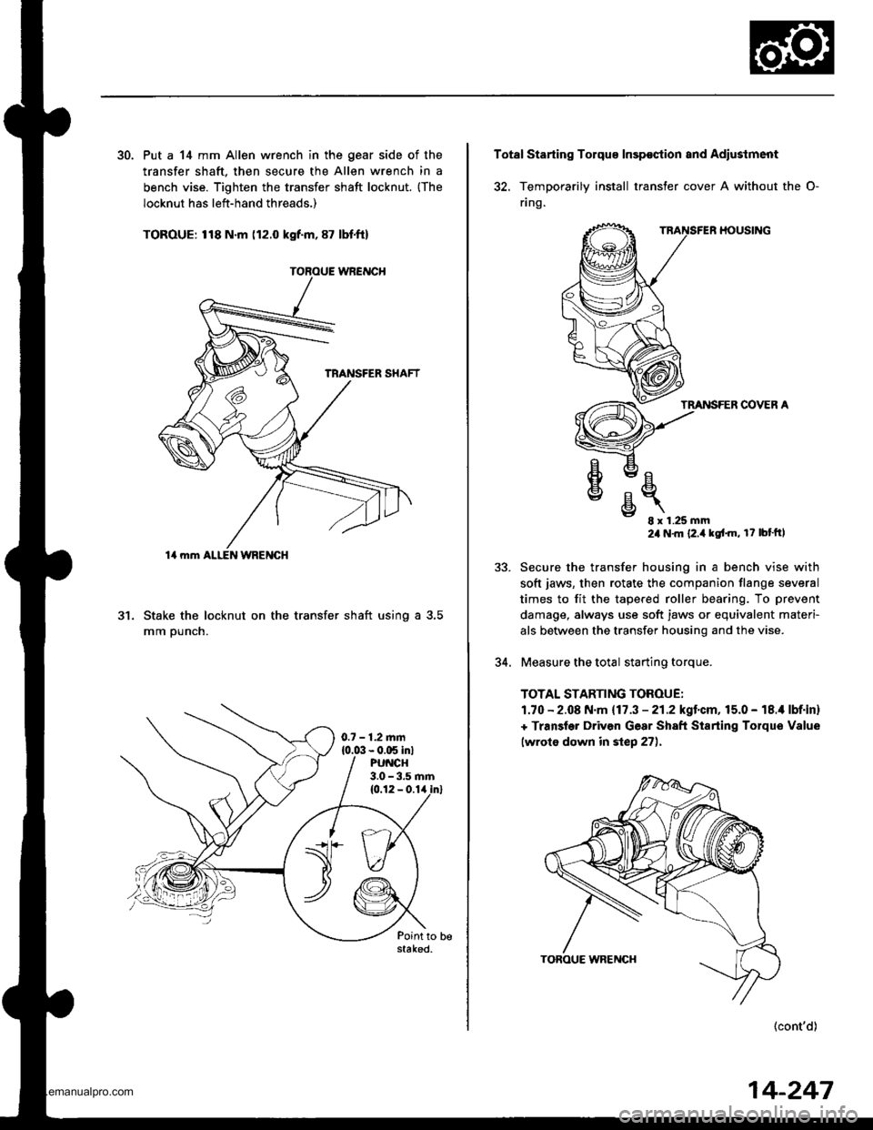
30. Put a 14 mm Allen wrench in the gear side of the
transfer shaft. then secure the Allen wrench in a
bench vise. Tighten the transfer shaft locknut. {The
locknut has left-hand threads,)
TOROUE: 118 N.m (12.0 kgf.m, 87 lbt.ft)
Stake the locknut on the transfer shaft using a 3.5
mm ounch.
al
14 mm ALI-EN WRENGH
0.7 - 1.2.nm{0.0:1- 0.C5 in}PU CH3.0 - 3.5 rnm
Total Starting Tolqu€ Insp€ction and Adiustment
32. TemDorarilv install transter cover A without the O-
flng.
HOUSING
TMNSFER COVER A
e
€
v
E- 8x1.25mm24 N'm {2.i1kgt'm, r? bt'ftl
Secure the transfer housing in a bench vise with
soft jaws, then rotate the companion flange several
times to fit the tapered roller bearing. To prevent
damage, always use soft jaws or equivalent materi-
als betlveen the transfer housing and the vise.
Measure the total starting torque.
TOTAL STARTING TOROUE:
1.70 - 2.08 N.m {17.3 - 21.2kgl.cm,15.0 - 18.i1 lbf.in}
+ Transler Driven Gear Sh8ft Starting Torque Value
lwroto down in step 27).
(cont'd)
5J.
34.
14-247
www.emanualpro.com
Page 840 of 1395

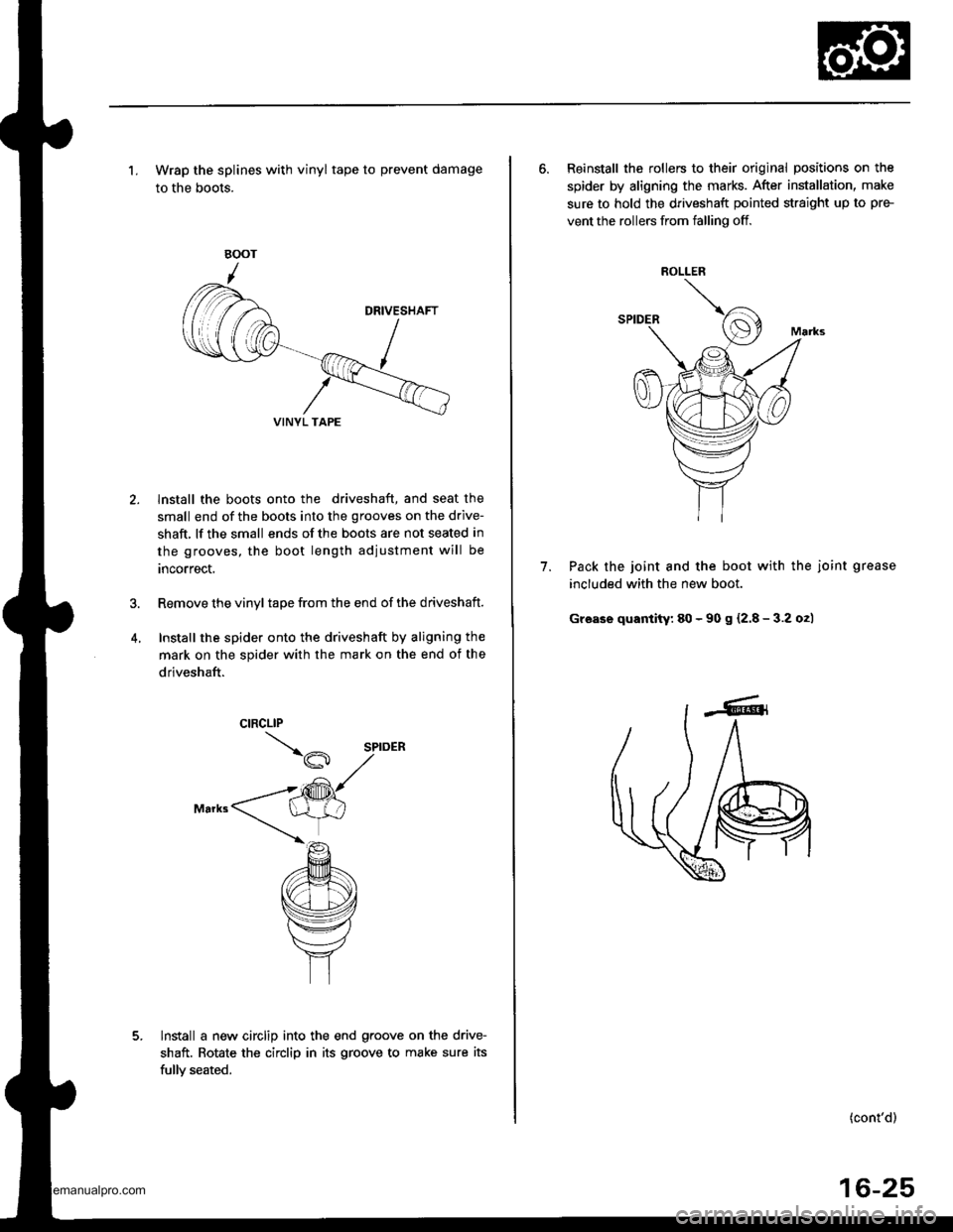
'1. Wrap the splines with vinyl tape to prevent damage
to the boots.
lnstall the boots onto the driveshaft, and seat the
small end of the boots into the grooves on the drive-
shaft, lf the small ends of the boots are not seated in
the grooves, the boot length adiustment will be
rncorrect.
Remove the vinyl tape from the end of the driveshaft.
Install the spider onto the driveshaft by aligning the
mark on the spider with the mark on the end of the
driveshaft.
lnstall a new circlip into the end g.oove on the drive-
shaft. Rotate the circlip in its groove to make sure its
fullv seated.
VINYL TAPE
6. Reinstall the rollers to their original positions on the
spider by aligning the marks. After installation, make
sure to hold the driveshaft pointed straight up to pre-
vent the rollers from falling off.
Pack the joint and the boot with the joint grease
included with the new boot.
Grease quantity: 80 - 90 s {2.8 - 3.2 o2)
7.
ROLLER
(cont'd)
16-25
www.emanualpro.com
Page 846 of 1395

Steering
Special Toofs ............. 17-2
Component Locations
Index ................ ....... 17-3
Troubleshooting
General Troubleshooting ................ 1 7-4
Noise and Vibration ......................... 17-8
Fluid Leaks ............. 17-10
Inspection and Adiustment
Steering Operation .......................... 17-12
Power Assist Check
With Vehicle Parked ....................
Steering Linkage and Gearbox .......
Pump Belt
Rack Guide Adjustment ...................
Fluid Rep|acement ...................,,.,....
Pump Pressure Check .................,,...
*Steering Wheel
Removal ................. 17-18
*Steering Column
Removal/lnstallation ................ ....... 17 -2O
lnspection .............. 17-21
Steering Lock Replacement ............ 17 -22
Power Steering Hoses, Lines
Ffuid Leakage Inspection ................. 17 -23
Repfacement .......... 17-23
Power Steering Pump
Repfacement .......... 17-24
Disassembly ...........17-25
fnspection .............. 17-26
Reassembly ............ 17-28
Power Steering Gearbox
Removal ................. 17-31
Disassembly ........... 17-34
Reassembly ............ 17-40
Ball Joint Boot Replacement .......... 17-50
Installation ............. 17-51
17-12
17-13
17-14
l7-15
17-15
17-16
Disassembly/Reassembly............... 17-18
4'%/b.......... -r'-7--a/
SUPPLEN\EN AL RES\RA(N SYSTES{ (SRS\
This model has an SRS which includes a driver's airbag in the steering wheel hub. a passenger's airbag in the dashboardabove the glove box ('97 - 00 models), and seat belt tensioners in the seat belt retractors ('98 - 00 models). Informationnecessary to safely service the SRS is included in this Service Manual. ltems marked with an asterisk (*) on the contentspage include, or are located near, SBS components. Servicing. disassembling or replacing these items will require specialprecautions and tools, and should only be done by an authorized Honda oearer.
To avoid rendering the SRS inoperative, which could lead to peFonal iniury or death in the event of a sevore trontalcollision. allSRS service work must be performod by an authorized Honda dealer.lmproper service procedurgs, including incorrect removal and installalion of the SRS, could lead to personal iniurycaused by unintontional deployment of th€ airbags {'97 - 00 models), and seat belt tensioners ('98 - 00 modelsl.Do not bump the SRS unit. Otherwise, the system may lail in case ot a collision, or the airbags may deploy when theignition switch is ON (lll.
SRS electrical wiring harnesses are identitied by yellow colof coding. Ralated components are located in the steeringcolumn, front console, dashboard, dashboard lower panel, and in the dashboard above the glove box. Do not use elec-trical test equipment on these cilcuits,
www.emanualpro.com