Page 859 of 1395
Inspection and Adjustment
Pump Belt
When using a new belt. first adjust the deflection or ten-
sion to the values for the new belt, then readjust the
deflection or tension to the values for the used belt after
running engine for five minutes.
Inspection
Note these items during inspection:
a lf there are cracks or any damage evident on the belt,
replace it with a new one.
. Follow the manufacturer's instructions lor the tension
gauge.
'1. Remove the P/S reservoir from the bracket, and set
it aside.
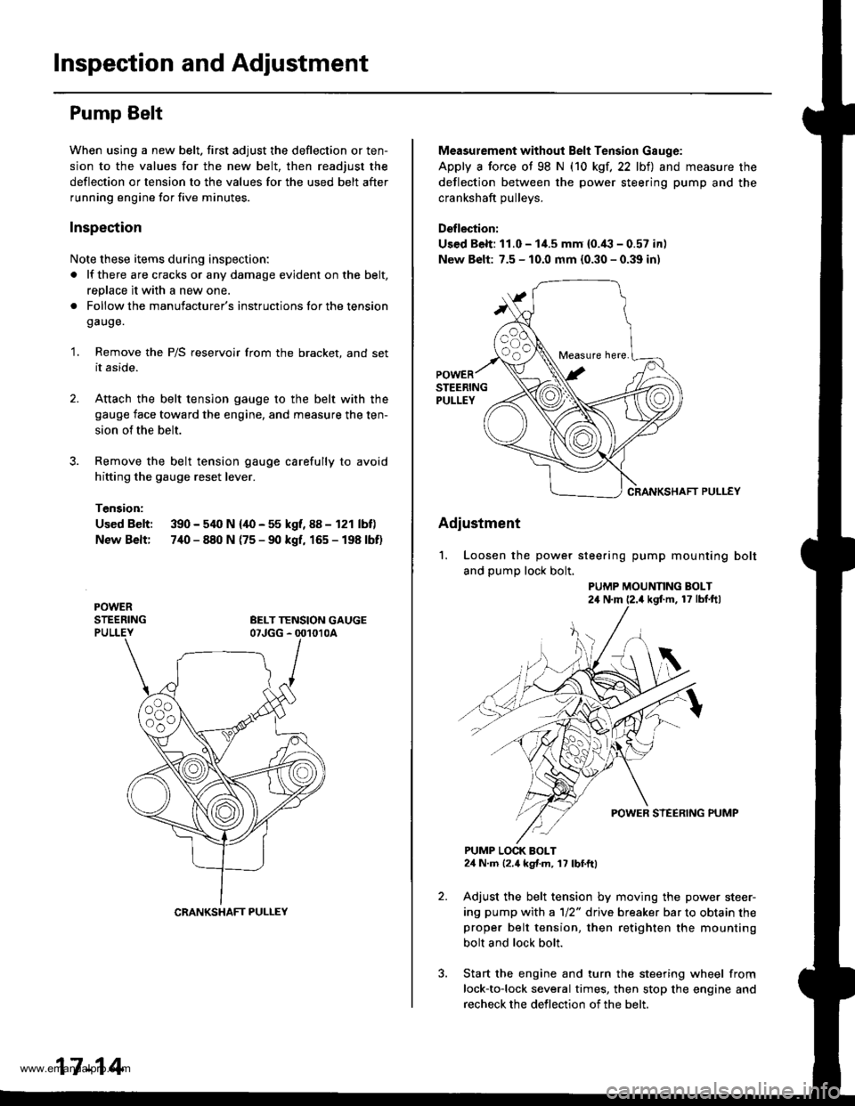
2. Attach the belt tension gauge to the belt with the
gauge face toward the engine, and measure the ten-
sion of the belt.
Remove the belt tension gauge carefully to avoid
hitting the gauge reset lever.
Tension:
Used Belt: 390 - 540 N {40 - 55 kgf, 88 - 121 lbf)
New Belt: 7,[0 - 840 N (75 - 90 kgf, 165 - 198 lbf)
CRANKSHAFT PULLEY
17-14
Measurement without Belt Tension Gauge:
Apply a force ot 98 N (10 kgf,22 lbt) and measure the
deflection between the power steering pump and the
crankshaft oullevs.
Deflection:
Used Belt: 11.0 - 1i1.5 mm {0.'(l - 0.57 in)
New Belt: 7.5 - 10.0 mm {0.30 - 0.39 in)
CRANKSHAFT PULLEY
Adiustment
'1. Loosen the power steering pump mounting bolt
and pump lock bolt.
PUMP MOUNNNG BOLT24 N'm (2.4 kgf'm, 17 lbf ftl
PUMP LOCK BOLT24 N.m 12.4 kgf.m, 17 lbf.ftl
Adjust the belt tension by moving the power steer-
ing pump with a 1/2" drive breaker bar to obtain theproper belt tension, then retighten the mounting
bolt and lock bolt.
Start the engine and turn the steering wheel from
lock-to-lock several times, then stop the engine and
recheck the deflection of the belt.
Measure here.
www.emanualpro.com
Page 899 of 1395
Suspension
Special Tools ............. 18-2
Component Locations
lndex ................ ...... 18-3
Wheel Alignment
Service lnformation ......................,.. 18-4
Camber .................. 18-4
Caster ............... ...... 18-5
Front Toe Inspection/
Adiustment ........ 18-5
Rear Toe Inspection/
Adiustment ........ 18-6
Turning Angle Inspection/
Adiustment ........ 18-6
Wheel/Hub Inspection
Bearing End Play .......................,...... 18-7
Wheel Runout ....... 18-7
Front Suspension
Suspension Arms Replacement ..... 18-8
Knuckle/Hub Replacement ............. 18-9
Lower Ball Joint Replacement ....... 18-15
Ball Joint Boot Replacement .......... 18-16
Front Damper
Removal ................. 18-16
Disassembly/lnspection .................. 18-1 7
Reassembly ........... 18-18
lnstallation ............. 18-18
Rear Suspension
Suspension Arms Replacement ..... 18-19
Hub Bearing Unit Replacement ...... 18-20
Upper Arm Bushing
Replacement ..... 18-23
Rear Damper
Removal ................. 18-23
Disassembly/1nspection .................. 18-24
Reassembly ........... 18-25
lnstallation ............. 18-25
www.emanualpro.com
Page 903 of 1395
Front Toe Inspection/Adjustment
Use commercially-available computerized four wheel
alignment equipment to measure wheel alignment (caster,
camber, toe, and turning angle). Follow the equipment
manufacturer's instructions,
3.
1.Check the tire pressure.
Center the steering wheel spokes.
Check the toe with the wheels pointed straight
ahead.
Front toe-in: 0 i 3 mm {0 t 1/8 inl
- lf adjustment is required, go on to step 4.
- lf no adjustment is required, remove alignment
equipment.
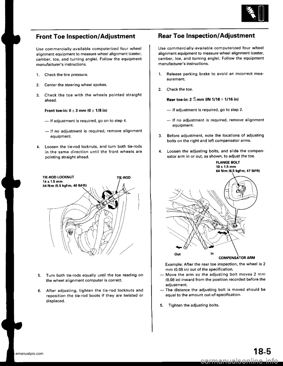
Loosen the tie-rod locknuts, and turn both tie-rods
in the same direction until the front wheels are
pointing straight ahead.
5.Turn both tie-rods equally until the toe reading on
the wheel alignment computer is correct.
After adjusting, tighten the tie-rod locknuts and
reposition the tie-rod boots if they are twisted or
displaced.
sir N m (5.5 kgJ.m, 'O lbf.ft)
Rear Toe Inspection/Adjustment
Use commercially-available computerized four wheel
alignment equipment to measure wheel alignment (caster,
camber. toe, and turning angle). Follow the equipment
manufacturer's instructions.
Release parking brake to avoid an incorrect mea-
surement.
Check the toe.
Ro8r toe-in: 2 :1 mm {lN l/16:t 1/16 in,
- lf adjustment is required, go to step 2.
- lf no adiustment is required. remove alignment
equrpmenr.
Before adjustment, note the locations of adjusting
bolts on the right and left compensator arms.
Loosen the adjusting bolts, and slide the compen-
sator arm in or out. as shown, to adiust the toe.
1.
FLANGE BOLT'10 x 1.5 mm
COMPENSATOR ARM
Example: After the rear toe inspection, the wheel is 2
mm (0.08 in) out of the specification.- Move the arm so the adjusting bolt moves 2 mm
{0.08 in) inward from the position recorded before the
adjustment.- The distance the adjusting bolt is moved should be
equal to the amount out-of-specification.
5. Tighten the adjusting bolts.
6a N.m 16.5 kgf.m, 47 lbf'ftl
18-5
www.emanualpro.com
Page 925 of 1395
Brakes
Special Tools ............. 19-2
Component Locations
lndex ................ ...... 19-3
Inspection and Adlustment
Brake System Rubber Parts
and Brake Booster ..........,,,.......... 19-4
Brake Pedal ............ 19-5
Parking Brake ........ 19-6
Bleeding ................. 19'7
Brake System Indicator ................... 19-8
Front Brake Pads
Inspection and Replacement .......... 19-9
Front Brake Disc
Disc Runout Inspection ................... 19-11
Disc Thickness and
Parallelism Inspection ........,........ 19-1 1
Front Brake Caliper
Disassembly/Reassembly ............... 19-12
Master Cylinder/Brake Booster
Removal/lnstallation ....................... 19-13
Master Cylinder
Inspection/Disassembly .............. 19-14
Pushrod Clearance Adiustment ...... 19-14
Brake Booster Inspection ...,.,,,,....... 1 9-1 5
Rear Drum Brakes
Inspection .............. 19-15
Brake Shoes
Replacement ..... 19-r 8
Wheel Cylinder Replacement ......... 19-20
Brake Hoses/Lines
Inspection/Torque Specifications ... 19-21
Hose Replacement ....,...,............. ..,,, 19-22
Parking Brake Cable
Inspection and Replacement .......... 19-23
www.emanualpro.com
Page 926 of 1395
Special Tools
Ref. No. Tool Number Description ety psge Reference
(, | 07JAG. SD40100 | Pushrod Adiustment cauge I r I tg_rt
19-2
www.emanualpro.com
Page 929 of 1395
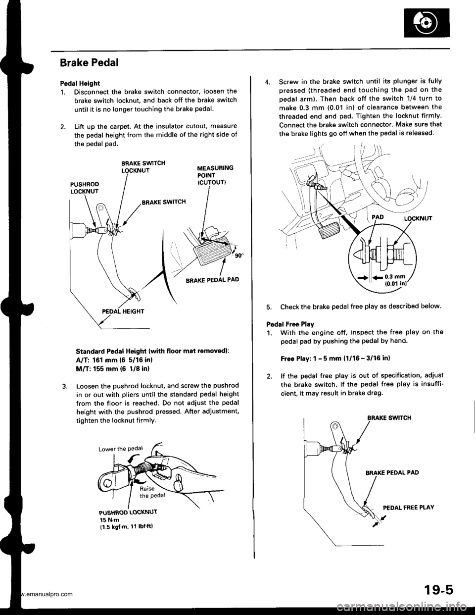
Brake Pedal
Pedal Hoight
1. Disconnect the brake switch connector, loosen the
brake switch locknut, and back off the brake switch
until it is no longer touching the brake pedal.
2. Lift up the carpet, At the insulator cutout, measure
the pedal height from the middle of the right side of
the oedal pad.
BRAKE SWITCH
ERAKE SWITCH
Standard Pedal Height (with floor m8i removed):
A/T: 161 mm (5 5/16 in)
M/T: 155 mm {6 U8 in}
Loosen the pushrod locknut, and screw the pushrod
in or out with pliers until the standard pedal height
from the floor is reached. Do not adjust the pedal
height with the pushrod pressed. After adiustment,
tighten the locknut firmly.
PUSHROD LOCKNUT
15 N.m11.5 kgj m, 11 lbf ftl
4. Screw in the brake switch until its plunger is fully
pressed (threaded end touching the pad on the
pedal arm), Then back otf the switch 1/4 turn to
make 0.3 mm (0.01 in) of clearance between the
threaded end and pad. Tighten the locknut firmly.
Connect the brake switch connecto.. Make sure that
the brake lights 90 off when the pedal is released
5. Checkthe brake pedalfree play as described below
Pedal Free Play
1. With the engine off. inspect the free play on the
pedal pad by pushing the pedal by hand-
Free Play: 1 - 5 mm (1/16 - 3/16 in)
2. lf the pedal free play is out of specification, adiust
the brake switch. lf the pedal free play is insuffi-
cient, it may result in brake drag.
swtTcH
PEOAL PAD
PEDAL FREE PLAY
19-5
www.emanualpro.com
Page 930 of 1395
Inspection and Adjustment
Parking Brake
Inspeqtion
1. Pull the parking brake lever with
lbfl force to fully apply the parking
The parking brake lever should be
specified number of clicks.
L.var Lockod Clicks: 2 - 6
196 N (20 kqf, 44
brake.
locked within the
2. Adjust the parking brake if the lever clicks are out ofspecification.
Adiustment
1. Raise the rear wheels off the ground. and support
the vehicle on safety stands.
@@ Bbck tho front who€ts betore iackingup the rear ot tho vohicle.
2. Remove the parking brake cover
PARKING BRAKE COVER
19-6
3. Release the parking brake lever.
Adjust the parking brake by turning the adjusting
nut.
Check that the parking brakes do not drag when therear wheels are turned. Readjust if necessary.
Make sure the parking brakes are fully applied when
the parking brake lever is pulled up fully.
Installthe parking brake cover.7.
www.emanualpro.com
Page 982 of 1395
Body
Bumpers
Front Bumper Removal and
fnstaflation .........20-72
Rear Bumper Removal and
fnstaflation .........20-74
'Dashboard
lnstrument Panel Removal and
lnstallation .........20-47
Driver's Dashboard Lower Cover and
Knee Bolster Removal and
Installation .........20-48
Glove Box Removal and
lnstallation .........20-49
Center Pocket Removal and
lnstallation .........20-49
Center Dashboard Lower Cover
Removal and lnstallation ............ 20-50
Center Panel Removal and
lnstallation .........20-50
Power Window Switch Removal and
lnstallation .........20-51
Center Air Vent Removal and
lnstallation .........20-51
Side Air Vent Removal and
fnstallation .........20-52
Side Defogger Trim Removal and
fnstallation .........20-52
Dashboard Removal and
lnstallation .........20-53
Dashboard Frame Replacement ..... 20-55
Doors
Component Location Index
Front Door ,,...,,,,20-2
Rear Door ...........20-4
Tailgate Door ................................ 20-6
Fenderwell
Front Wheelwell Protector
Replacement .....20-89
Inner Fender Replacement .,.....,.,.... 20-89
Rear Wheelwell Protectol
Replacement .....20-90
Fuel Pipe Protector Replacement ... 20-90
Rear Air Outlet Replacement .......... 20-91
*Frame Repair Chart .............................. 20-106
Front Grille
Repf acement .........20-77
Glass
Component Location Index ............ 20-29
Hood
Replacement ......,,,20-75
Adjustment ............20-76
*lnterior Trim
Component Location Index ............ 20-40
Mirrors
Component Location Index .........,,, 20-26
Moldings
Roof Molding Replacement ............ 20-84
Door Moldings Replacement .......... 20-85
Openers
Component Location Index ............ 20-92
Rear Hatch Glass
Replacement .........20-74
Disassembly and Reassembly ........ 20-79
Adiustment ............20-81
Rear Weatherstrip Replacement .... 20-83
Seats
Component Location Index ............ 20-56
Side Sill Panel
Repfacement .........20-87
Spare Tire Cover
Emblem Installation ........................ 20-88
Sub-frame ..................20-104
Wiper/Washer
Component Location lndex ,,,,,....... 20-97
www.emanualpro.com