1999 HONDA CIVIC 70-
[x] Cancel search: 70-Page 616 of 2189

Mainshaft Thrust Shim
Adjustment
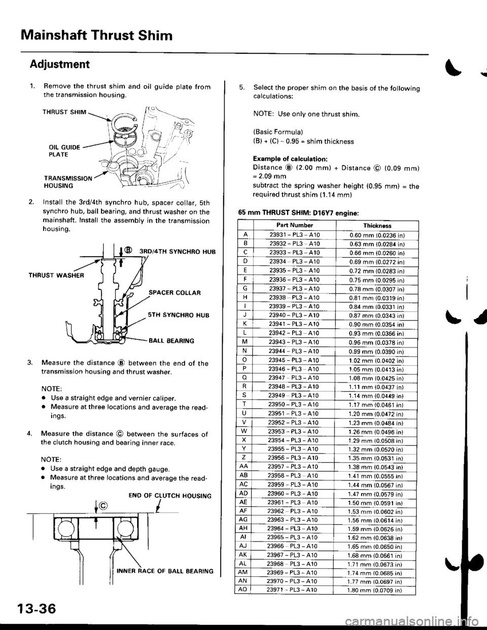
Remove the thrust shim and oil
the transmission housing.
1.gu ide plate from
THRUST SHIM
OIL GUIDEPLATE
TBANSMISSIONHOUSING
Install the 3rd/4th synchro hub, spacer collar, 5th
synchro hub, ball bearing, and thrust washer on themainshaft. Install the assembly in the transmission
h ousing.
@ gnol+lx syNcHRo HUB
THRUST WASHER
SPACER COLLAR
4.
Measure the distance @ between the end of thetransmission housing and thrust washer.
NOTE:
. Use a straight edge and vernier caliper.. Measure at three locations and average the read-
Ings.
Measure the distance @ between the surfaces ofthe clutch housing and bearing inner race.
NOTE:
. Use a straight edge and depth gauge.
. Measure at three locations and average the read-
Ings.
sTH SYNCHRO IIUB
BALL EEARING
CLUTCH
L
HOUSINGENO OF
13-36
INNER RACE OF BALL AEARING
\
5.Select the proper shim on the basis of the followingcalculations:
NOTE: Use only one thrust shim.
(Basic Formula)(B) + {C). 0.95 = shim thickness
Example of calculation:
Distance @ (2.00 mm) + Distance @= 2.09 mm
subtract the spring washer height (0.95
required thrust shim (1.14 mm)
65 mm THRUST SHIM: D16Y7 engine:
(0.09
mm)
mm)
= tne
r1
Part NumborThickness
23931 - PL3 A100.60 mm (0.0236 in)23932 - PL3 A100.63 mm 10.0284 in)c23933 - PL3 A100.66 mm {0.0260 iniD23934 PL3 - A100.69 mm (0.0272 in)
E23935-PL3-4100.72 mm 10.0283 in)
F23936-PL3-4100.75 mm 10.0295 in)G23937-PL3-A100.78 mm {0.0307 in}
23938 PL3 - A100.81 mm (0.0319 in)I23939 - PL3 At00.84 mm (0.0331 in)J23940-PL3-Ar00.87 mm (0.0343 in)
23941 - PL3 - A100.90 mm (0.0354 in)
L23942 - PL3 A100.93 mm (0.0366 in)
23943-PL3-A100.96 mm (0.0378 in)N23944 PL3 - A100.99 mm 10.0390 in)
o23945-PL3-A101.02 mm {0.0402 in}23946 - PL3 A101.05 mm (0.0413 in)o23947 PL3 - 4101.08 mm (0.0425 in)R23948-PL3-A101.11mm (0.0437 in)s23949 PL3 - A101.14 mm {0.0449 in}T23950-PL3-A101.17 mm (0.0461 in)
U23951 PL3 - A101.20 mm (0.0472 in)
23952-PL3-Ar01.23 mm {0.0484 in)
23953-PL3-A101.26 mm {0.0496 in}X23954 - P13, A101.29 mm (0.0508 in)23955 - PL3 A101.32 mm (0.0520 in)z23956-PL3-Ar01.35 mm {0.0531 in)
23957-PL3-A101.38 mm (0.0543 in)
AB239s8 - PL3 A101.41 mm (0.0555 in)AC23959 PL3 - A101.44 mm (0.0567 in)
AD23960 - PL3 A101.47 mm (0.0579 in)23961 - PL3 4101.50 mm (0.0591 in)23962 PL3 - A101.53 mm (0.0602 in)AG23963-PL3-4101.56 mm (0.0614 in)AH23964 - PL3 A101.59 mm (0.0626 in)AI23965-PL3-A101.62 mm {0.0638 in)
23966 PL3 - A101.65 mm (0.0650 in)AK23967-PL3-A101.68 mm {0.0661 in)
23968 PL3 - A101.71 mm {0.0673 in)23969-PL3-A101.74 mm (0.06a5 iniAN23970- PL3 -A101.77 mm (0.0697 in)AO23971 - PL3 - A101.80 mm 10.0709 in)
Page 617 of 2189

70 mm THRUST SHIM: Dl6Y5, Dl6Y8 engin€s
Part NumberThickness
23931 - PL3 - 8000.60 mm 10.0236 in)
23932-PL3-8000.63 mm (0.0284 in)
c23933-PL3-8000.66 mm (0.0260 in)
D23334-PL3-8000.69 mm 10.0272 in)
E23935-PL3-8000.72 mm (0.0283 in)
F23936 - PL3 8000.75 mm (0.0295 in)
23937-PL3-B000.78 mm (0.0307 in)
23938-PL3-8000.81 mm (0.0319 inl
23939-PL3-8000.84 mm (0.0331 in)
23940-PL3-8000.87 mm {0.0343 in)
23941 - PL3 - 8000.90 mm (0.0354 in)
L23942-PL3-8000.93 mm (0.0366 in)
23943-PL3-8000.96 mm (0.0378 in)
N23944-PL3-8000.99 mm i0.0390 in)
o2394s-PL3-8001.02 mm (0.0102 in)
P23946-PL3-8001.05 mm {0.0413 in}
o23947-PL3-8001.08 mm (0.0{25 in)
23948 - PL3 800'1.1'1 mm (0.0437 4n)
23949-PL3-8001.14 mm (0.0449 inl
T23950-PL3-8001.17 mm (0.0461 in)
23951 - PL3 - 8001.20 mm (0.0472 in)
23952-PL3-8001.23 mm (0.0444 in)
239s3-PL3-8001.26 mm {0.0496 in)
X23954-PL3-8001.29 mm (0.0508 in)
2395s-PL3-8001.32 mm (0.0520 in)
z23956-PL3-8001.35 mm (0.0531 in)
23957-PL3-8001.38 mm (0.0543 in)
A823958-PL3-8001.41 mm (0.0555 in)
AC23959-PL3-8001.44 mm {0.0567 in)
AD23960-PL3-8001.47 mm (0.0579 in)
2396'�t-PL3-8001.50 mm (0.0591 in)
23962-PL3-8001.53 mm (0.0602 in)
AG23963-PL3-8001.56 mm (0.0614 in)
AH23964-PL3-8001.59 mm (0.0626 in)
23965-PL3-8001,62 mm (0.0638 in)
23966-PL3-8001.65 mm (0.0650 in)
AK23967-PL3-8001.68 mm (0.0661 in)
23968-PL3-8001.71 mm (0.0673 in)
23969-PL3-8001.74 mm (0.0685 in)
AN23970-PL3-8001.77 mm (0.0697 in)
AO23971- PL3 8001.80 mm (0.0709 inl
6. Installthe oil guide plate and selected thrust shim in
ths transmission housing
NOTE:
. Clean the thrust washer, spring washel and
thrust shim thoroughly belore installation.
. lnstall the thrust washer, spring washer and
thrust shim proPerlY.
THRUST SHIM
I
OIL GUIDEPLATE
TRANSMISSIONHOUSING
8.
o
10.
7, Install the thrust washer and spring washer in the
mainshaft.
lnstall the mainshaft in the clutch housing
Place the transmission housing over the mainshaft
and onto the clutch housing.
Tighten the clutch and transmission housings with
several 8 mm bolts.
NOTE: lt is not necessary to use sealing agent
between the housings'
8 x 1.25 mm
27 N'm t2.8 kgf.m. 20 lbf'ft)
Tap the mainshaft with a plastic hammer.
Check the thrust clearance in the manner doscribsd
below.
CAUnON: Mc.suromont 3hould bo mlde !t room
tomp9laturs.
a. Slide the mainshaft base and the collar over the
mainshaft.
CLUTCHHOUSING
11.
lz.
MAITISHAFT BASE07GAJ-PG20130COLLAF07GAJ -PG20120
{cont'd}
13-37
THRUST WASHER
SPRING WASI{ER
Page 669 of 2189

72 mm Thrust Shim
t
Part NumberThickness
23931 - P21 0000.60 mm {0.0236 in}
23932-P21 -0000.63 mm 10.0248 in)
c23933 P21 - 0000.66 mm (0.0260 in)
D23934 - P21 0000.69 mm (0.0272 in)
E2393s-P21-0000.72 mm (0.0283 in)
F23936-P21 -0000.75 mm (0.0295 in)
G23937 -P21-O000.78 mm (0.0307 in)
23938-P21 -0000.81 mm (0.0319 in)
23939-P21 -0000.84 mm (0.0331 in)
J23940-P21 -0000.87 mm (0.0343 in)
K23941 P21 - 0000.90 mm (0.0354 ini
L23942 - P21 0000.93 mm (0.0366 in)
23943-P21 -0000.96 mm 10.0378 in)
N23944 - P21 -0000.99 mm (0.0390 in)
o23945 - P21 0001.02 mm (0.0402 in)
P23946 - P21 0001.05 mm (0.0413 in)
o23947 - P2l 0001.08 mm (0.0425 in)
R23948-P21 -0001.'1 'l mm (0.0437 in)
S23949 - P21 0001.14 mm (0.0449 in)
T23950 - P21 0001.17 mm (0.0461 in)
23951 - P21 -0001.20 mm (0.0472 in)
23952 - P21 -0001.23 mm (0.0484 in)
23953-P21 -0001.26 mm (0.0496 in)
X23954-P21 -0001.29 mm (0.0508 in)
23955 - P21 -0001.32 mm (0.0520 in)
z23956-P21 -0001.35 mm (0.0531 in)
23957-P21 -0001.38 mm 10.0543 in)
AB23958 - P21 -0001.41 mm (0.0555 in)
AC23959 P21 - 0001.44 mm {0.0567 in)
23960 - P21 0001.47 mm (0.0579 in)
AE23961 - P21 -0001.50 mm {0.0591 in)
23962 P21 - 0001.53 mm {0.0602 in)
AG23963-P21 -0001.56 mm (0.0611in)
AH23964-P21 -0001.59 mm {0.0626 in)
23965-P21 -000'1.62 mm {0.0638 in)
23965-P21 - 0001.65 mm (0.0650 in)
AK23967-P21 -0001.68 mm {0.0661 in)
23968 - P21 -0001.71 mm 10.0673 in)
23969 P21 - 0001.74 mm {0.0685 in)
AN23970-P21 -0001.77 mm {0.0697 in)
AO23971 - P21 -0001.80 mm (0.0709 in)
7. lnstallthe thrust shim selected and oil guide plate in
the transmission housing.
72 mm THRUSTOIL GUIDE PLATE
TRANSMISSIONHOUSING
8. Install the spring washer and washer on the ball
beaflng.
NOTE:
. Clean the spring washer, washer and thrust shim
throughly before installation.
. Install the spring washer, washer and thrust
shim properlY.
-WASH€R-<]>-.-'
x -sPRtNG WASHER
-.-sK((9r'
lnstallthe mainshaft in the clutch housing.
Place the transmission housing over the mainshaft
and onto the clutch housing.
Tighten the clutch and transmission housings with
several 8 mm bolts.
NOTE: lt is not necessary to use sealing agent
between the housings.
8 x 1.25 mm
27 N.m (2.8 kgf.m. 20 lbf'ft)
Tap the mainshaft with a plastic hammer.
(cont'd)
9.
10.
'I l.
12.
13-89
Page 1004 of 2189

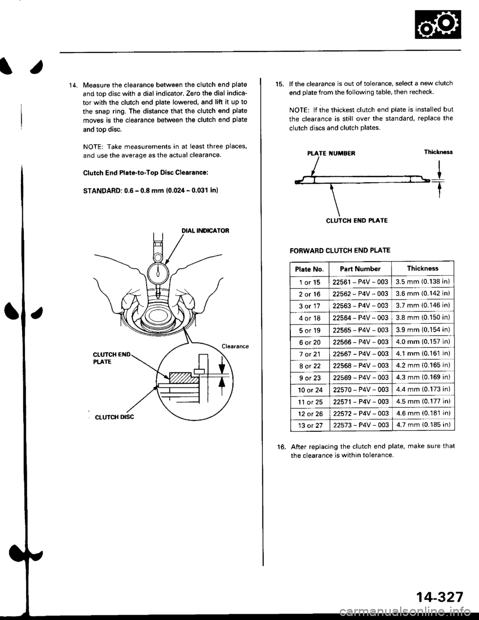
14. Measure the clearance between the clutch end plate
and toD disc with a dial indicator, Zero th€ dial indica-
tor with the clutch end plate lowered, and lift it up to
the snap ring. The distance that the clutch end plate
moves is the clearance between the clutch end plate
and toD disc.
NOTE: Take measurements in at least three places,
and use the average as the actual clearance.
Clutch End Plate-to-Top Disc Clesranc€:
STANDARD: 0.6 - 0.8 mm 10.024 - 0.031 inl
15. It the clearance is out of tolerance, select a new ciutch
end plate from the following table, then recheck.
NOIE: lf ihe thickest clutch end plate is installed but
the clearance is still over the standard, replace the
clutch discs and clutch Plates.
FORWARD CLUTCH END PLATE
After replacing the clutch end plate, make sure thal
the clearance is within tolerance.
16.
PTATE I{UMBEN
Plate No.Part NumberThickn€ss
1or1522561 - P4V - 0033.5 mm (0.138 in)
2or1622562 - P4V -OO33.6 mm (0.142 in)
3or1722563-P4V-0033.7 mm (0.146 in)
4or1822564 - P4V - 0033.8 mm (0.150 in)
5or192256s-P4V-0033.9 mm (0.154 in)
6ot2022566-P4V-0034.0 mm (0.157 in)
7 ot 2122567 -P4V -0034.1 mm (0.161 in)
8ot2222568-P4V-0034.2 mm (0.165 in)
9ot2322569-P4V-0034.3 mm {0.169 in)
10 or 2422570-P4V -OO34.4 mm (0.173 in)
'll or 2522571,P4V-0034.5 mm (0.177 in)
12 ot 2622572-P4V-OO34.6 mm (0.181 in)
13 ot 2722573-P4V -OO34.7 mm {0.185 in)
14-327
Page 1966 of 2189

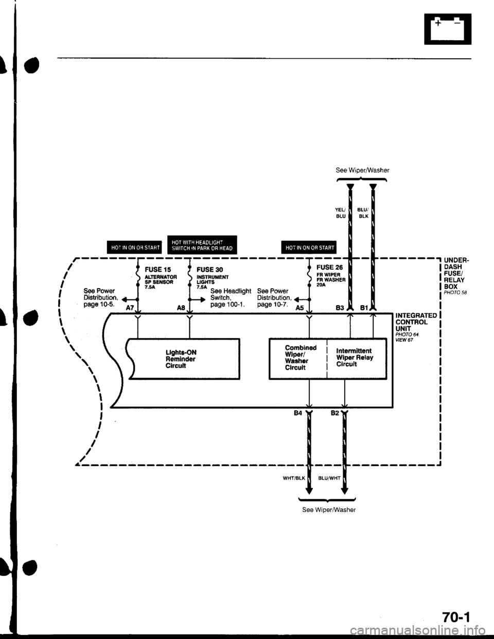
See Wiper,ryVasher
@
FUSE 30l|lslFl,|tEl{luotfT3
UNDER-DASHFUSE/RELAYBOX
I
t
I
I
I
.1 1
-t
\
\\
Sea PowerDistfibution,pag€ 10-5. iz
FUSE 15ALTEi}IATORsP 8S$80n?.54
A8
7'5A soe Headtight sss Power- Switch, Distibution,page 100-t. pags 1G7. foINTEGRATEDCONTNOLUNIT
vEw af
\
\
\
t
I
,
I
I
I
a-------
FUSE 26FR \I/IP€gFi WASTIEF204
Ught8.ONnemhderCircrti
lfllsnl|literWip6r RelayCircuit
Combin€dl,Ylper/WarhotCireuit
*I "'�r
II
II
-----[---t-----
""r,".* I ".u-"r l
tt\--
See WiperMasher
70-1