1999 HONDA CIVIC Fuel pressure
[x] Cancel search: Fuel pressurePage 550 of 2189

\
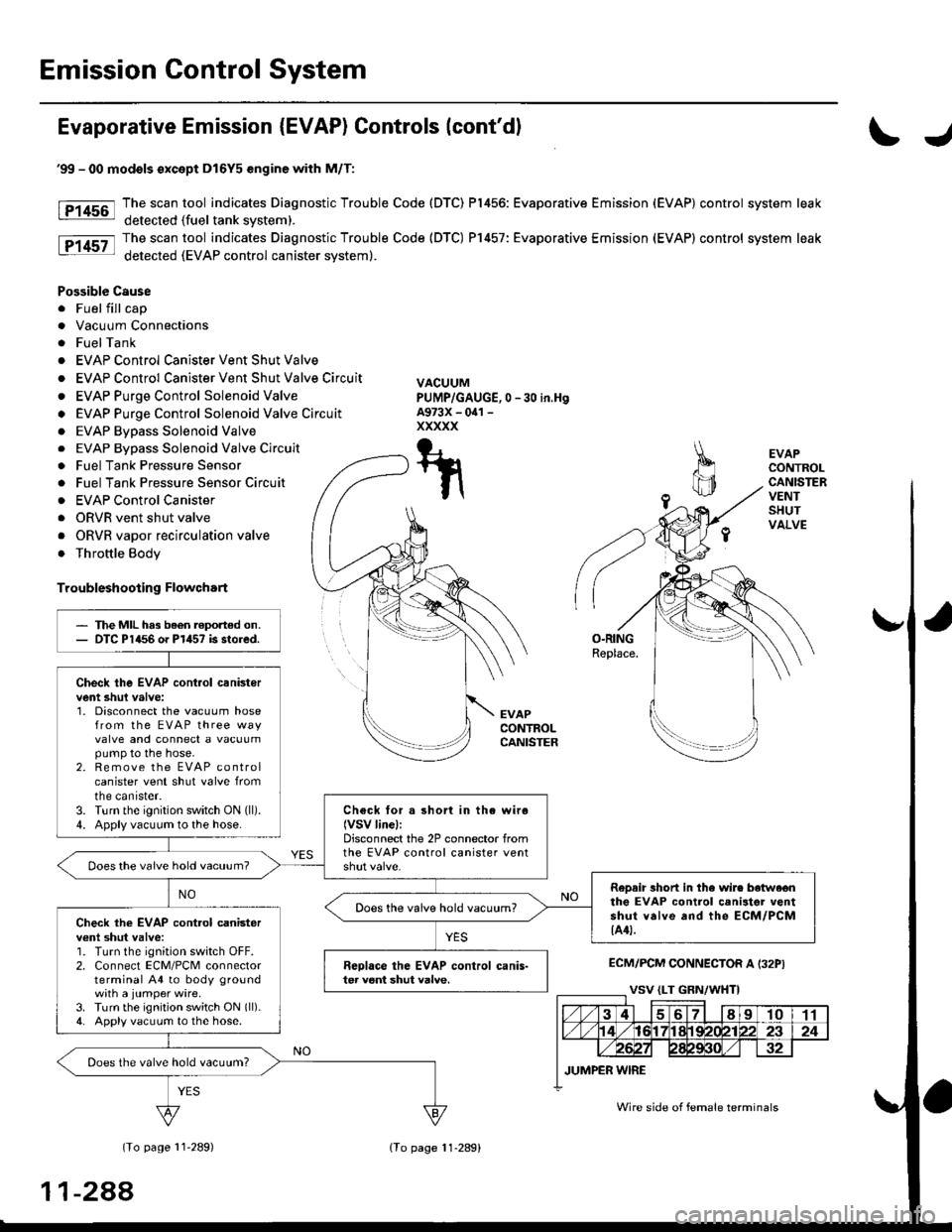
'99 - 0O modols except Dl5Y5 engine with M/T:
rFo45'::n":"tooIindicatesDiagnosticTroub|ecode(DTc)P0453:Ahighvo|tageprob|emintheFUelTankPressure
Wire side of temale terminals
FUEL TANKPRESSUNE SENSOR
SUB.HARNESS6P CONNECTOR {C574 (C568)}}
vcc2{YEL/BLUI
sG2IGRN/BLK)
Wire side of female terminals
PTANK{LT GRNI
(cont'd)
11-281
ECM/PCM CONNECTOR A {32P)
PTANK {LT GRN)
The MIL has been reported on.
DTC P0453 is stored.
Check the vacuum lines:
Check the vacuum lines ot the
fuel tank pressure sensor for mis-
routing, leakage, breakage and
clogging.
Are the vacuum lines OK?
Problem verilication:1. Do the ECM/PCM Reset Proce-
du re,2. Remove the fuel fill caP
3. Turn the ignition switch ON (ll).
4. Monitor the FTP Sensor volt'
age with the Honda PGM
Tester, or measure voltage
between body ground and
ECM/PCM connector terminalA.29.
lntermittent failuro. svstem b OK
at this time. Check for Poor con_
noctions or loo3€ wire3 at C131
{located under tight side of dash),
C4Ol {located above underdash
fuse/relay boxl, C57{ (C5681'
llocaled unde. access Panell,C792 {fuel tank Pressure sensorl
aod ECM/PCM.
ls there approx.2.5 V?
Ch€ck for an open in the wira
{SG2line):1. Turn the ignition switch OFF.
2. Reinstall the fuel fill caP
3. Remove the access Panellrom the floor.
4. Disconnect the fuel tank Pres-sure sensor sub-harness 6P
5. Turn the ignition switch ON (ll)
6, At the access Panelside, mea-
sure voltage between the fuel
tank pressure sensor sub_har-
ness 6P connector termlnals
No.5 and No.6.
Repair open in the wire between
the fueliank Pres3ure 3ensor and
ECM/PCM {Cl8).ls there approx.5 V?
Check lor an oPen in the wire
{PTANK linel:At the access Panel side, mea
sure voltage between the fuel
tank pressure sensor suo_harness
6P connector No. 2 terminal and
No. 6 terminal.
ls there approx. 5 V?
(To page 11.282)
Page 552 of 2189

\
t,96 D16Y8 engine (coup6l,'9? Dl6Y7 engine (coupe: KL model, sedan: KL (LX) model)"g7 Dl6Y8 ongine (coupe: all mod-
els, sedan: KL model,'98-8ll modelsl 39 - 00 Dl5Y5 engine with M/Tl:
The scan tool indicates Diagnostic Trouble code (DTc) P1456: Evaporative Emission (EVAP) control system leak
detected (fuel tank sYsteml
The scan tool indicates Diagnostic Trouble Code (DTC) P1457: Evaporative Emission (EVAP) control system leak
detected (EVAP control canister system).
Fr4t6l
fF14s7
Possible Causs
. Fuel fill cap
. Vacuum Connections
. Fuel Tank
. EVAP Control Canister Vent Shut Valve
. EVAP Control Canister Vent Shut Valve Circuit
. EVAP Purge Control Solenoid Valve
. EVAP Purge Control Solenoid Valve Circuit
. EVAP Bypass Solenoid Valve
. EVAP Bypass Solenoid Valve Circuit
. Fuel Tank Pressure Sensor
. Fuel Tank Pressure Sensor Circuit
. EVAP Control Canister
. Throttle Body
Troublsshooting Flowchart
VACUUMPUMP/GAUGE,0 - 30 in.HgA973X - 041 -
xxxxx
I
EVAPCONTROL
.4, cANrsrER
re ./ VALVE
{S----r*::n
\(cont'd)
- The MIL ha3 been rePofted
on.- DTC P1456 or P1457 is stored.
Check the EVAP control canbtol
vent shut valve:1. Disconnect the vacuum hose
Irom the EVAP three waY
valve and connect a vacuurnpump to the hose.
2. Remove the EVAP control
canister vent shut valve Irofi
the canrster.3. Turn the ignition switch ON (lli
4. Apply vacuum to the hose.
Chock for . shon in the wire(VSv linel:Disconnect the 2P connector {rom
the EVAP control canister vent
Does the valve hold vacuum?
Repair short in the wir€ betwcen
the EVAP control canister vent
shut v.lve and tho ECM/PCM
tA29|.
Does the valve hold vacuum?
Check the EVAP control canister
vent shui valve:1. Turn the ignition switch OFF.
2. Connect ECM/PCM connectorterminal A29 to body ground
with a iumPer wire.
3. Turn the ignition switch ON (ll).
4. Applyvacuum to the hose
Reohce the EVAP control canis-
ter vent shttt valve.
Does the valve hold vacuum?
ECM/PCM CONNECTOR A {32P)
37I9t01t't2t3t5t6ItItt9202a2a
25aA
ILT GRN/W{T) I JUMPER WIRE
Wire side of femll terminals
(To page 11-284i(To page 11 284)
11-283
Page 557 of 2189

Emission Control System
Evaporative Emission {EVAP) Controls (cont'dl
\J
tF1456-l
tP14sz-l
EVAPCONTROLCANISTERVENTSHUTVALVE
O.RINGReplace.
EVAPCONTROLCANISTER
ECM/PCM CONNECTOR A I32PI
(To page 11'289)
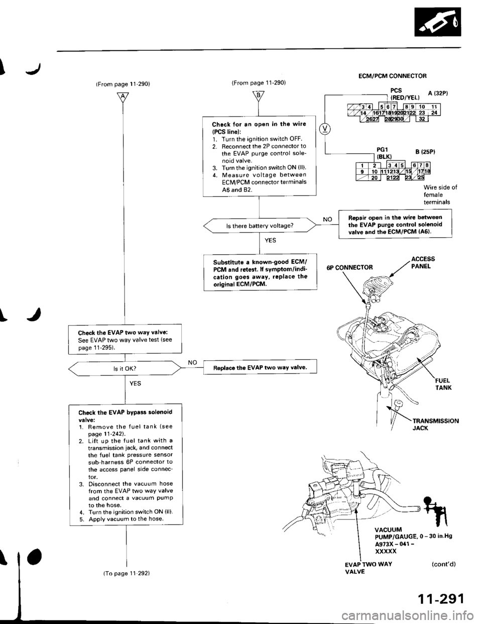
'99 - 00 modols except Dl6Y5 engine with M/T:
The scan tool indicates Diagnostic Trouble Code (DTC) P1456: Evaporative Emission (EVAP) control system leak
detected (fuel tank svstem).
The scan tool indicates Diagnostic Trouble Code (DTC) P1457: Evaporative Emission (EVAP) control system leak
detected (EVAP control canister system).
Possible Cause
. Fuel fill cap
. Vacuum Connections
. FuelTank
. EVAP Control Canister Vent Shut Valve
. EVAP Control Canister Vent Shut Valve Circuit
. EVAP Purge Control Solenoid Valve
o EVAP Purge Control Solenoid Valve Circuit
. EVAP Bypass Solenoid Valve
0 -30 in,Hg
. EVAP Bypass Solenoid Valve Circuit
. Fuel Tank Pressure Sensor
. Fuel Tank Pressure Sensor Circuir
. EVAP Control Canister
. ORVR vent shut valve
. ORVR vapor recirculation valve
. Throttle Body
Troubleshooting Flowchart
VACUUMPUMP/GAUGE,A973X - oal -
xxxxx
T-t
t\
The MIL has been reported on.DTC P1456 o. P1457 is stored.
Check the EVAP cont.ol canistervent shul valve:1. Disconnect the vacuum hosefrom the EVAP three wayvalve and connect a vacuumpump to the hose.2. Remove the EVAP controlcanister vent shut valve fromtne canrster.3. Turn the ignition switch ON (ll).
4. Apply vacuum to the hose.Check for a short in the wiro(VSV linel:Disconnect the 2P connector fromthe EVAP control canister ventDoes the vaive hold vacuum?
RoDair 3hort in the wire botwe€nthe EVAP control canilter ventshut valve and the ECM/PCM{A4t.
Does the valve hold vacuum?Check the EVAP cont.ol canisterv€nl shut valve:1. Turn the ignition switch OFF.2. Connect ECM/PCM connectorterminal A4 to body groundwith a jumper wire.3. Turn the ignition switch ON (ll).
4. Apply vacuum to the hose.
Reolace the EVAP control canis-ter veni shut valve.
Does the valve hold vacuum?
Wire side of female terminals
11-288
lTo page 11-289)
Page 560 of 2189

IECM/PCM CONNECTOR
I
EVAP TWO WAYVALVE
Wire side oftemaleterminals
FUELTANK
(cont'd)
11-291
tn
VACUUMPUMP/GAUGE,0 - 30 in Hs
A973X - 041 -
xxxxx
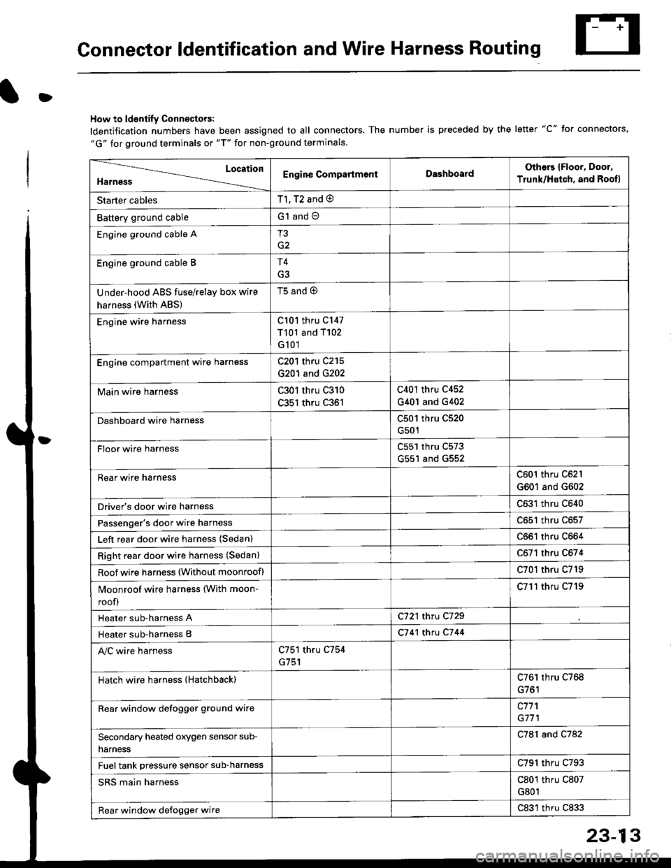
(From page l1 290)
Check the EVAP two way valve:
See EVAP two way valve test (see
page 11-295).
Roplace the EVAP two way valve
Check the EVAP bypa$ solenoid
1. Remove the fuel tank (see
page 11-242J.2. LiIt up the fuel tank with a
transmission iack, and connect
the fuel tank pressure sensor
sub harness 6P connector to
the access panel side connec_
tor,3. Disconnect the vacuum hosefrom the EVAP two way valveand connect a vacuum PumPto the hose,4. Turn the ignition switch ON (ll)
5. Apply vacuum to the hose.
(To page 11 292)
(From page 11-290)
Check for an open in the wire
{PCS lin6):1. Turn the ignition switch OFF
2. Reconnect the 2P connector to
the EVAP purge control sole-
3. Turn the ignition switch ON {ll).4. Measu re voltage betweenEClr/PCM connector terminals
A6 and 82.
Ropair open in the wire betweenthe EVAP purge Gontrol solenoidvrlve and th6 ECM/PCM lA6lls there battery voltage?
Substitute a known-good ECM/
PCM rnd re{61. lf symptom/indi'
cation goes away, rePlace the
oiiginal ECM/PCM.
Page 563 of 2189

Emission Control System
Evaporative Emission (EVAPI Controls (cont'd)
Evaporative Emission (EVAPI Two Way Valve Testing
l'96 DIGYS engine lcoupel,'97 Dl6Y7 engine (coupe: KL
model, sedan: KL (LX) modoll,'97 Dl6Y8 engine {coup€:
alt models, sedan: KL model, '98-all modelsll:
1. Remove the fuel fill cap.
2. Remove the vapor line from the EVAP two way
valve. and connect it to a T-fitting from a vacuum
gauge and a vacuum pump as shown.
VACUUM/PRESSURE
IJ
f96 D16Y5 engine,'96 D16Y7 engine,'96 D16Y8 ongine
(sedanl,'97 D16Y5 engine,'97 Dl6Y7 engine {coupe: KA,
KC models, sedan: KA, KC, KL {DX} models, hatchback:
all modsls),'97 D16Y8 engine {sedan: KA, KC models}l:
1. Remove the fuel fill cap,
2. Remove the vapor line from the EVAP two way
valve on the fuel tank, and connect it to a T-fitting
from a vacuum gauge and a vacuum pump as
snown.
VACUUM/PRESSURE GAUGE,0 - 4 in.Hg07JAZ - 0010008VACUUMPUMP/GAUGE.0 -30 in.HgA973X-041 -XXXXX
Apply vacuum slowly and continuously while watch-
ing the gauge. The vacuum should stabilize momen-
tarily at 0.8 - 2.1 kPa (6 - 16 mmHg, 0.2 - 0.6 in.Hg).
lf the vacuum stabilizes (valve opens) below
0.8 kPa {6 mmHg, 0.2 in.Hg) or above 2.1 kPa
(16 mmHg, 0.6 in.Hg), install a new valve and retest.
Move the vacuum pump hose from the vacuum fit-
ting to the pressure fitting, and move the vacuum
gauge hose from the vacuum side to the pressure
side as shown.
Slowlv pressurize the vapor line while watching the
gauge. The pressure should be stabilize momentari
ly above 1.0 kPa (8 mmHg. 0.3 in.Hg).
. lf the pressure momentarily stabilizes (valve
opens) above '1.0 kPa (8 mmHg, 0.3 in.Hg), the
valve is OK.
. lf the pressure stabilizes below 1.0 kPa (8 mmHg,
0.3 in.Hg), install a new valve and retest.
Apply vacuum slowly and continuously while
watching the gauge. The vacuum should stabilize
momentarily at 0.7 - 2.0 kPa (5 - 15 mmHg, 0.2 - 0.6
in.Hg ).
lf the vacuum stabilizes (valve opens) below
0.7 kPa (5 mmHg,0.2 in.Hg) or above 2.0 kPa
(15 mmHg, 0.6 in.Hg), install a new valve and retest.
Move the vacuum pump hose from the vacuum fit-
'l'
4.
5.
ting to the pressure fitting, and move the
gauge hose from the vacuum side to the
side as shown.
PRESSURESIDE
Slowly pressurize the vapor line while watching the
gauge. The pressure should stabilize at 1.3 - 4.7 kPa
(0 - 35 mmHg, 0.4 - 1.4 in.Hg).
. It the pressure momentarily stabilizes (valve
opens) at 1.3 - 4.7 kPa (10 - 35 mmHg, 0.4 - 1.4
in. Hg), the valve is OK.
. lf the pressure stabilizes below 1.3 kPa (10 mmHg,
0.4 in.Hg) or above 4.7 kPa (35 mmHg. 1.4 in.Hg),
install a new valve and retest.
vacuum
pressure
GAUGE0- 4 in.Hg
T-FITTINGT-FITTING
11-294
\,
Page 564 of 2189

\
Evaporative Emission (EvAPl Two Way Valve T6ting
'99 - 00 modols:
'L Remove the fuel tank (see page 11-242).
2. Remove the vapor line {rom the EVAP two way
valve (located above the EVAP control canister), and
connect it to a T-fitting from vacuum gauge and
vacuum pumo as snown,
VACUUM/PRESSUREGAUGE0 - il in.Hg07JAZ - 001(x)08
ry(L
"*'"""_,";f1
T.FITTING
Apply vacuum slowly and continuously while watch-
ing the gauge.
The vacuum should stabilize momentarily at 0.8 -
2.1 kPa {6 - 16 mmHg, 0.2 - 0.6 in.Hg).
lf the vacuum stabilizes (valve opens) below
0.8 kPa (6 mmHg, 0.2 in.Hg) or above 2.1 kPa
(16 mmHg, 0.6 in.Hg), install a nsw valve and retest.
Move the vacuum pump hose from the vacuum fit-
ting to the pressure fitting, and move the vacuum
gauge hose from the vacuum side to the pressure
side as shown.
GAUGE,0 - 30 in.Hg4973X - (Xl -
xxxxx
J.
5. Slowly pressurize the vapor lin€ while watching the
gauge.
The pressure should be stabilize momentarily
above 1.0 kPa (8 mmHg, 0.3 in.Hg).
. lf the pressure momentarily stabilizes (valve
opens) above 1.0 kPa (8 mmHg, 0.3 in.Hg), the
valve is OK.
. ll the pressure stabilizes below 1.0 kPa (8 mmH9,
0,3 in,Hg), install a new valve and retsst.
(cont'd)
11-295
Page 1483 of 2189

Connector ldentification and Wire Harness Routing
D
How to ldentify Connectors:
ldentification numbers have been assigned to all connectors. The number is preceded by the letter "C" for connectors,"G" for ground terminals or "T" for non-ground terminals.
Location
HarnessEngine CompartmentDashboardOthers {Floor, Door,
Trunk/Hatch, and Rootl
Starter cablesT1, T2 and @
Battery ground cableG1 and O
Engine ground cable AT3
G2
Engine ground cable BT4
Under-hood ABS fuse/relay box wire
harness (With ABS)
t5 ano (9
Engine wire harnessCl01 thru C147
T101 and T102
G101
Engine compartmenl ware harnessC201 thru C215
G201 and G202
Main wire harnessC301 thru C310
C351 thru C361
C401 thru C452
G401 and G402
Dashboard wire harnessC501 thru C520
G501
FIoor wire harnessC551 thru C573
G551 and G552
Rear wire harnessC601 thru C62l
G601 and G602
Driver's door wire harnessC631 thru C640
Passenger's door wire harnessC651 thru C657
Left rear door wire harness (Sedan)C661 thru C664
Right rear door wire harness (Sedan)C671 thru C674
Roof wire harness (Without moonroof)C701 thru C719
Moonroof wire harness {With moon-
roof)
C7l'l thru C719
Heater sub-harness AC721 thru C729
Heater sub-harness BC7 41 thtu C7 44
Ay'C wire harnessC751 thru C754
G751
Hatch wire harness (Hatchback)C761 thru C768
Rear window defogger grgund wirec771
G171
Secondary heated orygen sensor sub-
narness
C781 and C782
Fuel tank pressure sensor sub-harnessC791 thru C793
SRS main harnessC801 thru C807
G801
Rear window defogger wireC831 thru C833
Page 1486 of 2189

Connector ldentification and Wire Harness Routing
Engine Wire Harness lD16Y5, D16Y8 enginss): '96 - 98 models
Connector or
Torminal
Numbsr of
CavitissLocationConnects toNot€s
c 101c102c103c104c104c105c106c107c108c 109c110c111c112c113c114c115c116cl17c118c119c120cl21
c122c123cl23c124
c125
c127c12Ac129c130c131c132c 133c134c135
c136
c138c139c140c 141c142c 143c144cl44c145c'146cl47
10
1
22
14l4322l0I
2
2
2
2120
3l
14
14
1222
2
2
22
Left side of engine compartmentMiddle of engineMiddle of engineLeft side of engine companmentLeft side of engine compartmentMiddle of engineMiddle of engineMiddle of engineMiddle of engineMiddle of enginefvliddle of engineMiddle of engineMiddle of engineMiddle of engineMiddle of engineMiddle of engineMiddle of engineLeft side of engine compartmentMiddle of engineMiddle of engineMiddle of engineMiddle of engine
Middle of engineMiddle of engineMiddle of engineMiddle of engineMiddle of engineMiddle of engineMiddle of engineMiddle of engineMiddle of engineRight side of engine companmentBehind right kick panelUnder right side of dashUnder riOht side of dashUnder right side of dashUnder right side of dashUnder right side of dashUnder right side of dash
Under right side of dash
Under right side of dash
Middle of engineMiddle ot enginel iddle of engineMiddle of engineMiddle of ongineMiddle of engineLeft side of engine compartmentMiddle of engineMiddle of engineRight side of engine compartmentRight side of engine compartmentRight side of engine compartment
USACanada
Afi
USA
-' (A/r)
Main wire harness (C303)Crankshaft speed fluctuation (CKF) sensorEngine oil pressure switchAlternatorAlternatorNo. 'l fuel injectorNo. 2 fuel injectorNo.3 fuel injectorNo. 4 fuel injectorIAC valveThrottle position (TP) sensorl\4anifold absolute pressure (MAP) sensorIntake air temperature (lAT) sensorPower steering pressure {PSPI switchEVAP purge control solenoid valveJunction connectorJunction conn€ctorVehicle speed sensor {VSS}Countershaft speed sensorEngine coolant temp€rature (ECT) switch ADistributorEngine coolant temperature (ECT) sendingunrtEngine coolant temperature (ECT) sensorPrimary HO2S (sensor'l)Primary HO2S (sensor 1)Back-up light switchLock-up control solenoid valveSecondary HO2S (sensor 2)Mainshaft speed sensorLinear solgnoid valveShift control solsnoid valveStarter solenoidJunction connectorMain wire harnesE (C446)ECM/PCMPCMECMiPCMECM/PCMMain wire harness (C305)
Main wire harness (C305)
Main wire harness (C305)
Knock sensor (KS)IAC valveVTEC solenoid valveVTEC pressure switchEVAP control canister vent shut valveEGR control solenoid valveSecondary gear shaft speed sensorEGR valveEGR valveDrive pulley speed sensorSolenoid connector {CVT)Driven pulley speed sensor
*, (M/T)M/T*" INT\
*, tAtf)
NT:'96 model*,(A,/T):'97 - 98mooets
moqets
M/T
-1 (l,/T)*, (A,/T)-,(4,/T)*1 {M/T)*, (A,/T)*1 (CW)*, (A,T)
T101r102Left side of engine companmentRight side of engine companmentAlternatorUnder-hood fuse/relay boxG 101Middle of engineEngine ground, via engine wire harness
2
*1: Dl6Y5 engine*2: D16Y8 engine*3: D16Y5 (Ay'T), D16Y8 engines
3-16