Page 218 of 2189
Ring-to-Groove Clearance
After installing a new set of rings, measure ring-to-
groove clearances:
Top Ring Clearance
Standard (New):
B16A2 angine:
0.045 - 0.070 mm (0.0018 - 0.(X128 in)
Dl6Y5, Dt6Y7, Dl6Y8 engin€s:
0.035 - 0.060 mm {0.0014 - 0.002'l in)
service Limit: 0.13 mm (o.fixi in)
Second Ring Clearance
Standard lNow):
B16A2 engine:
0.0/t0 - 0.065 mm (0.0016 - 0.0026 in)
Dl6Y5, D16Y7, D16Y8 onginos:
0.030 - 0.055 mm (0.(X)12 - 0.0022 in)
Sewica Limh: 0.13 mm (0.005 io)
.,o
Alignment
1. Installthe rings as shown.
NOTE: The manufacturing marks must be facing
upward.
SECOND RING (Darkl
Piston Ring Dimsnsions:
Unit mm (in)
Unit mm (in)
TOP RING (Chrome)
t----T f
lB
t---f_-L
A
Top Ring (Standard)
Second Ring (Standard)
B
Bl642 engine3.1 (0.12)1.0 (0.04)
D16Y5, D16Y7,
D16Y8 engines2.6 (0.10)1.0 (0.04)
B
816A2 engine3.3 (0.13)1.2 (0.05)
D16Y5, D16Y/.
D16Y8 engines3.0 (0.12)1.2 {0.05t
(cont'd)
7-21
Page 220 of 2189

PistonsGrankshaft
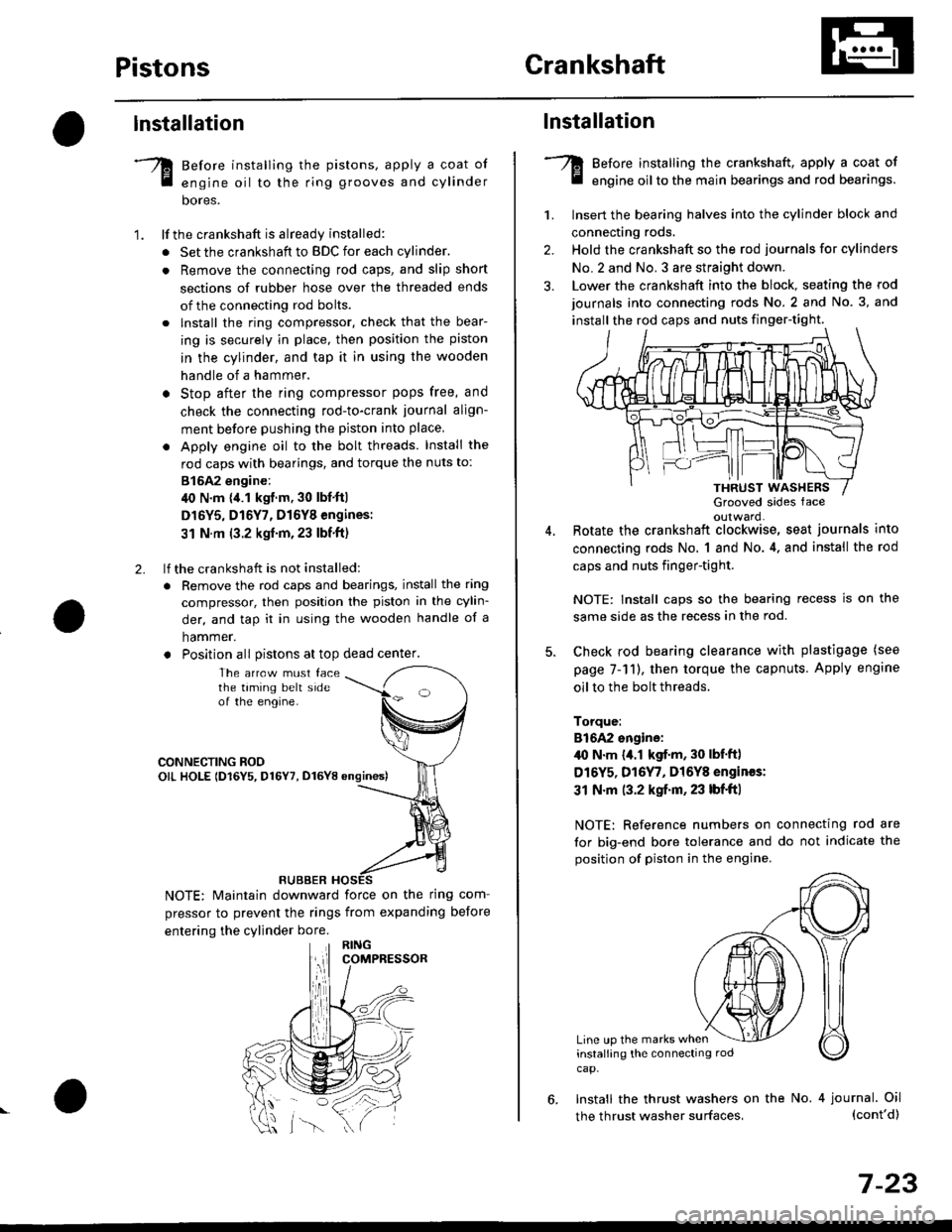
lnstallation
Before installing the pistons, apply a coat of
engine oil to the ring grooves and cylinder
bores.
lf the crankshaft is already installed:
. Set the crankshaft to BDC for each cylinder.
. Remove the connecting rod caps, and slip short
sections of rubber hose over the threaded ends
of the connecting rod bolts.
. lnstall the ring compressor. check that the bear-
ing is securely in place, then position the piston
in the cylinder, and tap it in using the wooden
handle of a hammer.
o Stop after the ring compressor pops free, and
check the connecting rod-to-crank journal align-
ment before pushing the piston into place
. Apply engine oil to the bolt threads. Install the
rod caps with bearings, and torque the nuts to:
815A2 engine:
40 N.m {,1.1 kgf.m, 30 lbf'ft|
D16Y5, D16Y7, D16Y8 engines:
31 N.m (3.2 kgf'm,23 lbf'ft)
lf the crankshaft is not installed:
. Remove the rod caps and bearings, install the ring
compressor, then position the piston in the cylin-
der, and tap it in using the wooden handle of a
hammer.
. Position all Distons at top dead center.
1.
2.
The arrcw must facethe taming belt sideof the engine.
CONNECTING ROOOIL HOLE lD16Y5, D16Y7, D16YB ongines)
NOTE: Maintain downward force on the ring com-
pressor to prevent the rings from expanding before
entering the cylinder bore.
RUBBER
,lll
lnstallation
Before installing the crankshaft, apply a coat of
engine oil to the main bearings and rod bearings.
Insert the bearing halves into the cylinder block and
connecting rods.
Hold the crankshaft so the rod journals for cylinders
No.2 and No. 3 are straight down.
Lower the crankshaft into the block, seating the rod
journals into connecting rods No. 2 and No. 3, and
install the rod caps and nuts finger-tight.
1.
2.
3.
5.
Grooved sides faceoulward.Botate the crankshaft clockwise, seat journals into
connecting rods No, 1 and No.4, and install the rod
caps and nuts finger-tight.
NOTE: Install caps so the bearing recess is on the
same side as the recess in the rod.
Check rod bearing clearance with plastigage (see
page 7-11), then torque the capnuts. Apply engine
oil to the bolt threads.
Torque:
816A2 sngine:/l{, N.m {a.l kgf.m, 30 lbf'ftl
D16Y5, D16Y7, Dl6Y8 engines:
31 N.m (3.2 kgf.m, 23 lbf'ft|
NOTE: Reference numbers on connecting rod are
for big-end bore tolerance and do not indicate the
position of piston in the engine.
Line up the marks wheninstalling the connectrng rod
cap.
6. Install the thrust washers on the No. 4 journal. Oil(cont'd)
7-23
the thrust washer surfaces,
Page 221 of 2189

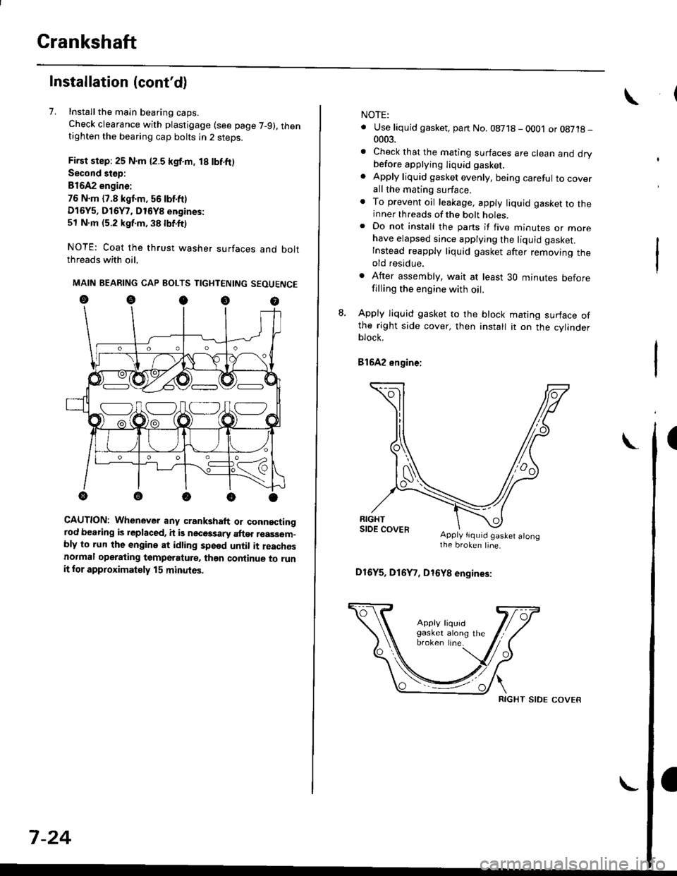
Crankshaft
Installation (cont'd)
7. Installthe main bearing caps.
Check clearance with plastigage (see page 7-9), thentighten the bearing cap bolts in 2 steps.
First step: 25 N.m {2.5 kgf.m, 18 lbf.ft)
Second stop:
B1642 engine:
76 N.m {7.8 kgf.m, 56 lbf.ft)
D16Y5, D16Y7, D16Y8 engines:
51 N.m (5.2 kgf.m, 38 lbf.ft)
NOTE: Coat the thrust washer surfaces and boltthreads with oil.
MAIN BEARING CAP BOLTS TIGHTENING SEOUENCE
oocoo
CAUTION: Whenever any crankshaft or connectingrod bearing is replaced, it is necGssary after reassom-bly to run the engine at idling spe6d until it reachesnormal operating temperature, than continue to runit for approximately 15 minutos.
:V fr\-/.---\-/.-
7-24
NOTE:
. Use liquid gasket, part No. 08718 - 0001 or08718-0003.
. Check that the mating surfaces are clean and drybefore apptying liquid gasket.
. Apply liquid gasket evenly, being careful to coverall the mating surface.. To prevent oil leakage, apply liquid gasket to theinner threads of the bolt holes.. Do not install the parts if five minutes or morehave elapsed since applying the liquid gasket.
Instead reapply liquid gasket after removing theold residue.
. After assembly, wait at least 30 minutes beforefilling the engine with oil.
L Apply liquid gasket to the block mating surface ofthe right side cover, then install it on the cylinderblock.
Bl6A2 engine;
Apply tiquid gaslet alongthe broken line.
D16Y5, D16Y7, D16Y8 engines:
RIGHT SIDE COVER
Page 223 of 2189
CrankshaftOil Pan
Installation (cont'd)
NOTE:
. Apply a light coat of oil to the crankshaft and iothe lip of seal.. Use new O-rings and apply oil when installingthem.
10. lnstallthe oil screen.
816A2 engine:
6 x 1.O mml l N'm (1 .1 kgl.m,8 tbt.Irl
,.//
{ / cor*rt(..ao Replace.
t(^^
11 N.m 11 .1 kgf.m,a lbl'ltl ,/.rB tbt4tl /
*P/
& ^/t
O.RINGReplace.
OtL PutitP
D16Y5, D16Y7, D16Y8 engines:
24 N.m (2.4 kgf.m,'17 lbl.fr)
kgf.m,
OIL SCREEN
6 x 1.0 mm1 1 N.m {1 .1 kgf.m,
6x1.0mm11 N.m {1.18 tbt.rr)
I
Ia lbf.fr)
DOWEL PIN
rT
lle/ OIL PUMP6 x 1.0 mm11 N.ml l.1 kgf'm, a lbf.frl
7-26
Installation
D16Y5, Dl6Yg engines:
1. Install the oil pan gasket on the oil pan.
OIL PANGASKETReplace.
OIL PAN
I
Page 224 of 2189

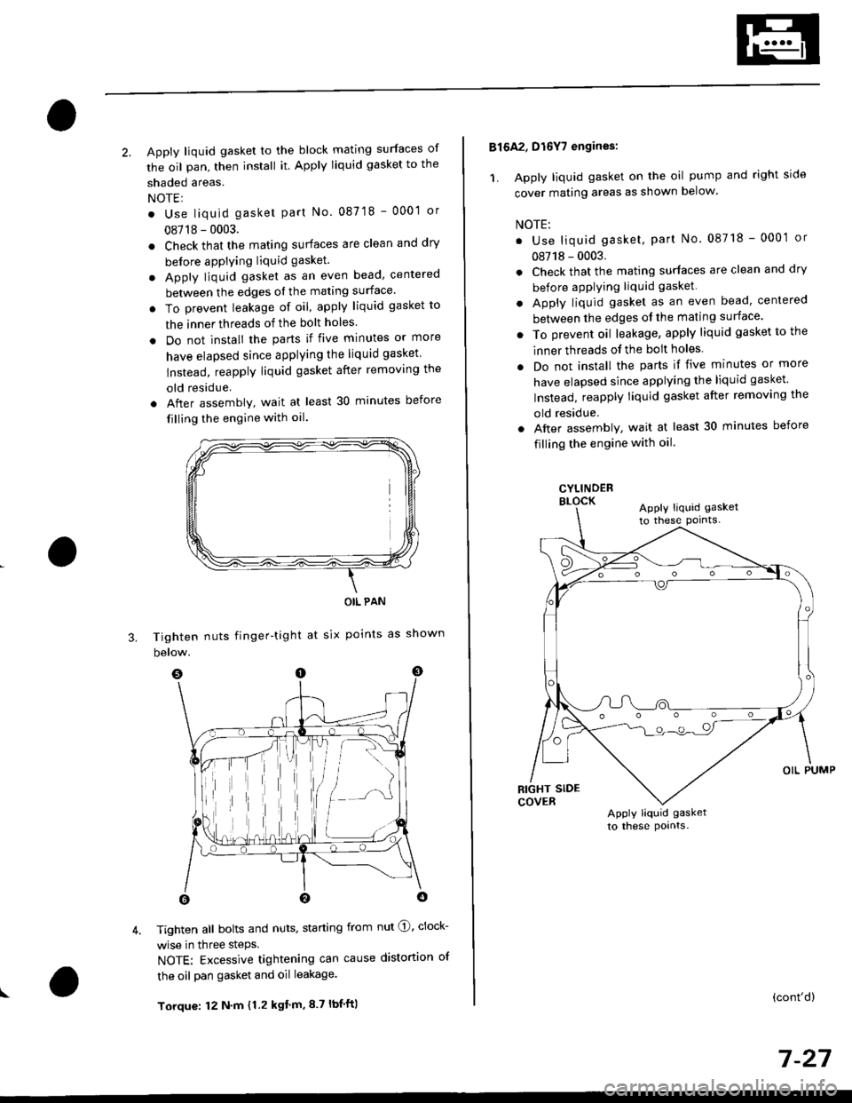
2. Apply liquid gasket to the block mating surfaces of
the oil pan, then install it. Apply liquid gasket to the
shaded areas.
NOTEI
. Use liquid gasket part No. 087 18 - 0001 or
08718 - 0003.
. Check that the mating surfaces are clean and dry
before apPlying liquid gasket.
. Apply liquid gasket as an even bead, centered
between the edges ol the mating surface'
. To prevent leakage of oil, apply liquid gasket to
the inner threads of the bolt holes
. Do not install the parts if five minutes or more
have elapsed since applying the liquid gasket
lnstead, reapply liquid gasket after removing the
old residue
. After assembly, wait at least 30 minutes before
filling the engine with oil.
Tighten nuts finger-tight
below.
OIL PAN
at six points as shown
I
3.
4. Tighten all bolts and nuts, starting from nut @, clock-
wise in three steps.
NOTE: Excessive tightening can cause distortion of
the oil pan gasket and oil leakage.
Torque: 12 N'm {1.2 kgt'm,8.7 lbf'ft|
816A2, D16Y7 engines:
1. Apply liquid gasket on the oil pump and right side
cover mating areas as shown below.
NOTE:
. Use liquid gasket, part No. 08718 - 0001 or
08718 - 0003.
. Check that the mating surfaces are clean and dry
before applying liquid gasket
. Apply liquid gasket as an even bead, centered
between the edges ol the mating surface'
. To prevent oil leakage, apply liquid gasket to the
inner threads of the bolt holes
. Do not install the parts if five minutes or more
have elapsed since applying the liquid gasket
Instead, reapply liquid gasket after removing the
old residue.
. Aftel assembly, wait at least 30 minutes before
filling the engine with oil.
CYLINDERELOCKApply liquid gasket
to these pornts-
Apply liquid gasket
to these pornts.
(cont'd)
7 -27
Page 230 of 2189
lllustrated Index
(cont'dl
NOTE:
. Use new O-rings when reassembling.. Apply oil to O-rings before instaltal|on.. Use liquid gasket, Part No. 08718 0001 or 0e7190003.
. Clean the oil pan gasket mating surfaces before install_ing.
. Apply liquid gasket to the recesses of the oil pan gasket (see page 7-27).
D16Y7 €ngine:
OIL PUMPOverhaul, page 8-12Inspection, page 8 13Apply liquid gaskerto the mating surfaceof the block.
DOWEL PIN
CAUTION: Do not overtighten the drain bolt.
ENGINE OIL PBESSURE SWITCH18 N.m (1.8 kgtm, 13 tbt.trl1/8 in. BSPT (BritishStandard Pipe Taper)28 threads/inch. Useproper liquid sealant.
O-BINGReplace.
OIL BREATHERCHAMBER
6x1.0mm'11 N.m { 1.1 ksnm,8 tbtft)
6x1.0mm1l N.m {1.1 kgf-m,8 tbf.ftl
ll
OIL PANGASKETBepiace.
OIL PANRefer to page 7-27when installing.
6x1.0mm11 N m (1.1 kgt.m,8 tbl.ftlApply liquid gasket to
6 x 1.0 mml2 N.m {1.2 kgtm, 8.7 tbf.ft)
DRAIN BOLT44 N.m {4.5 kgtm, 33 tbf.ft}Do not ovenighten.
a
8-4
Page 232 of 2189
Engine Oil
Inspection
1.Park the vehicle on level ground, and turn off theengine. Allow the oil a few minutes to drain backinto the oil pan so the dipstick will show the actuallevel.
Make certain that the oil level indicated on the dip_stick is between the upper and lower marks.
lf the level has dropped close to the lower mark.add oil until it reaches the upper mark.
CAUTION: lmert thc dipstick car€fully to avoid b€nd_ing it.
Bl6A2 angin.:
,,7.fp--)*,".
rowrn-u l
D16Y5, D16Y7, Dt6y8 ongines:
8-6
Replacement
CAUTION: Removo the drain boli carefully while lhoengine is hot; the hot oil may causo scalding.
:1. Warm up the engine.
2. Drain the engine oil.
81642, D16Y7 engin€s:
{rl N.m (4.5 kgf.m,33 tbt ft}Do not overtighten.
D16Y5, Dl6Y8 6ngin93:
WASHER
DRAIN BOLT39 N.m 14.0 kgfm, 29 tbf,f0uo not overtighten.
DRAIN BOLT
Page 238 of 2189
Oil Pump
Overhaul (cont'dl
NOIE:
. Use new O rings when reassembling.. Apply oil to O rings before instalraUon.. Use liquid gasket, Parr No. 08718 - 0001 or08718_0003.. The rotors must be installed to the same direction.. After reassembly, check that the rotors move without binding.
D16Y5, D16Y7, D16Y8 engines:
(
6x1.0mm7 N.m (0.7 kgI.m, 5 lbf ftl
PUMP HOUSINGInspection, page 8 13Apply liquid gasketto mating surface ofthe cylinder biockwhen installing.
INNER ROTORInspectron, page 8 13
DOWEL PIN
PUMP COVEB
O-RING
_.feor,""
\6x1.0mm11 N.m {1.1 kgf.m,8lbl.ft)RELIEF VALVEValve must slide freelyin housing bore.Replace if scored
OIL SEAL
[".?li;:;"". *,", ,.rg
""rc
@.-*or"."
9''ggttt*
8-12