Page 239 of 2189

4.
Removal/lnspection/lnstallation
2.
3.
1.
5.
6.
1.
8.
Drain the engine oil.
Turn the crankshaft and align the white groove on
the crankshaft pulley with the pointer on the lower
cover.
Remove the cylinder head cover and upper cover'
Remove the power steering pump belt, air condi-
tioner beit and the alternator belt
Remove the crankshaft pulley and remove the lower
cover.
Remove the timing belt.
Remove the drive pulley.
Remove the oil pan and oil screen.
O.RINGReplaceOOWEL PIN
OIL SCREEN
9. Remove the oil PumP.
!'a
10.Remove the screws from the pump housing, then
separate the housing and cover'
Check the inner-to-outer rotor radial clearance on
the pump rotor. lf the inner-to outer rotor clearance
exceeds the service limit, replace the inner and
outer rotors.
lnner Rotor-to-Outer Rotor Radial Clearance
Standard {New}: 815A2 engine 0.04 - 0.16 mm
(0 002 - 0'006 in)
D16Y5, D16Y7, D16Y8 engines
0.02 - 0.14 mm 10.001 - 0.006 in)
Service Limit: 0.20 mm (0 008 inl
OUTER ROTOR
INNER ROTOR
Check the housing-to-rotor axial clearance on the
pump rotor. lf the housing-to rotor axial clearance
exceeds the service limit, replace the set of inner
and outer rotors and/or the pump housing
Housing-to-Rotor Axial Clearance
Standard (N€w): 816A2 engine 0.02 - 0.07 mm
(0.001 - 0.003 inl
D16Y5, D16Y7, D16Y8 engines
0.03 - 0.08 mm (0.001 - 0.003 inl
S€rvice Limit: 0.15 mm 10.006 in)
11.
't2.
(cont'd)
8-13
Page 240 of 2189

Oil Pump
RemovaUlnspection/lnstallation (cont'dl
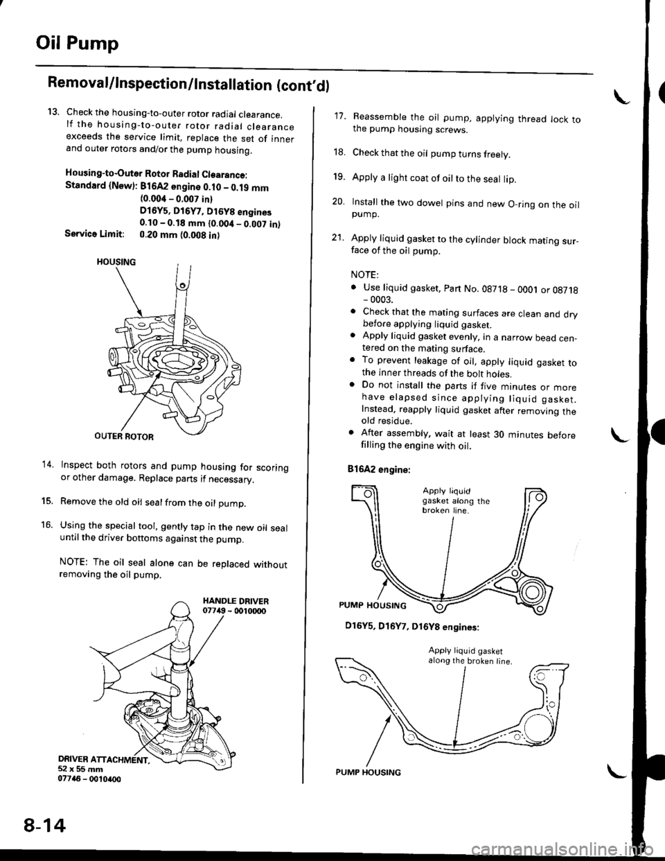
13. Check the housing-to-outer rotor radial clearance.lf the housing-to-outer rotor radial clearanceexceeds the service limit, replace the set of innerand outer rotors and/or the pump housing.
Housing-to-Outer Rotor Badial Clearanco:Standard {Newl: 816A2 sngine 0.10 - 0.19 mm(0.004 - 0.007 in)
D16y5, Di6y7, Dt6y8 engines0.10 - 0.18 mm {0.00it _ 0.007 in)Service Limit: 0.20 mm (0.008 in)
lnspect both rotors and pump housing for scoringor other damage. Replace parts if necessary.
Remove the old oil sealfrom the oil pump.
Using the special tool, gently tap in the new oil sealuntil the driver bottoms against the pump.
NOTE: The oil seal alone can be replaced withoutremoving the oil pump.
DRIVER ATT52x55mm077a6 - 0010ao0
14.
15.
16.
8-14
PUMP HOUSING
17. Reassemble the oil pump, applying thread lock tothe pump housing screws.
18. Check that the oil pump turns freely.
19. Apply a light coat of oilto the seal lip.
20. Install the two dowel pins and new O-ring on the oilpump.
21. Apply liquid gasket to the cylinder block mating sur_face of the oil pump.
NOTE:
. Use liquid gasket, Part No.08718 - oOOj or 08718- 0003.. Check that the mating surfaces are clean and drybefore applying liquid gaskel. Apply liquid gasket evenly, in a narrow bead cen-tered on the mating surface.o To prevent leakage of oil, apply liquid gasket tothe inner threads of the bolt holes.. Do not install the parts if five mtnures or morehave elapsed since applying liquid gasket.Instead. reapply liquid gasket after removing theold residue.
. After assembly, wait at least 30 minutes beforefilling the engine with oil.
81642 engine:
\
D16Y5, D16Y7, D16Y8 engines:
along the broken line.
Page 241 of 2189
22. Installthe oil pump on the cylinder block.
Apply grease to the lip ot the oil pump seal.
Then. install the oil pump onto the crankshaft.
When the pump is in place, clean any excess grease
off the crankshaft and check that the oil seal lip is
not distorted.
81642 engine:
8 x 1.25 mm6x1.Omm
24 N.m (2.i4 kg[.m,17 tbl.trl
11 N.m {1.1 kg{.m,8 rbt ft)O.RI GReplace.
DOWEL PINS
GASKETReplace.
OIL SCREEN
6x1.0mmrl N.m {1.1 kgf'm,I tbf.ftl
D16Y5, D16Y7. D16Y8 enginos:
OOWEL PIN
6x1.0mm11N'm (1.1 kgf m'
O.RINGReplace.
DOW€L PIN
GASKETReplace.
6x1.0mm
6 x 1.0 mm '11 N'm {1 1 kgf'm,
11 N.m (1.1 kgf.m, I lbf ftl
8 lbf.ft)
!o
8-15
lnstall the oil screen.
Install the oil pan (see pages 7-26 or 7-27).
NOTE: Clean the oil pan gasket mating surfaces.
Page 243 of 2189
Intake Manifold
Replacement
NOTE: Use new O-rings and gaskets when reassemblinq.
CAUTION:
. Check tor folds or scratchos on the surface of tbe gasket.. Replace with a now gasket if damaged.
D16Y7 engine:
8 x 1.25 mm22 N.m 12.2 kgtm, 16 tbtftl
INTAKE MANIFOLDReplace if cracked orif mating surfaces aredamaged.
8 x 1.25 mm23 N.m {2,3 kgt m.17 rbf.ftl
INTAKE MANIFOLDBRACKET
8 x 1.25 mm24 N.m {2.4 kgf.m, 17 tbf.ftl
9-2
Page 247 of 2189
Exhaust Manifold
Replacement
NOTE: Use new gaskets and self-locking nuts when reassembling.
CAUTION:
. Check for folds or scratch€s on the surface of the gasket.
. Replace with a new gasket it damaged.
D16Y5. D16Y7 engines:
I x 1.25 mm24 N.m {2.4 kgt.m, 17 tbtft}
MANIFOLDBRACKET
PRIMARY HEATEDOXYGEN SENSORIPRIMAFY HO2SI44 N.m {4.5 kgf m, 33 lbtft)Replacement, page 9-12
GASKETReplace.
I x 1.25 mm31 N.m (3.2 kgf.m,23 tbf.ft)Beplace.
WAY CATALYTICCONVERTER {TWCIlnspection, page 9'12
6x1.0mm11 N.m {1.1 kgt m,8 lbf.ft)
SECONDARY HEATEDOXYGEN SENSOR(SECONDARY HO2S}44 N.m 14.5 kgf.m,33 lbf.ft)Replacement, page 9-13
9-6
Page 250 of 2189
Exhaust Pipe and Muffler
\
Replacement
NOTE: Use new gaskets and self-locking nuts when reassembling
D16Y5, D16Y7 engines:
HEAT SHIELO
6x1.0mm9.8 N.m tl.0 kgf'm,7.2lbf'ft)
EXHAUST PIPE B
EXHAUST PIPE TIP
/
O
6x1.0mm9.8 N.m 11.0 kgt m, 7.2 lbf'ftl
oP----------------8 x 1.25 mm22 N.m 12.2 kg .m,
16 tbf.f Replace.Tighlen the bolts insteps, alternatingside to-side.
8 x 1.25 mm22 N.m 12.2 kgl'm, 16lbl'ttl
Replace.Tighten the bolts in steps,
alternating side-to-side
GASKETReplace.
SELF-LOCKING NUT
8 x 1.25 mm16 N.m 11.6 kgt m, 12 lbt'ftl
Replace.
(cont'd)
9-9
MUFFLER
neOlace. ----------"+@
SELF.LOCKING NUT10 x 1.25 mm33 N.m (3.4 ksd.m,25 lbf.frlReplace.
Page 253 of 2189
TWCHO2S
Inspection
l. Using a flashlight, make a visual check for plugging,
melting and cracking of the catalyst.
D16Y5, D16Y7 engines:
816A2, D16Y8 engines:
-\6{-)\
lT
a
A
FLASHLIGI{T
9-12
Replacement
Primary HO2S:
1. Remove the primary HO2S.
D16Y5, D15Y7 engines:
a. Disconnect the primary HO2S connector, thenremove the cover.
8 x'1.25 mm24 N.m {2.4 kgl.m,
PRIMARY H02SCONNECTOR
b. Remove the primary HO2S.
| \l ,l(
I bK/l
l llw.
/
(
PBIMARY HO2S44 N m (4.5 kgf.m, 33 tbI.ft)
Page 257 of 2189

lllustrated Index
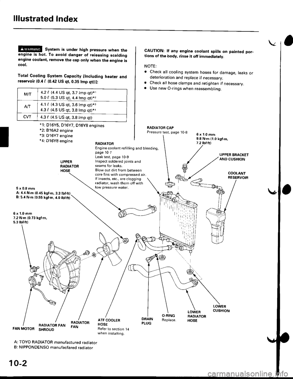
@@ system is under high pressure when theengine is hot. To avoid dangsr of rsleasing scaldingengine coolant, removo the cap only when the engine iscoot.
Total Cooling System Capacity flncluding heater andfoservoir (0.4 f (0.42 US qt, 0.35 tmp qt)ll:
*2: 81642 engine*3: D16Y7 engine*4: D16Y8 engine
CAUTION: lf any engine coolant spills on painted por-tions of the body, rinse it off immediately.
NOTE:
. Check all cooling system hoses for damage, leaks ordeterioration and replace if necessary.. Check all hose clamps and retighten if necessary.. Use new O-rings when reassembling.
RADIATOR CAPPressure test, page '10 86x1.0mm9.8 N.m {1.0 kgtm,7.2 tbt.ltl
UPPERRADIATORHOSE
UPPER BRACKETAND CUSHION
COOLANT
RAOIATOREngine coolant refilling and bleeding,page 10 7Leak test, page 10-9Inspect soldered joints andseams for leaks,Blow out dirt Irom betweencore fins with compressed air.lf insects, etc,, are cloggingradiator, wash them off withrow pressure water.
RESERVOIR
5x0.8mmA: ,1.4 N.m {0.45 kgf.m, 3.3 tbtftlg: 5.4 N.m (0.55 kgtm.4.0 tbf.ft)
6x1.0mm7.2 N.m (0.73 kgt.m,5.3 tbtftl
LOWERCUSHION
RADIATOR FANBADIATORFAN
DRAINPLUG
O-RINGReplace.
LOWEBRADIATORHOSE
FAN MOTOR SHROUD
Ar TOYO RADIATOR manufactured radiatorB: NIPPONDENSO manufacfared raoraror
10-2
Refer to section 14when installing.
Mt-|-4.2 f (4.4 US qt,3.7 tmp qt)*j
5.0 / (5.3 U$ q1, 4.4 16p q11*z
4.1 f (4.3 US qt, 3.6 lmp q0*3
4.31 (4.5 US qt, 3.8 tmp qt)*a
CVT4.3 f (4.5 US qt,3.8 Imp qt)
*1i D16Y5, D16Y7, D16Y8 engines
iil