Page 709 of 2189

L
E Position
The flow of fluid through the torque convefter circuit is the same as in E position The line pressure (1) changes to the
line pressure (3) and flows to the l-2 shift valve. The iine pressure (3) changes to the line pressure (3') at the 'l-2 shift valve
and flows to the servo valve. The servo valve is moved to the right side (Reverse range position) and uncovers the port to
allow line pressure {3") to the manual valve, The line pressure {3') from the 1-2 shift valve flows through the servo valve to
the manual valve and changes the 4th clutch pressure (40). The 4th clutch pressure (40) is applied to the 4th clutch, and
the 4th clutch is engaged,
Reverse Inhibitor Control
When the E position is selected while the vehicle is moving forward at spe€ds over 6 mph (10 km/h)' the PCM outputs the
1st speed signal to shift control solenoid valves A and B; shift control solenoid valve A is turned oFF, shift control solenoid
valve B is turned ON. The 1-2 shift valve is moved to the right side and covers the port to stop line pressure (3') to the
servo valve. The line pressure (3'�) is not applied to the servo valve, and the 4th clutch pressure (40) is not applied to the
4th clutch, as a result, power is not transmitted to the reverse direction'
When used. 'left" or "right" indicates direction on the hydraulic circuit'
14-31
Page 710 of 2189
Description
Hydraulic Flow (cont'd)
lll Position
The flow of fluid through the torque converter circuit is the same as in E position. The line pressure (1) changes to theline pressure (3) and flows to the l-2 shift valve. The line pressure (3) changes to the line pressure (3,) at the 1-2 shift valveand flows to the servo valve. The servo valve is moved to the right side (Reverse range position) and uncovers the port toallow line pressure (3") to the manual valve as in @ position. The line pressure (3") from the servo valve is Intercepted bythe manual valve. However, hydraulic pressure is not supplied to the clutches, and the power is not transmitted.
NOTE: When used, "|eft" or "right" indicates direction on the hydraulic circuit.
14-32
Page 711 of 2189
\
Lock-up System
Lock-up Clutch
1. Ooeration (clutch onl
with the lock-up clutch on, the fluid in the chamber between the torque converter cover and the lock-up piston is drained
off, and the converter fluid exerts pressure through the piston against the torque converter cover, As a result, the conven-
er turbine is locked to the convefter cover. The effect is to bypass the converter, thereby placing the vehicle in direct drive
LOCK.UP PISTONDAMPER SPRING
The power flows by way ot:
Engine
{
Drive plate
i
Torque converter cover
I
Lock-up piston
Damper spring
I
Turbine
Mainshaft
ODeration {clutch off}
With the lock-up clutch off, the fluid flows in the reverse of "clutch on." As a result, the lock-up piston moves away from
the converter cover, and the torque converter lock-up is releassd.
Engine
t
Drive plate
I
Torque convener cover
{
Pump
I
Turbine
Mainshaft
TOROUECOVER
(cont'd)
COI{VERTER
\
TURBNE
MAINSHAFT
14-33
Page 713 of 2189
I
TOROUE CONVERTER
No Lock-up
. Lock-up Control Solenoid Valve A: OFF
. Lock-up Control Solenoid Valve B: OFF
. Linear Solenoid Pressure: High
The pressurized fluid regulated by the modulator works
on both ends of the lock-up shift valve. Under this condi-
tion, the pressures working on both ends of the lock-up
shift valve are equal, the lock-up shift valve is moved to
the right side by the tension of the valve spring alone.
The fluid from the ATF pump will flow through the left
side of the lock-up clutch to the torque convener; that is,
the lock-up clutch is in OFF condition.
NOTE: When used, "left" or "right" indicates direction
on the hydraulic circuit.
MOOULATOR PRESSURE
LINEAR SOLENOIO PRESSURE
(cont'd)
LOCK.UP CONTROLSOLENOID VALVE
RELIEF VALVE
LOCK-UP TIMINGVALVE
9 L ] I COOLER RELIEF VALVE
ATF PUMP
14-35
Page 714 of 2189

Description
Lock-up System (cont'dl
TOROUE CONVERTER
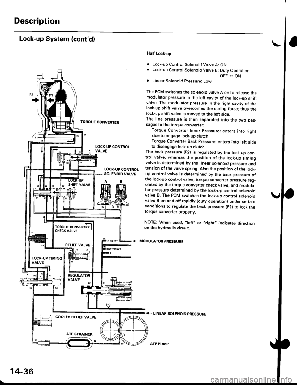
Half Lock-up
. Lock-up Control Solenoid Valve A: ONLock-up Control Solenoid Valve 8: Duty Operation
OFF - ONLinear Solenoid Pressure: Low
The PCM switches the solenoid valve A on to release themodulator pressure in the left cavity of the lock_up shiftvalve. The modulator pressure in the right cavity of thelock-up shift valve overcomes the spring force; thus thelock-up shift valve is moved to the left side.The line pressure is then separated into the two pas-sages to the torque converter:
Torque Converter Inner pressure: enters into rightsade to engage lock-up clutch
Torque Converter Back pressure: enters into left sideto diseogage lock-up clutchThe back pressure (F2) is regulated by the lock-up con-trol valve, whereas the position of the lock-up timingvalve is determined by the linear solenoid Dressure andtension of the valve spring. Also the position of the lock_up control valve is determined by the back pressure ofthe lock-up control valve, torque converter pressure reg_ulated by the torque converter check valve, and modula_tor pressure determined by the lock-up control solenoidvalve B. The PCM switches the lock-up control solenoidvalve B on and off rapidly {duty operation} under certainconditions to regulate the back pressure (F2) to lock thetorque convener properly.
NOTE: When used, "left" or "right" indicates directionon the hvdraulic circuit.
MODULATOR PRESSURE
LINEAR SOLENOTD PRESSURE
LOCK.UP CONTROLVALVE
LOCK.UP CONTROLSOI.TNOID VALVE
A8
TOROUE CONVERTERCHECK VAI-VE
RELIEF VALVE
LOCK-UP TIMINGVALVE
^ L____J'r cooLER RELTEF valvE
14-36
ATF PUMP
Page 715 of 2189

TOROUE CONVERTER
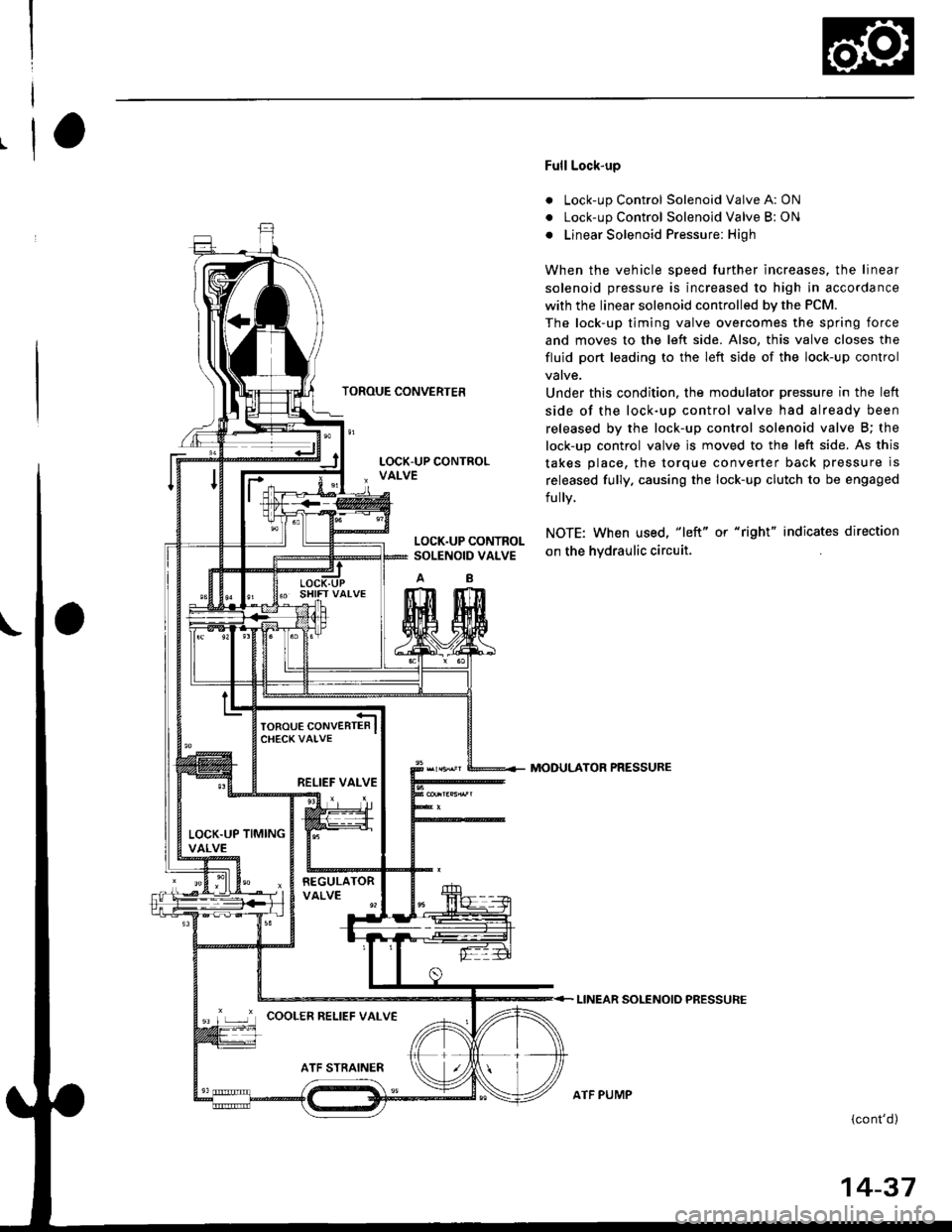
Full Lock-up
. Lock-up Control Solenoid Valve A: ON
. Lock-up Control Solenoid Valve B: ON
o Linear Solenoid Pressure: High
When the vehicle speed further increases. the linear
solenoid pressure is increased to high in accordance
with the linear solenoid controlled bv the PCM.
The lock-up timing valve overcomes the spring force
and moves to the left side. Also, this valve closes the
fluid port leading to the left side of the lock-up control
Under this condition. the modulator pressure in the left
side of the lock-up control valve had already been
released by the lock-up control solenoid valve B; the
lock-up control valve js moved to the left side. As this
takes place, the torque converter back pressure is
released fully. causing the lock-up clutch to be engaged
fully.
NOTE: When used, "|eft" or "right" indicates direction
on the hvdraulic circuit.
MODULATOR PRESSURE
LINEAR SOLENOIO PRESSURE
{cont'd)
LOCK.UP CONTROLSOLENOID VALVE
RELIEF VALVE
LOCK.UP TIMINGVALVE
'r ,-.r' cooLER RELTEF vALvE
ATF PUMP
14-37
Page 716 of 2189
Description
Lock-up System (cont'dl
TOROUE CONVERTER
Deceleration Lock-up
. Lock-up Control Solenoid Valve A: ON. Lock-up Control Solenoid Valve B: Duty Operation
OFF - ONa Linear Solenoid Pressure: Low
The PCM switches solenoid valve B on and off rapidly
under certain conditions. The slight lock-up and half
lock-up regions are maintained so as to lock the torque
converter properly.
NOTE: When used, "left" or "right" indicates direction
on the hydraulic circuit,
MOOULATOR PRESSURE
LINEAR SOLENOID PRESSURE
LOCK-UP CONTROLSOLENOID VALVE
RELIEF VALVE
LOCK.UP TIMINGVALVE
COOLER RELIEF VALVE
ATF STRAINER
1434
ATF PUMP
Page 719 of 2189
SERVICE CHECK CONNECTOR
LOCK -UP CONTROLSOLENOIO VALVEASSEMELY
RED WHT
tlll'
IT
tl
ll
Lo-l
MAINSHAFTSPEED SENSOR
TBRNiBLK
I
I
I-
G 101
NCSG ILS - ILS + ISH A ISH B ltc A ltc B
SHIF'CONTROLSOTENOID VALVEASSEMEI-Y
PCM Terminel Locations
14-41