Page 574 of 2189

Pressure Plate
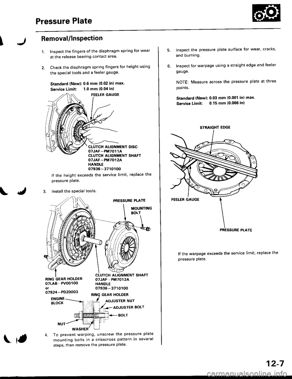
\Removal/lnsPection
1.Inspect the fingers of the diaphragm spring for wear
at the release bearing contact area.
Check the diaphragm spring fingers for height using
the special tools and a feeler gauge.
Standard {New}: 0.6 mm (0.02 inl max.
Seruice Limit: 1.0 mm {0.04 in}
FEELER GAUGE
CLUTCH ALIGNMENT DISCOTJAF_PM7O1 1ACLUTCH ALIGNMENT SHAFTOTJAF-PM7012AHANDLE07936-37tOtOO
lf the height exceeds the service limit, replace the
pressure Plate.
3. Installthe special tools
PRESSURE PLATE
MOUNTINGBOLT
ALIGNMENT SHAFTOTJAF-PM7012AHANDLE07936-371010Oo7924-PD20003GEAR HOLDER
07LA8-PVOOIOOot
ENGINEBLOCKADJUSTER BOLT
BOLT
4. To prevent warping, unscrew the pressure plate
mounting bolts in a crisscross pattern in several
steps, then remove the pressure plate.
f
12-7
lnspect the pressure plate surface for wear' cracks,
and burning.
Inspect for warpage using a straight edge and leeler
ga uge.
NOTEr Measure across the pressure plate at three
pornrs.
Standard (Newl: 0.03 mm (0.001 inl max.
Service Limit: 0.15 mm (0.006 inl
lf the warpage exceeds the service limit, replace the
pressure plate.
STBAIGHT EDGE
Page 576 of 2189

Flywheel
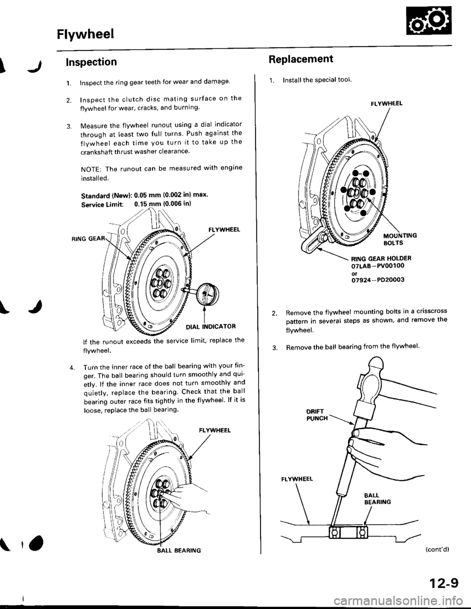
\Inspection
1.
2.
3.
Inspect the ring gear teeth for wear and damage
Inspect the clutch disc mating surface on the
flywheel for wear, cracks, and burning.
Measure the flywheel runout using a dial indicator
through at least two full turns Push against the
flywheel each time you turn it to take up the
crankshaft thrust washer clearance.
NOTE: The runout can be measured with engine
installed.
Standard (New): 0.05 mm (0.002 inl max.
Service Limit: 0.15 mm {0.006 in)
FLYWHEEL
OIAL INOICATOR
FLYWHEEL
lf the runout exceeds the service limit. replace the
flywheel.
Turn the inner race o{ the ball bearing with your tin-
ger. The ball bearing should turn smoothly and qui
etly. lf the inner race does not turn smoothly and
quietly, replace the bearing. Check that the ball
bearing outer race fits tightly in the flywheel. lf it is
loose. replace the ball bearing
IJ
4.
BALL BEARING tO
Replacement
1. Installthe special tool.
MOUNTINGBOLTS
RITIG GEAR HOLDER
oTLAB-PV00100oto7924-PD20003
2.Remove the flywheel mounting bolts in a crisscross
pattern in several steps as shown, and remove the
flywheel,
Remove the ball bearing from the flywheel
(cont'dl
12-9
FLYWHEEL
t\
m\J
Page 577 of 2189
FlywheelClutch Disc, Pressure Plate
Replacement (cont'dl
4. Drive the new ball bearing into the flywheel using
the special tools as shown.
DRIVER07749-0010000
ATTACHMENT,32x35mm07746-OOIOTOO
FLYWHEEL
BEARING
Align the hole in the flywheel with the crankshaft
dowel pin and install the flywheel. Install the
mounting bolts finger-ti9ht.
Install special tool, then torque the flywheel mount-
ing bolts in a crisscross pattern in several steps as
snown.
5.
6.
MOUNTING BOLTS118 N.m (12.0 kgl.m,87 tbf.ft)
RING GEAR HOLDER07LAB-PV00100ol07924 -PO20003
WVa// ,
12-10
Installation
1. Install the special tool.
Y
07936-3710r00
{P/N 08798-90021
RING GEAR HOLDER07LAB-PVOO100ot07924-PD20003
CLUTCH ALIGNMENT SHAFTOTJAF_PM7012A
2.
3.
Installthe clutch disc using the special tools.
Install the pressure plate.
RING GEAR HOLDERoTLAB PV00'l OO
07924 PD20003
OTJAF_PM70124HANOLE07936-3710100
CLUTCH DISC
Page 578 of 2189
Release Bearing
)
4. Torque the mounting bolts in a crisscross pattern as
shown. Tighten them in several steps to prevent
warping the diaPhragm sPring.
19 rbf.ft)
\
RING GEAR HOLDERoTLAB-PV00100ot07924-PD20003
CLUTCH ALIGNMENT SHAFT
OTJAF_PM7O12AHANOLE07936-3710100
MOUNTING BOLTS
8 x 1.25 mm
25 N.m (2.6 kgl'm.
Removal/lnspection
1. Remove the release fork boot from the clutch hous-
Ing.
2. Remove the release fork from the clutch housing by
squeezing the release fork set spring with pliers
Remove the release bearing.
Check the release bearing for play by spinning it by
hand.
CAUTION: The releass bearing is packed with
grease. Do not wash it in solvent.
lf there is excessive play, replace the release bear-
ing with a new one.
RELEASE FORK
12-11
Page 587 of 2189
12.
D16Y7 engine:
ENGINESTIFFENER
10 X 1.25 mmIt4 N'm (4.5 kqf'm,33 lbf'ltl
Install the bolts in the cylinder head and attach a
chain hoist to the bolts, then lift the engine slightly
to unload the engine and transmission mounts.
CHAIN HOIST
13. Remove the sDlash shield,
\
8 x 1.25 mm24 N.m {2.4 kgl.m,
SPLASH SHIELD
14. Remove the right front mounvbracket.
'lO x 'l.25 mm44 N'm (4.5 kgl.m,33 rbf.frl
Replace.12 x 1.25 mm
64 N.m t6.5 kgf.m,47 lbf'ft)
Place a jack under the transmission.
Remove the transmission mount bracket and mount.16.
TRANSMISSIONMOUNTTRANSMISSIONBRACKET
(cont'd)
13-7
Page 588 of 2189

Transmission Assembly
Removal(cont'd)
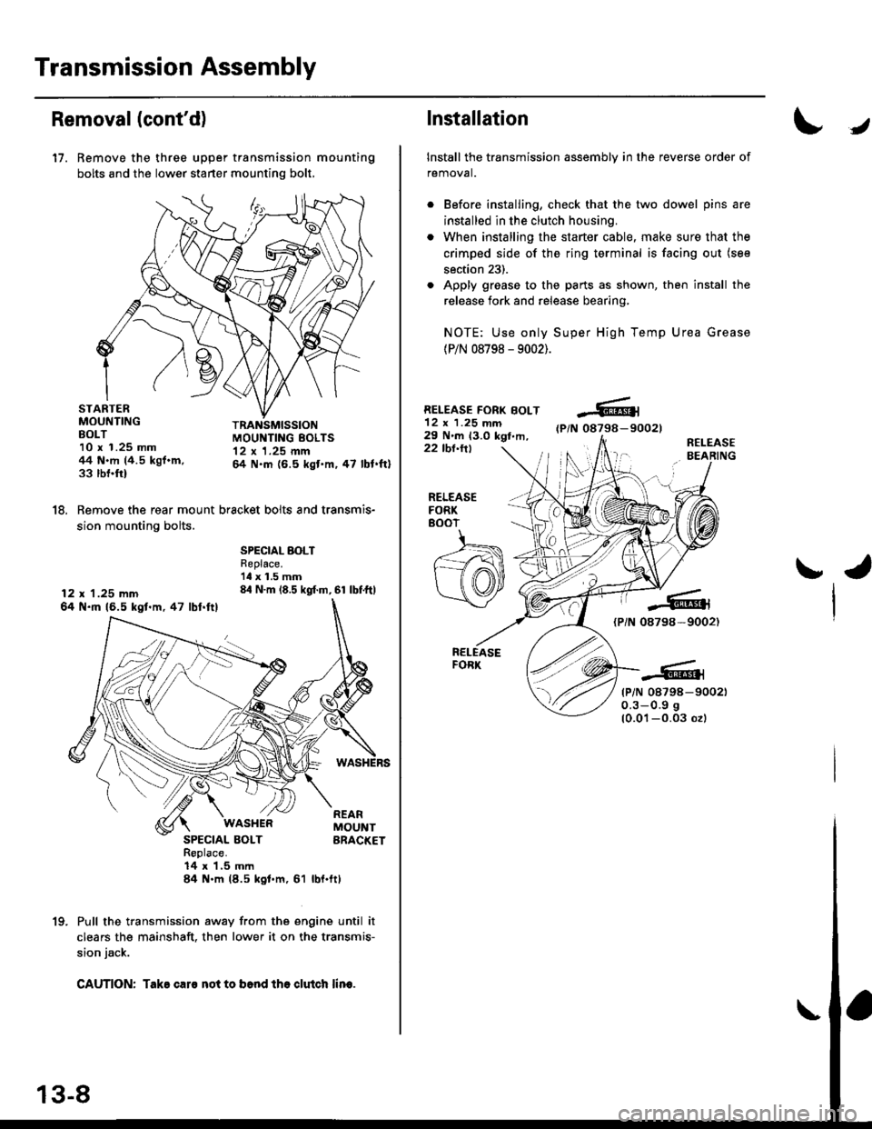
17. Remove the three upper transmission mounting
bolts and the lower starter mounting bolt,
STARTERMOUNTINGBOLT10 x 1.25 mm44 N.m (4.5 kgf.m,33 rbnftl
TRANSMISSIONMOUI{TING EOLTS12 x 1.25 mm& N.m (6.5 kgt'm,47 lbl.ftl
18. Remove the rear mount bracket bolts and transmis-
sion mounting bolts.
12 x 1.25 mm64 N.ft 16.5 kgl.m,47 lbl.ftl
SPECIAL BOLTReplace.'ll x 1.5 mm84 N.m (8.5 kgf.m, 61 lbf.ftl
SPECIAL BOLTReplace.14 x 1,5 mln84 N.m (8.5 kgl.m, 61
WASI{ERREARMOUNTBRACKET
rbl.ftt
Pull the transmission away from the engine until it
clears the mainshaft. then lower it on the transmis-
sion jack.
CAUTION: Take caro not to b6nd tho clutch lin€.
1(|
Installation
Install the transmission assembly in the reverse order of
removal.
Before installing, check that the two dowel pins are
installed in the clutch housing.
When installing the starter cable, make sure that the
crimped side of the ring terminal is facing out (see
section 23).
Apply grease to the parts as shown, then install the
release fork and release bearing,
NOTE: Use only Super High Temp Urea Grease
(P/N 08798 - 9002).
RELEASE FORK BOLT12 x 1.25 mm29 N'm 13.0 kgt,m,(P/N 08798-90021
22 tbl.ttlR€LEASEBEARING
J
RELEASEFORK8()07
ra
{PiN 08798-9002)
tP/N 08798-900210.3-0.9 g
10.01-0.03 ozl
Page 589 of 2189

. Torque the mounting bolt and nuts in the sequence
shown.
O 12 x 1.25 mm64 N.m {6.5 kgt.m,47 lbf.fr)
@ 12 x 1.25 mm74 N.m (7.5 kgl'm,54 tbt.fr)
Check that the bushings are not twisted or offset.
Install the clip as shown.
SHIFT ROD
Turn the boot so the hole is facing down.
Make sure the boot is installed on the shift rod.
O) 12 x 'l.25 mm64 N.m 16.5 kgl.m,47 tbt.ft)
I
a
a
a
a
8 x 1.25 mmN.m t2.2 kgt.m, l6 lbl'tt)
6 x 1.0 mm9.8 N.m (1.0 kgl.m.7.2 tbf.tr)
. Apply grease to the slave cylinder push rod.
NOTE: Use only Super High Temp Urea Grease
{P/N 08798 - 9002}.
CLUTCHUNE
a
a
(P/N-6tl
08798-9002)
8 x 1.25 mm22 N.m 12.2 kgl.n.16 tbf.frl
. Turn the breather cap so that the "F" mark points at
the front of the car as shown.
Refill the transmission with the recommended oil
(see page 13-3).
Connect the positive (+) cable first, then the negative
(-) cable to the battery.
Check the clutch oDeration,
Shift the transmission and check for smooth opera-
tion.
Check the front wheel alignment (see section 18).
FRONT
13-9
Page 618 of 2189

Mainshaft Thrust ShimI
I
Adjustment (cont'dl
b.Attach the mainshaft holder to the mainshaft asfollows:
NOTEI
. Back-out the mainshaft holder bolt and loosen
the two hex bolts.
. Fit the holder over the mainshaft so its lip istoward the transmission.
. Align the mainshaft holder's lip around thegroove at the inside of the mainshaft splines,then tighten the hex bolts.
MAINSHAFT HOLOERBOLT
MAINSIIAFTHOLDER07GAJ-PG20110
d.
Seat the mainshaft fully by tapping on the end witha plastic hammer.
Thread the mainshaft holder bolt in until it just
contacts the wide surface of the mainshaft base.
u
e. Zero a dial gauge on the end ofthe mainshaft.
MAINSHAFT HOLDER07cAJ_PG20110
Turn the mainshaft holder bolt clockwise: stop turn,ing when the dial gange has reached its maximummovement. The reading on the dial gauge is theamount of mainshaft end olav.
CAUTION: Turning the mainshaft holder bolt morethan 60 degre€s after the needle ot the dial gauge
stops moving may damage the iransmission.
lf the reading is within the standard. the clearance iscorrecl.
lf the reading is not within the standard, recheck theshim thickness.
Standard: 0.11 - 0.18 mm {0.00it - 0.007 in}
t.
\,J