1999 HONDA CIVIC Valves
[x] Cancel search: ValvesPage 187 of 2189

Valves, Valve Springs and Valve Seals
Removal
NOTE: ldentify valves and valve springs as they are
removed so that each item can be reinstalled in its origi-
nal Dosition.
l. Using an appropriate-sized socket and plastic mal-
let, lightly tap the valve retainer to loosen the valve
keeoers.
PLASTIC
Install the valve spring compressor. Compress the
spring and remove the vSlve keepers.
VALVE SPRINGCOMPRESSORATTACHMENT07757 - PJ1010A
VALVE SPRINGCOMPRESSOR ATTACHMENTEXTENSIONOTMAF - PRgOIOA
I
Sn.p-on CFr1lCOMPRESSOR
6-77
3. Installthe valve guide seal remover.
VALVE GUIDE SEAL REMOVERCOMMERCIALLY AVAILABLELtst-E P/N 571100 ()R KD3350
4. Remove the valve guide seal.
Valve Dimensions
lntake Valvo
A Standsrd {Newl; 32.90 - 33.10 mm (1.295 - 1.303 in}
B St ndard {New}: 101.00 - 101.30 mm (3.976 - 3'988 in}
C Stsndard (Nowl: 5./t5 - 5.,185 mm (0.2156 - 0.2159 in)
C Servico Limit 5.445 {0.21/l| in)
D Siandard (N!w): 1.05 - 1.35 mm (0.041 - O.05il inl
D S€.vice Limit: 0.85 mm {0.033 inl
Exhaust Valve
A Standard lNewli 27.90 - 28.10 mm (1.098 - 1.106 in)
B Stlndard {Nowl: 100.m - 1qr,90 mm {3.961 - 3.972 in)
C Stsndard {Now}: 5.450 - 5.,[60 mm {0.21,16 - 0.2150 in)
C Service Limit 5.420 10.213,0 inl
D Standard {New): 1.65 - 1.95 mm (0.065 - 0.077 in)
D Sorvico Limit: l.ils mm 10.057 inl
Page 188 of 2189

Valve Seats
Reconditioning
1. Renew the valve seats in the cylinder
valve seat cutter.
NOTE: lf any guides are worn (see
replace them (see page 6-80) before
valve seats,
head with a
page 6-79),
cutting the
Carefully cut a 45o seat, removing only enough mate-
rial to ensure a smooth and concentric seat.
Bevel the upper edge of the seat with the 30" cutterand the lower edge of the seat with the 60. cutter.Check width of seat and adjust accordingly,
Make one more very light pass with the 45" cutter toremove any possible burrs caused bv the other cut-
ters.
Valve Seat Width:
Standard (Newl: 1.25 - 1.55 mm {0.0't9 - 0.061 in)Service Limii: 2.0 mm 10,08 inl
Sear Widrh
6-78
5. After resufacing the seat. inspect for even valveseating: Apply Prussian Blue Compound to thevalve face, and insert the valve in its original loca-tion in the head. then lift it and snap it closedagainst the seat several times.
PRUSSIAN BLUE COMPOUND
The actual valve seating surface, as shown by theblue compound, should be centered on the seat.. lf it is too high (closer to the valve stem), you mustmake a second cut with the 60. cutter to move itdown, then one more cut with the 45. cutter torestore seat width.
. lf it is too low (closer to the valve edge), you must
make a second cut with the 30. cutter to move itup. then one more cut with the 45. cutter to restoreseat width.
NOTE: The final cut should always be made withthe 45" cutter,
7. Insen the intake and exhaust valves in the head and
measure valve stem installed heioht.
Intaka Valve Stem Installed Height:
Standsrd lNaw): 37.465 - 37.935 mm(1./P50 - r.4935 inl
Sorvice Limit: 38.185 mm 0.5033 in)
Exhau3t Valv€ Stem Installed Height:
Standard (New): 37.165 - 37.6i|5 mm(1.46:t2 - 1.i1817 inl
Servico Limit 37.885 (1.4915 inl
lf valve stem installed height is over the service limit,replace the valve and recheck. lf it is still over the ser-vice limit, replace the cylinder head; the valve seat inthe h6ad is too deep.
(
Page 192 of 2189

Valves
1.
Installation
Coat the valve stems with oil. lnsert the valves into
the valve guides.
NOTE: Check that the valves move up and downsmoothly.
Installthe spring seats on the cylinder head.
Install the valve seals using the special tool.
NOTE: Exhaust and intake valve seals are not inter-
changeable.
WHITESPRING
VALVE GUIDE SEAL INSTALLERKD-28)g (Commercially available)NOTE: Use small lDend of tool,
2.
BRACKSPRING
VALVE SEALReplace.
tNsTALLERVALVE GUIDE SEALKD-2899NOTE: Use small lDend of tool
(
4. lnstall the valve spring and valve retainer, theninstall the valve spring compressor. Compress thespring, and install the valve keepers.
NOTE: Place the end of the valve spring with closely
wound coils toward the cylinder head.
VALVE SpRtNG VALVE SPRTNG
COMpRESSOR COMPRESSORATTACHMENT
ATTACHMENT EXTENSTON
0775? _ pJlOl0A o?MAF - PR9010A
VALVE SPRING COMPRESSORlCommercially available)Snap-on CF711 or KD-3tXlwith #32JAWSLightly tap the end of each valve stem two or threetimes with the wooden handle of a hammer to ensureproper seating of the valve and valve keepers.
NOTE: Tap the valve stem only along its axis soyou do not bend the stem.
I
5.
Page 435 of 2189

PGM-FI System
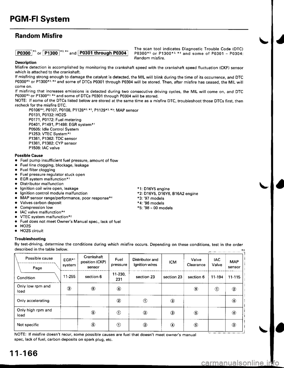
Random Misfire
lFoioo l*u o, [FTioo l*' *' and
The scan tool indicates Diagnostic Trouble Code (DTC)
P0300*5 or P1300*3 *1 and some of P0301 - P0304:Random misfire.Description
Misfire detection is accomplished by monitoring the crankshaft speed with the crankshaft speed fluctuation (CKF) sensorwhich is attached to the crankshaft.
lf misfiring strong enough to damage the catalyst is detected. the MIL will blink during the time of its occurrence, and DTCP0300*5 or P1300*3'*' and some of DTCs P0301 through P0304 will be stored. Then, after misfire has ceased, the MIL willcome on.
lf misfiring that increases emissions is detected during two consecutive driving cycles, the MIL will come on, and DTCP0300*5 or P1300*3 *a and some of DTCS P0301 through P0304 will be stored.NOTE: lf some of the DTCS listed below are stored at the same time as a misfire DTC. troubleshoot those DTCS first, thenrecheck for the misfire DTC.
P0106*4. P0107. P0108, P1128*3 *5, Pl129*3 *5; MAP sensorP0131. P0132: HO2S
P0171, P0112i Fuel metering
P0401, P 1491, P1498: EGR svstem*1P0505: ldle Control SystemP1253: VTEC System*,P1361, P1362: TDC sensorP1381, Pl382: CYP sensorP1508: IAC valve
Possible Cause. Fuel pump insufficient fuel pressure, amount of flow. Fuel line clogging, blockage, leakage. Fuel filter clogging. Fuel pressure regulator stuck open. EGR system malfunction*1. Distributormalfunction. lgnition coil wire open. leakage *l: D16Y5 engine. lgnition control module malfunction *2: D16Y5, D16Y8, Bt6A2 engine. MAP sensor range/performance, poor response*r *3: '97 models. Valves carbon deposit *4;'96 models. Compression low *5: '98 - 00 models. IAC valve malfunctionr.. VTEC system malfunction*,. Fuel does not meet Owner's Manual spec., lackoffuel. HO2S. HO2S circuit
Troubleshooting
By test-driving, determine the conditions during which misfire occurs, Depending on these conditions, test in the orderdescribed in the table below.
Possible
- --^ ---
rage
causeEGR*1
system
Crankshaft
position (CKP)
sensor
Fuel
pressure
Distributor and
lgnition wirestcMClearance
tAc
ValveMAP
sensor
section 611-230,
231section 23section 23section 611-19411
Only low rpm and
loado@@oo
Only accelerating@o@@
Only high rpm and
toaooo@
Not specificoo@
NOTE: lf misfire doesn't recur, some possible causes are fuel that doesn't meet owne/s manualspec, lack of fuel, carbon deposits on spark plug, etc.
1 1-1 66
I
P0304
Page 467 of 2189

ldle Control System
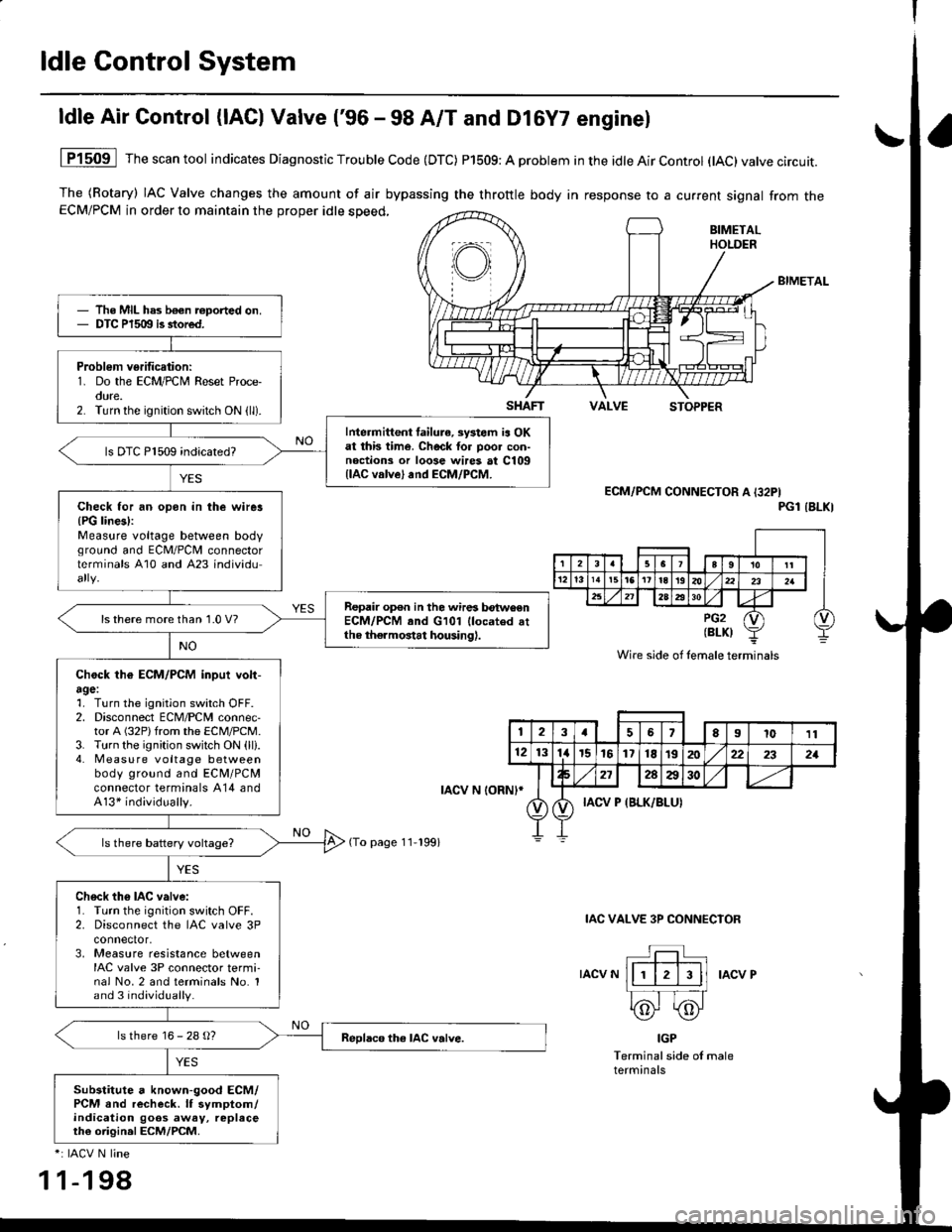
ldle Air Control (lAC) Valve ('96 - 98 A/T and Dl6Y7 enginel
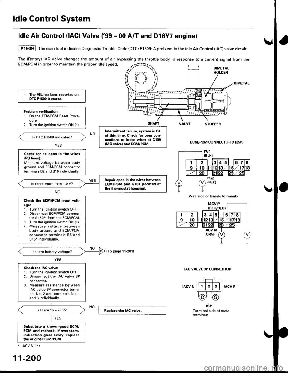
The (Rotary) IAC Valve changes the amount of air bypassing the throttle body in response to a current signal from theECM/PCM in order to maintain the proper idle speed,
BIMETAL
VALVESTOPPER
1P1509 Thescantool indicates Diagnostic Trouble Code (DTC) P1509: A problem in the idle Air Control (tAC)valve circuit.
ECM/PCM CONNECTOR A I32PIPGl IBLKI
IAC VALVE 3P CONNECIOR
IACV NIACV P
IGP
Terminal side of maleterminals
*: IACV N line
1 1-198
The MIL has b€€n roported on.DTC P1509 is stored.
Problem verification:1. Do the ECM/PCM Reset Proce-oure.2. Turn the ignition switch ON (ll).
Intermittent failura, systom ia OKat this time. Check tor poo. con-noctions or loose wires at C109llAC valve) and ECM/PCM.
ls DTC P1509 indicated?
Check for an opon in the wirer{PG lines):Measure voltage between bodvground and ECM/PCII connectorterminals A10 and A23 individu
Repair op€n in the wires betwoenECM/PCM and G101 llocated attho thermostat housing).
ls there more than 1.0 V?
Chock th€ ECM/PCM inpui volt-agel1. Turn the ignition switch OFF.2. Disconnect ECM/PCM connec-tor A (32P)from the ECM/PCM.3. Turn the ignition switch ON (ll).4. Measu re voltage betweenbody ground and ECM/PCMconnector terminals A14 andA13* individually.
Ch6ck th6 IAC valve:1. Turn the ignition switch OFF.2. Disconnect the IAC valve 3Pconnector,3, Measure resistance betweenIAC valve 3P connector termi-nal No.2 and terminals No. 1and 3 individually.
ls there 16 - 28 g?
Substitute a known-good ECM/PCM and recheck. lf symptom/indication goos away, replaceth€ origin.l ECM/PCM.
SHAFT
rAcv N loRNl*
(To page 11-199)
Wire side of lemale terminals
123a56El011
121314r5161718t9202:22321
272AA30
IACV P {BLK/BLUI
Page 469 of 2189

ldle Gontrol System
The (Rotary) IAC Valve changes the amount of air bypassing the throttle body in response to a current signal from the
ECM/PCM in order to maintain the proper idle speed.BIMETALHOLDER
BIMETAL
SHAFTVALVESTOPPER
ECM/PCM CONNECTOR B {25P}
(To page 11-201)
IAC VALVE 3P CONNECTOR
IACV NIACV P
ldle Air Control {lACl Valve ('99 - 00 A/T and Dl6Y7 enginel
YES
1P1509 lThescantool indicates Diagnostic Trouble Code (DTC) P1509:A problem inthe idleAirControl (lAC)valve circuit.
IGP
Terminal side of maleterminals
Sub3titute e known-good ECM/PCM .nd recheck. lf 3vmptom/indicalion goos away, replac6thc original ECM/PCM.
*: IACV N line
11-200
Tho MIL has b€en reported on.OTC P1509 is sto.ed.
Problem verilicationr1. Do the ECM/PCM Reset Proce-dure.2. Turn the ignition switch ON (ll).
Intermittont tailure, sy3tem i3 OKat thb time. Check for poor con'noctions or loose wiros at C109(lAC velvel and ECM/PCM.
ls DTC P1509 indicated?
Check for an oDen in the wilosIPG linesl:Measure voltage between bodyground and ECM/PCM connectorterminals 82 and 810 individually.
Ropail open in the wires be'tw€enECM/PCM .nd G101 llocated .tthe the.mostat housingl.ls there more than 1.0 V?
Check tho ECM/PCM input volt-age:1. Turn the ignition switch OFF.2. Disconnect ECM/PCM connec-tor A (32P)trom the ECM/PCM.3. Turn the ignition switch ON (ll).
4, Measure voltage betweenbody ground and ECM/PCMconnector terminals 86 and815* individually.
Chock the IAC v.lve:1. Turn the ignition sw;tch OFF.2. Disconnect the IAC valve 3Pconnoctor.3. Measure resistance betweenIAC valve 3P connector termi'nal No. 2 and terminals No. 1and 3 individually.
ls there 16 - 28 O?
Wire side of female terminals
Page 681 of 2189

Description
The automatic transmission is a 3-element torque converter and a dual-shaft electronically controlled unit which provides
4 soeeds forward and 1 reverse.
Torque Convertel, Geats, and Clutches
The torque converter consists of a pump, turbine and stator, assembled in a single unit. They are connected to the engine
crankshaft so they turn together as a unit as the engine turns. Around the outside of the torque converter is a ring gear
which meshes with the starter pinion when the engine is being started. The entire torque converter assembly seryes as a
flywheel while transmiuing power to the transmission mainshaft.
The transmission has two parallel shafts: the mainshaft and the countershaft. The mainshaft is in Iine with the engine
crankshaft. The mainshaft includes the 1st, 2nd and 4th clutches, gears tor 2nd, 4th, reverse and lst (3rd gear is integral
with the mainshaft, while the reverse gear is integral with the 4th gear). The countershaft includes the 3rd clutch, and
gears for 3rd,2nd, 4th, reverse. 1st and park. The gears on the mainshaft are in constant mesh with those on the counter-
shaft. When certain combinations of gears in transmission are engaged by clutches. power is transmitted from the main-
shaft to the countershaft to provide E, ld, E, and E positions.
Electronic Control
The electronic control svstem consists of the Powertrain Control Module {PCM), sensors, a linear solenoid and four
solenojd valves. Shifting and lock-up are electronically controlled for comtonable driving under all conditions. The PCM is
located below the dashboard, under the front lower panel on the passenger's side
Hydraulic Control
The valve bodies include the main vatve body, the secondary valve body, the regulator valve body, the servo body and the
lock-up valve body through the respective separator plates, They are bolted on the torque converter housang
The main valve body contains the manual valve, the 1-2 shift valve. the 2nd orifice control valve, the CPB {Clutch Pressure
Back-up) valve, the modulator valve. the servo control valve, the relief valve, and ATF pump gears The secondary valve
body contains the 2-3 shift valve. the 3-4 shift valve, the 3-4 orifice control valve, the 4th exhaust valve and the CPC (Clutch
pressure Control) valve. The regulator valve body contains the pressure regulator valve, the torque converter check valve,
the cooler relief valve, and the lock-up control valve. The servo body contains the servo valve which is integrated with the
reverse shift fork, and the accumulators. The lock-up valve body contains the lock-up shift valve and the lock-up timing
valve. The linear solenoid and the shift control solenoid valve Ay'B are bolted on the outside of the transmission housing,
and the lock-up control solenoid valve Ay'B is bolted on the outside of the torque converter housing. Fluid from regulator
passes through the manual valve to the various control valves. The clutches receive fluid from their respective teed pipes
or internal hydraulic circuit.
Shift Control Mechanism
Input from various sensors located throughout the car determines which shift control solenoid valve the PCM will activate
Activating a shift control solenoid valve changes modulator pressure, causing a shift valve to move. This pressurizes a line
to one of the clutches, engaging that clutch and its corresponding gear, The shift control solenoid valves A and B are con-
trolled by the PCM.
Lock-up Mechanism
In ,Dt1 position, in 3rd and 4th. and in E position in 3rd, pressurized fluid is drained from the back of the torque converter
through a fluid passage, causing the lock-up piston to be held against the torque converter cover. As this takes place, the
mainshaft rotates at the same as the engine crankshaft. Together with hydraulic control, the PCM optimizes the timing of
the lock-up mechanism. The lock-up valves control the range of lock-up according to lock-up control solenoid valves A and
B, and linear solenoid. When lock-up control solenoid valves A and B activate, the modulator pressure changes The lock-
up control solenoid valves A and B and the linear solenoid are controlled by the PCM.
(cont'd)
14-3
Page 691 of 2189

Electronic Control SYstem
The electronac controt system consrsts of a Powertrain control Module (PcM), sensors, a Iinear solenoid and four solenoid
valves, shifting and lock-up are electronically controlled for comfortable driving under all conditions The PCM is located
below the dashboard, under the front lower panel on the passenger's side
PGM-FIControl Sy3tem
A/T Control SYstom
Shift Control
Lock-uD Control
14-13