Page 152 of 2189

Valve Guides
7.
VALVESEAT
PFUSSIAN BTUE COMPOUNO
The actual valve seating surface. as shown by the
blue comDound, should be centered on the seat.
. lf it is too high (closer to the valve stem), you
must make a second cut with the 60'cutter to
move it down, then one more cut with the 45'
cutter to restore seat width,
. lf it is too low (closer to the vslve edge), you
must make a second cut with the 30" cutter to
move it uD, then one more cut with the 45'cutter
to restore seat width.
NOTE: The final cut should always be made with
the 45" cutter.
lnsert the intake and exhaust valves in the head and
measure the valve stem installed height.
Intake. Exhau3t Siem Installsd Height:
Standard (New): 53.17 - 53.6,4 mm
12.093 - 2.112 in)
Sorvice Limit: 53.89 mm (2.122 in)
lf the valve stem installed height is over the service
limit. reDlace the valve and recheck. lf its still over
the service limit, replace the cylinder head; the
valve seat in the head is too deep.
VALVE STEMINSTALLED HEIGHT
8.
\-
Replacement
1.As illustrated below, use a commercially-available
air-impact valve guide driver attachment modified
to fit the diameter of the valve guides. In most cases.
the same procedure can be done using the special
tool and a conventional hammer.
VALVE GUIDE DRIVERlCommerciallv available)5.3 mm
87 mm +- 57 mft
t3.43 in) | 12 24 inl
tr-r'10.8 mm(0.42 inl
or
VALVE GUIDE DRIVER, 5.5 mm
07742 - 0010100
Select the proper replacement guides. and chill them
in the freezer section of a refrigerator for about an
nour.
Use a hot plate or oven to evenly heat the cylinder
head to 300"F (150'C). Monitor the temperature with
a cooking thermometer.
CAUTION:
. Do not use a torch; it may warp the head.
Do not got the head hottel than 300"F (150"C1;
excessive heat may loosen thg valve seats.
To avoid burns. use heayy gloves whon handling
the heated cylinder h€ad.
{cont'd)
6-41
Page 154 of 2189

Valves
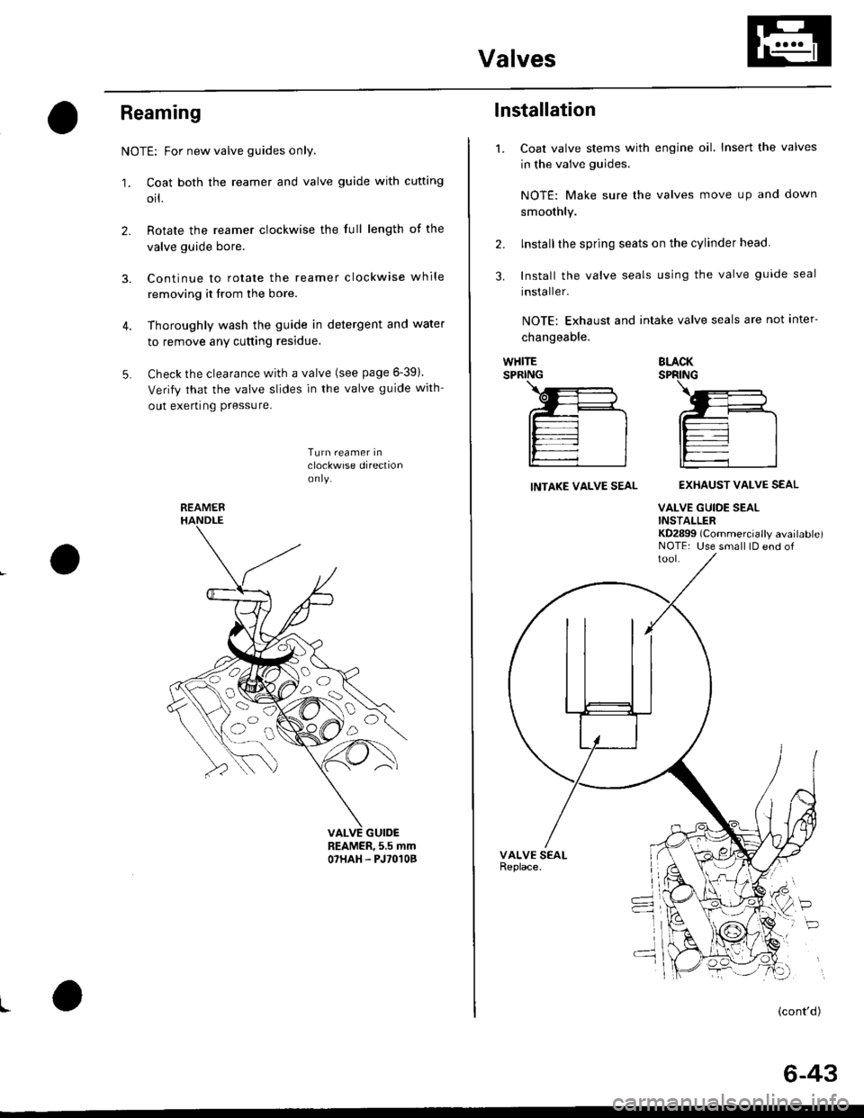
Reaming
NOTE: For new valve guides only.
1. Coat both the reamer and valve guide with cufting
orl.
2. Rotate the reamer clockwise the full length of the
valve guide bore.
3. Continue to rotate the reamer clockwise while
removing it from the bore.
4. Thoroughly wash the guide in detergent and water
to remove any cutting residue.
5. Check the clearance with a valve (see page 6-391.
Verify that the valve slides in the valve guide with-
out exerting Pressure.
Turn reamer inclockwise direclionon ly.
REAMER, 5.5 mmO7HAH. PJ'O'IOB
I
REAMER
oa)o,
o
o
1.
lnstallation
Coat valve stems with engine oil. Insert the valves
in the valve guides.
NOTE: Make sure lhe valves move up and clown
smoothly.
lnstallthe spring seats on the cylinder head.
Install the valve seals using the valve guide seal
installer.
NOTE: Exhaust and intake valve seals are not inter-
changeable.
2.
3.
WHITESPRINGBLACKSPRING
INTAKE VALVE SEALEXHAUST VALVE SEAL
VALVE GUIDE SEALINSTALLERKD2899 (Commercially available)NOTE: Use small lD end of
P
(cont'd)
6-43
Page 155 of 2189

Valves
Camshaft/Rocker Arms and
Camshaft Seal/Pulley
Installation (cont'd)
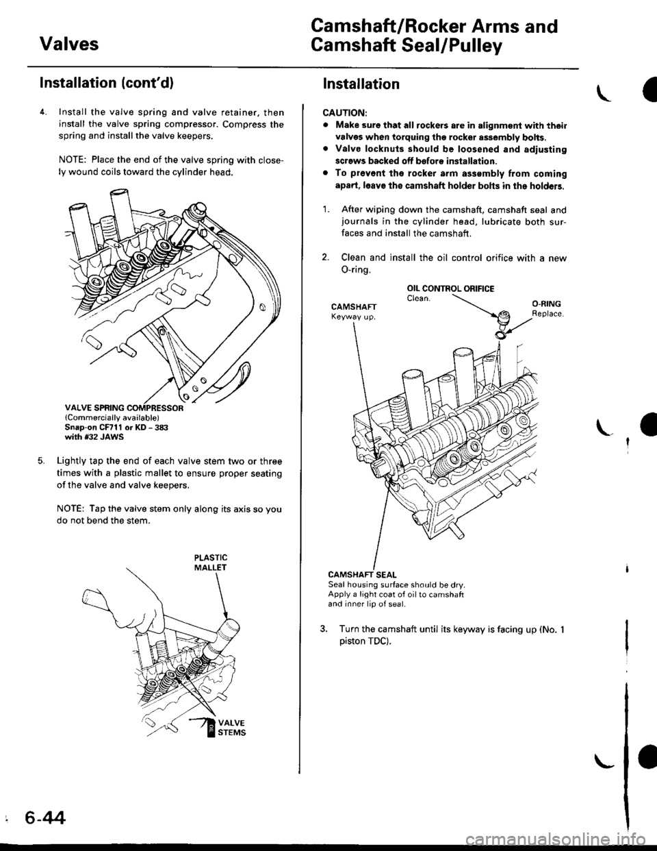
4. Install the valve spring and valve retainer. then
install the valve spring compressor. Compress the
spring and installthe valve keepers.
NOTE: Place the end of the valve spring with close-
ly wound coils toward the cylinder head.
lCornmercially available)Snap-on CFrll or KD - 3tX'with #32 JAWS
Lightly tap the end of each valve stem two or three
times with a plastic mallet to ensure proper seating
of the valve and valve keepers.
NOTE: Tap the valve stem only along its axis so you
do not bend the stem.
' 6-44
Installation
CAUTION:
. Make sure that all tockers are in alignment with their
valvgs when torquing the rocket assembly bolts,. Valve locknuls should be loosened and adiusting
screws backed off bofore installation.
. To prevont tho rocker arm a$smbly from coming
apad, l6av€ the camshaft holder bohs in the holdeB.
1. After wiping down the camshaft, camshaft seal andjournals in the cylinder head, lubricate both sur-
faces and install the camshaft.
2. Clean and install the oil control orifice with a new
O-ring.
CAMSHAFT SEALSeal housing surface should be dry.Apply a light coat of oil to camshaftand inner lip of seal.
3. Turn the camshaft until its keyway is facing up (No.
piston TDC).
OIL CONTROL ORIFICE
Page 156 of 2189

Cylinder Head
4. Apply liquid gasket (Part No. 08718 - 0001 or 08718 -
0003) to the head mating surfaces of the No. 1 and
No.5 camshaft holders.- Apply liquid gasket to the shaded areas
Set the rocker arm assemblY in place and loosely
installthe bolts.- Make sure that the rocker arms are properly posi-
tioned on the valve stems.
Tighten each bolt two turns at a time in the sequence
shown below to ensure that the rockers do not bind
on the valves.
Specitied torquo:
8 mm bolts: 20 N.m (2.0 kgt'm, l/t lbf'ft)
Apply engine oil to the threads.
6 mm bolts: 12 N.m {1.2 kgif'm, 8.7 lbf'ft)
Apply engine oil to the thresds.
6 mm bolts: O, @. @, @
7. Install the back cover. then install the camshaft pul-!
6-45
lnstallation
lnstallthe cylinder head in the reverse order of removal:
NOTE:
. Always use a new head gasket.
. Cylinder head and cylinder block surface must be
clean.
. "UP" mark on the camshaft pulley should be at the top
. Turn the crankshaft so the No. 1 piston is at TDC (see
page 6-20).
. Clean the oil control orifice before installing.
a Do not use the upper cover and lower cover to store
removeo rlems.
Clean the upper cover and lower cover before instal-
taUon.
Cylinder head dowel pins must be aligned.1.
CYUNOER HEAD
PINS
(cont'd)
Page 159 of 2189
Gylinder Head/Valve Train
816A2 engine
Special Tools ............. 6'50 Rocker Arms
VTEC Contlol System
Troubfeshooting Flowchart ............ 6-51 Disassembly/Reassembly ...............6'72
VTEC Solenoid ValveRocker Arms and Lost Motion Assemblies
Inspection ...""'...... 5-54 Inspection .........""' 6-73
VTEC Rocker ArmsRocker Arms and Shafts
Manual Inspection ........................... 6-54 Clearance Inspection ..'..."'.............. 6-74
Inspection Using Special Tools .....' 6-55 Camshafts
Valve Clearance
.^ Adiustment .........." 6-57 Valves'Valve Springs and Valve Seals
. t Crankshaft Pulley and Pulley Bolt Removal """"""""' 6-77
Replacement ..".....6-59 Valve Seats
Timing BeltReconditioning ......6'78
Cylinder Headlnstallation '............ 6-82
Page 167 of 2189

Valve Glearance
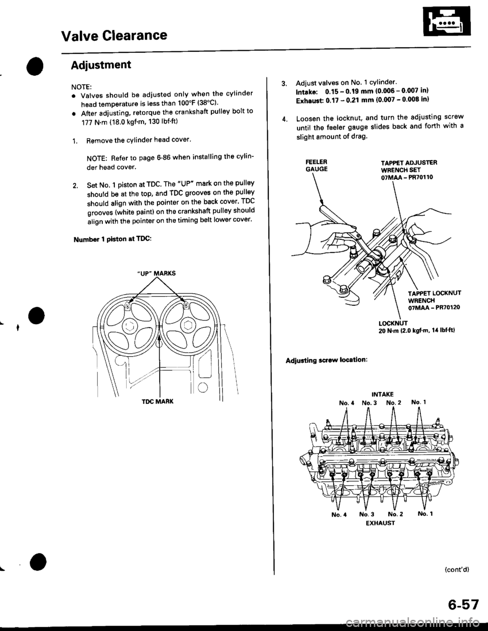
Adjustment
NOTE:
. Valves should be adjusted only when the cylinder
head temperaturs is less than 100'F (38'C)'
. After adjusting, retorque the crankshaft pulley bolt to
177 N.m (18.0 kgf'm, 130 lbt'ft)
1. Remove the cylinder head cover'
NOTE: Refer to page G86 when installing the cylin-
der head cover.
2. Set No. 1 pi$on at TDC. The "UP" mark on the pullsy
should be at the top, and TDC grooves on the pulley
should align with the pointer on the back cover' TDC
grooves {white paint) on the crankshaft pulley should
align with the pointer on the timing belt lower cover'
Number I Piston at TDC:
4.
Adjust valves on No. 1 cylinder.
lntako: 0.15 - 0.19 mm {0'006 - 0.007 in)
ExhaGt 0.17 - 0.21 mm {0'007 - 0 008 inl
Loosen the locknut, and turn the adjusting screw
until the feeler gauge slides back and forth with a
slight amount of drag.
TAPPET ADJUSTERWFENCH SET07MM - PR70110
TAPPET LOCKNUTWRENCH07MAA - PR70120
Adiusting sclaw location:
LOCKNUT20 N.m {2.0 kgf'm, lil lbt'ftl
(cont'd)
6-57
Page 168 of 2189
Valve Clearance
I
I
I
Adjustment {cont'd)
5. Tighten the locknut and recheck clearance.Repeat adjustment if necessary.
Rotate the crankshaft 180. counterclockwise(camshaft pulley turns 90'). The "Up" mark shouldbe on the exhaust side. Adjust valves on No. 3 cylin-der.
Number 3 piston at TDC:
FE€LER GAUGE
"UP- MARKS
6-58
7. Rotate the crankshaft '180. counterclockwise tobring No. 4 piston to TDC. The ,,Up,. mark shouldbe pointing straight down. Adjust valves on No. 4cylinder.
Number 4 piston at TDC:
8, Rotate the crankshaft 180. counterclockwise tobring No. 2 piston to TDC. The "Up., marks shouldbe on the intake side. Adjust valves on No. 2 cylin_der.
Number 2 piston at TDC:
L
Page 176 of 2189
Cylinder Head
lllustrated Index (cont'dl
CYLINDER HEADBOLTS11 x 1.5 mm83 N.m {8.5 kg{.m, 61Apply engine oilto threads.
INTAKE VALVE SPRING INNER
VALVE KEEPERS
SPRING RETAINER
INTAKE VAI.VE SPRING OUTER
valvEKEEPEBS\:""j"*'
SPRING RETAINER
EXHAUST VALVESPRING
VALVE SEALReplace.
VALVE
LOST MOTIONASSEMBLY
EXHAUST VAL
VALVE SEALReplace.
SPRING SEAT
VALVE GUIDE
INTAKE VALVE
ROCKER SHAFT
SEALING AOLTS.20 mm64 N.m (6.5 kgt.m, 47 tbf.ft)
t
il
HEAO OIL CONTROLORIFICEClea n.
a
6-66