Page 1572 of 2189
lgnition System
Component Location Index
IGNITION TIMING CONTROL SYSTEM
. Troubleshooting, section 11
. ldle speed Inspection/Adjustment. section 11
. Inspection and Setting, page 23-105
SERVICE CHECK CONNECTOR {2P}Iwiie colors: 8RN and BLKI
TEST TACI{OMETER CONNECTOB
IGNITION WIRESlnspection and Test, page 23-110
PLUGSInspection, page 23 1 11
Replacement, page 23'106Overhaul, page 23-107lgnition Coil Test, page 23'110lgnition Control Module llCM)Input Test, page 23-109
23-102
Page 1573 of 2189
lgnition System
-Circuit Diagram: '96 - 97 models
.i-
8LU
I
nBLU BLU I
tl
lnI TESTI TACHOMETEF\-7 CONNECTOR
TACHOMETERTCM (CW)
J-) {sh,eldinsr't I
tfYEL BBN/BLK
+l
I:
G101
$t+++
UNDER HOOD FUSE/ RELAY 8OX
BLh TEL YEL GBN
BLKlYEL
IAl
BLK/YEL YELIGFN
IGN]TIONCOL
TDCrTop dead cenlerCKP: Crankshall postionCYP Cylnder poslon
TDC]CKP]CYP SENSoR
" *]BLU'*2 WHI BLU
IGNITION CONIROLMODULE (CM)
/ Has b'r ll n\I iorse I
rUSE FE-AV BO}
*u r-. .-*---{<9ot # u,,."r. | |
\j/ El v
tl
23-103
Page 1574 of 2189
lgnition System
Circuit Diagram :'98-00 models
UNDER HOOD FUSUFELAY BOX'x'E;;;;-;;;;l /; l-*;- Ecw.cM
ffiwFnBLK<-wHr\9-
Y
tlBTKTYEL YEUGRN
IGN]TIONswtTcHUNDER,DASHFUSE/BELAY BOX
YEt
J
BLK
J
FED
+
*1 :H TACHI*2 :TEC
9 *IBLU'
23-104
Page 1576 of 2189

lgnition System
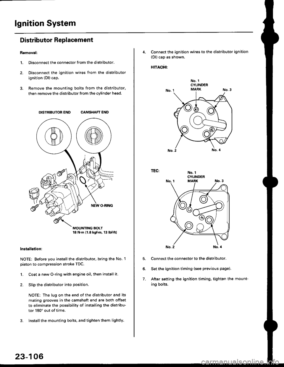
Distributor Replacement
Removal:
1. Disconnect the connector from the distributor.
2. Disconnect the ignition wires from the distributor
ignition {Dl) cap.
3. Remove the mounting bolts from the distributor,
then remove the distributor from the cylinder head.
DISTRIBUTOR END CAMSHAFT END
MOUNTING BOLT18 N.m 11.8 kgtm, 13lbf.ltl
lnstallation:
NOTE: Before you install the distributor. bring the No. 1
piston to compression stroke TDC.
1. Coat a new O-ring with engine oil, then install it.
2. Slip the distributor into position
NOTE: The lug on the end of the distributor and its
mating grooves in the camshaft end are both offset
to eliminate the possibility of installing the distribu-
tor 180" out of time.
3. Installthe mounting bolts, and tighten them lightly.
23-106
4, Connect the ignition wires to the distributor ignition
(Dl) cap as shown.
rracfit'
No. 1CYLINDERMARK
No. 1CYLINDER
TEG:
5.
6.
7.
No. 2No. a
Connect the connector to the distributor.
Set the ignition timing (see previous page).
After setting the ignition timing, tighten the mount-
ing bolts.
Page 1578 of 2189
lgnition System
Distributor Overhaul (cont'dl
TEC:
IGNITION CONTROLMODULE IICM'Input Test, page 23-1
DISTRIBUTOR IGNITION {DI} HOUSINGCheck for cracks and damage.
COVER
DISTRIBUTOR IGNITION IDI) ROTOB
CAP SEALCheck for damage.DISTRIBUTOR IGNITION {DII CAPCheck for cracks, wear,damage, and fouling.Clean or replace,
IGNITION COILTest, page 23-110
O-RINGReplace
\
I
@
TDC/CKP/CYP S€NSORTroubleshooting, section 1 1Do not disassemble.
WHT/BLU
23-104
Page 1579 of 2189

Jlgnition Control Module (lCMl Input Test
NOTE:
. See section 1'l when the malfunction indicator lamp
(MlL) turned on.
. Perform an input test for the ignition control module
(lCM) after finishing the fundamental tests for the
ignition system and the fuel and emissions systems
1. Remove the distributor ignition (Dl) cap, the distrib-
utor ignition (Dl) rotor and the leak cover (TEC).
2. Disconnect the wires from the lCM.
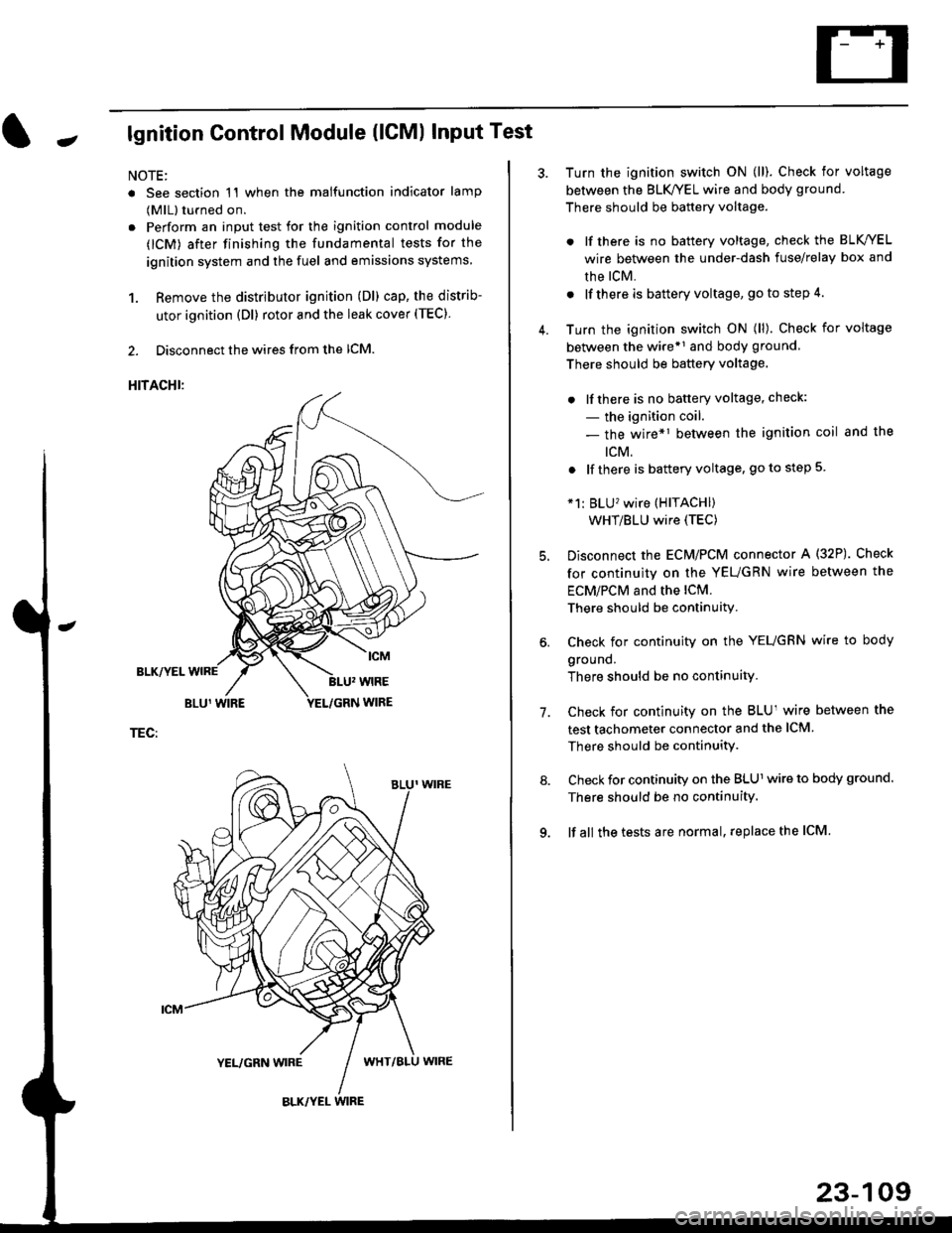
HITACHI:
BLK/YEL
TEC:
Turn the ignition switch ON (ll). Check for voltage
between the BLK/YEL wire and body ground.
There should be battery voltage.
. lf there is no battery voltage, check the BLK/YEL
wire between the under-dash fuse/relay box and
rhe lcM.
. lf there is battery voltage, go to step 4.
Turn the ignition switch ON (ll). Check for voltage
between the wire*r and body ground
There should be battery voltage.
. lfthere is no battery voltage, check:
- the ignition coil.
- the wire*1 between the ignition coil and the
tcM.
. lf there is battery voltage, go to step 5
*1: BLU'�wire (HITACHI)
WHT/BLU wire (TEC)
Disconnect the EcM/PCM connector A (32P). Check
for continuity on the YEUGRN wire between the
ECM/PCM and the lCM.
There should be continuity.
Check for continuity on the YEUGRN wire to body
ground.
There should be no continuity.
Check for continuity on the BLUl wire between the
test tachometer connector and the ICM
There should be continuitY.
Check for continuity on the BLUl wire to body ground.
There should be no continuity.
lf all the tests are normal, replace the ICM
7.
23-109
Page 1580 of 2189

lgnition System
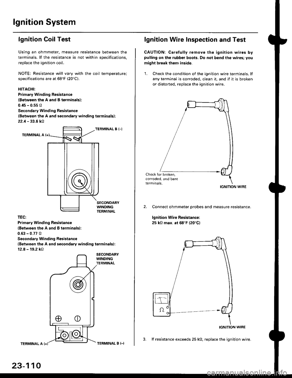
lgnition Coil Test
Using an ohmmeter, measure resistance between the
terminals. lf the resistance is not within soecifications.
replace the ignition coil.
NOTE: Resistance will vary with the coil temperature;
specifications are at 68'F (20'C).
HITACHI:
Primary Winding Resistance
{Betwesn the A and B lerminalsl;
0.45 - 0.55 0
Secondary Winding Resistanc€
(Between the A and secondary winding terminals):
22.1 - 33.6 kA
TERMINAL B {-)
TERMINAL A
TEC:
Primary Winding Resistsnce
{Between the A and B terminalsl:
0.63 - 0.77 0
Secondary Winding Resistance
(Between the A and secondary winding terminals):
12.8 - 19.2 kO
SECONDARYWINDINGTERMINAL
TERMINAL A
23-110
TERMINAL B (-)
lgnition Wire lnspection and Test
CAUTION: Carelully remove the ignition wires bypulling on the rubber boots, Do not bend the wires; you
might break them inside.
'1. Check the condition of the ignition wire terminals. lf
any terminal is corroded, clean it, and if it is broken
or distorted, replace the ignition wire.
Check for broken,corroded, and bentlermrnals.IGNITION WIRE
Connect ohmmeter probes and measure resistance.
lgnition Wire Resistance:
25 k0 max. at 68"F (20"C)
IGNITION WIRE
3. lf resistance exceeds 25 kO, replace the ignition wire.
Page 1582 of 2189
Charging System
Component Location Index
UNDER.HOOD FUSE/RELAY BOX/*Has replaceable ELECTRICAL LOAD II DETECTOR (ELD) UNIT '
Troubleshooting, page 23-1 14Replacement, page 23-120Bectifier Removal, page 23,121Rectifier Test, page 23-122Rear Bearing Replacement, page 23-j24
*ELD unit: USA
CHARGING SYSTEM LIGHT(ln the gauge assembly)Test, page 23- l14
BATTERYTest, page 23-91
ALTERNATOR BELTInspection and Adjustment, page 23-t25
[]
23-112