Page 1632 of 2189
Lighting System
Gomponent Location Index (cont'dl
TURN SIGNAL INDICATOR LIGHTDASH LIGHTS BRIGHTNESSCONTROLLERController Input Test,page 23-119COMBINATION LIGHT SWITCHTest, page 23'165
TURN SIGNAL/HAZARD RELAYInput Test, page 23-'172
HIGH BEAM INOICATOR LIGHT
L ILI LILI LT
rr Lr rJ|r LJ Lr Lr rr !.r rr Lr rr I l-nnr1nr1r1r1r1|-1nn L JJ
r1 n11t'1n Ttr1 r1 - 11 t-1Tt-l T1r-t L.l Lt r-t r-t LJ ! ! LJ LJ ! LJ !J r-l
23-162
Page 1634 of 2189
Lighting System
Circuit Diagram (Canada)
UNDER.HOOD FUSEi RELAY BOXBATTERY
BFAKE SYSTEMLIGHTNTEGRATEDCONTROL UNIT
f-7
I
IFED/GRN
REDiGFN
II
o
Yro*, ,,r'oI LEVEL SW TCH
t |
lclosed : Floal downl
BLK
I
-L..
G401G402
T
.:
BLK
n:
G40lG402
BLK
I
G201
RED/GRN RED/GBN
| .+_
ttL
| | las*,
| \_i-f
Alr
Y,o" r.o" I
liiqff'- |BLK BLK
tl
dT--
G401 G202G402
l\------tr -1
d,$,E" T d
RED/BLU RED/REDiGEN
UNDEF DASH FUSE/RELAY BOX
I
)) N0.20tl0Al)'
No.1g(7.5A)No.50 0A)
, ll-l
llltti /i[ii i,II
ll
llri, zll",ll iu"x
TT
FEDiGRN R€D
tl
!-tl--l
ttuLj
il]-
YEL REDTWHT FED/BLU FED/8LK RED/ BLK
tt++
IIVV| | .DASF L.GHTS . oAB(^rG -TGHTSI I .DAS-LGH'S.TALL'GCTS
| | 33''9+il4[','o L.ENSEoLATELTG'TS
I l-,ro,u,rffl,
^-^^-.*^,{*"'"0-
tlI qsnlq,rr DAYT'ME qUNNINGLIGHTS FES STOF
nd--f)
irt* | | Trt* Iorr Itt I---J \---J-------J
-rGHr
lt*"','
I
I
YEL/BLK
DAYTIMERUNNING LIGHTSCONTROL UNIT
RED/GHN R
I
5
[i.mi:-",,,
Page 1635 of 2189

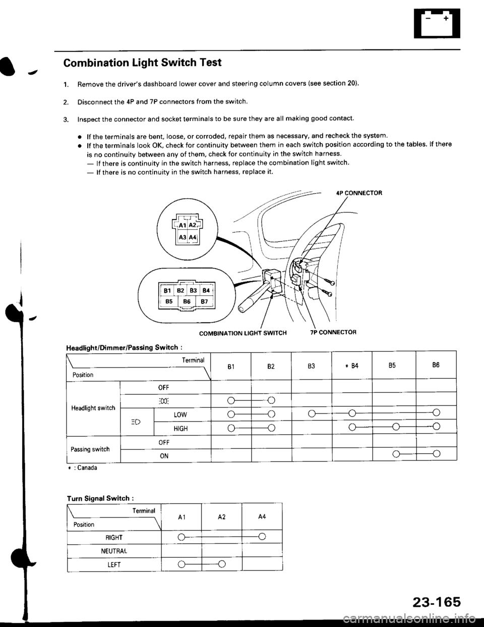
Combination Light Switch Test
1.Remove the driver's dashboard lower cover and steering column covers (see section 20)
Disconnect the 4P and 7P connectors from the switch.
Inspect the connector and socket terminals to be sure they are all making good contact
. lf the terminals are bent, loose. or corroded, repair them as necessary, and recheck the system.
. lf theterminals look OK, check for continuity between them ineach switch position according tothetables lfthere
is no continuity between any of them. check for continuity in the switch harness
- lf there is continuity in the switch harness. replace the combination light switch
- lf there is no continuity in the switch harness, replace it.
2.
4P CONNECTOR
COMBINATION LIGHT SWITCH7P CONNECTOR
HsadlighUDimmer/Passing Switch :
* : Canada
rrr r-l
l(rr mf ItffiTI A3 A11l
Terminal
Position
B182B3*84B586
Headlight switch
OFF
o---o
LOWo---oo-----o
HIGHo-----oo---o
Passing switchOFF
ONo-----o
Turn Signal Switch :
Teminal
;',*;----__\A1A2A4
RIGHToo
NEUTRAL
LEFToo
23-165
Page 1636 of 2189

Lighting System
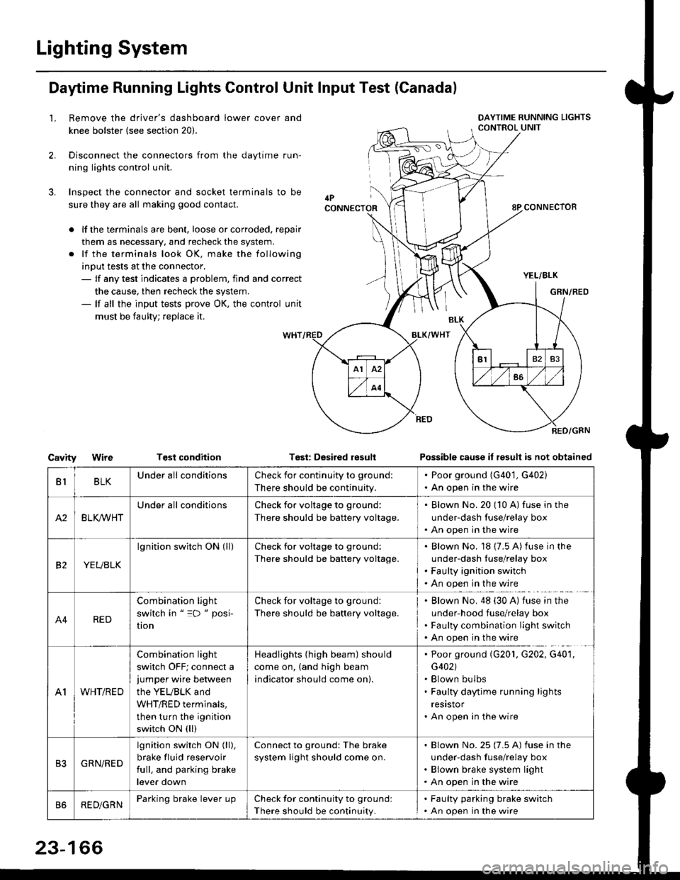
Daytime Running Lights Control Unit Input Test (Canadal
2.
3.
LRemove the driver's dashboard lower cover and
knee bolster (see section 20).
Disconnect the connectors from the daytime run-
ning lights control unit.
Inspect the connector and socket terminals to be
sure they are all making good contact.
lf the terminals are bent, loose or corroded. repair
them as necessary, and recheck the system.
lf the terminals look OK, make the following
input tests at the connector,- lf any test indicates a problem, find and correct
the cause, then recheck the system.- lf all the input tests prove OK, the control unit
must be faulty; replace it.
CavityWireTGst conditionTest: Desired resultPossible cause it result is not obtained
BLKU nderall conditionsCheck for continuity to g.ound:
There should be continuity.
. Poor ground (G401, G402). An open in the wire
A2BLK /VHT
Underall conditionsCheck for voltage to ground:
There should be battery voltage.
Blown No.20 (10 A) fuse in the
under-dash fuse/relay box
An open in the wire
etYEUBLK
lgnition switch ON (ll)Check for voitage to ground:
There should be battery voltage.
Blown No. 18 {7.5 A) fuse in the
under-dash luse/relay box
Faulty ignition switch
An open in the wire
A4RED
Combination light
switch in " =D " posi-
UOn
Check for voltage to ground:
There should be battery voltage.
Blown No. 48 (30 A) tuse in the
under-hood fuse/relay box
Faulty combination light switch
An open in the wire
A1WHT/RED
Combination light
switch OFF; connect ajumper wire between
the YEUBLK and
WHT/RED terminals,
then turn the ignition
switch ON (ll)
Headlights (high beam) should
come on, (and high beam
indicator should come on).
. Poor ground (G201, G202, G40'1,
G402). Blown bulbs. Faulty daytime running lights
resrstor. An open in the wire
GRN/RED
lgnition switch ON (ll),
brake fluid reservoir
full, and parking brake
lever down
Connect to ground: The brake
system light should come on.
Blown No.25 (7.5 A) fuse in the
under-dash f use/relay box
Blown brake system light
An open in the wire
REDiGRNParking brake lever LrpCheck for continuity to groundl
There should be continuity.
. Faulty parking brake switch. An open in the wire
23-166
Page 1643 of 2189
Turn SignallHazard Flasher System
UNOER.DASHFUSE/RELAY 80X
No.12l7 5A)
Gircuit Diagram
UNDER.HOOD FUSE/RELAY 8OX
IJ
l*v
,'|,."J,-(NOt
GRN/YEL
t,
I'RED
I
I
I
II
J
DASH LJGIlTSBRIGHTNESSCONTROLLER
q
BLK
Page 1644 of 2189

Turn SignallHazard Flasher System
1.
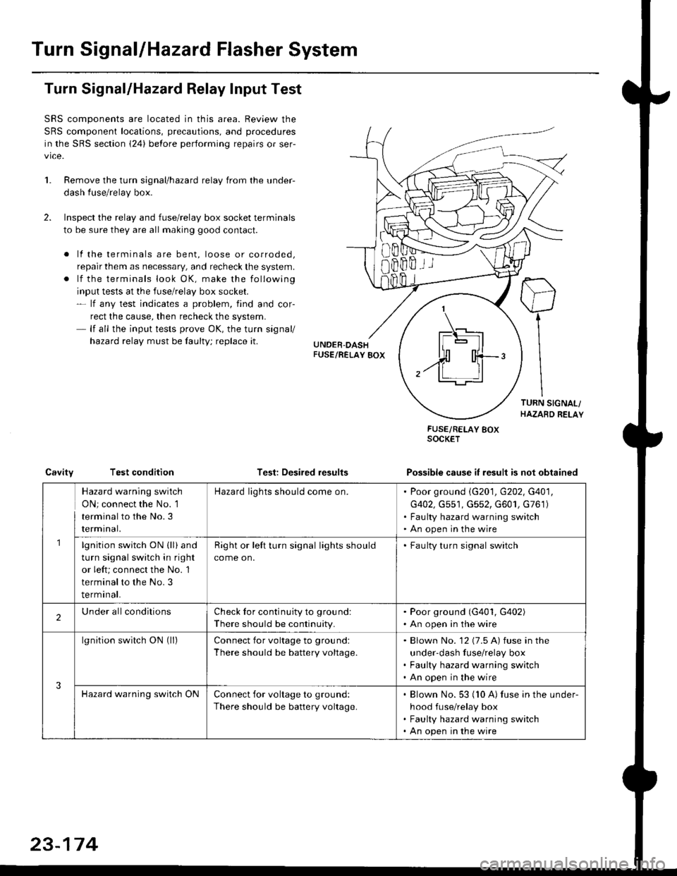
Turn Signal/Hazard Relay Input Test
SRS components are located in this area. Review the
SRS component locations, precautions, and procedures
in the SRS section {24} before performing repairs or ser-
vice.
Remove the turn signal/hazard relay from the under-
dash fuse/relay box.
Inspect the relay and fuse/relay box socket terminals
to be sure they are all making good contact.
. lf the terminals are bent, loose or corroded,
repair them as necessary, and recheck the system.
. lf the terminals look OK, make the following
input tests at the fuse/relay box socket.- lf any test indicates a problem, find and cor-
rect the cause, then recheck the system.- lf all the input tests prove OK, the turn signal/
hazard relay must be faulty; replace it.
Test: Desired results
FUSE/RELAY BOXSOCKET
Possible cause it result is not obtainedCavityTest condition
8Bffii
\_t-E rl.]l
| - lll
n'rl
,.ff T-'t:
Hazard warning switch
ON; connect the No. 1
terminal to the No.3
rermtnat.
Hazard lights should come on.Poor ground \G201, G202, G401,
G402, Gs51, G552, G601, G761)
Faulty hazard warning switch
An open in the wire
lgnition switch ON (ll) and
turn signal switch in right
or left; connect the No. 1
terminal to the No. 3
terminal.
Right or left turn signal lights should
come on.
. Faulty turn signal switch
2Under allconditionsCheck for continuity to ground:
There should be continuity.
. Poor ground (G401, G402). An open in the wire
3
lgnition switch ON (ll)Connect for voltage to ground:
There should be battery voltage.
Blown No. '12 (7.5 A) fuse in the
under-dash fuse/relay box
Faulty hazard warning switch
An open in the wire
Hazard warning switch ONConnect for voltage to ground:
There should be battery voltage.
Blown No. 53 (10 A) fuse in the under-
hood fuse/relay box
Faulty hazard warning switch
An open in the wire
23-174
Page 1648 of 2189
Brake Lights
WNT/GRN
Circuit Diagram
UNDEH HOODFUSEiRELAYBOXBATTERY/-l I No s2 (1sA) |
u/T'\--]-wHrGFNTwfciN_l
tvHORN SYSTEM
INNERTAILL]GHT
GRNMHT
I
AE-'ii,t
Yut#l
IBLK
ffi; I
I l,"l
I I''i
Li;
GRN,4fiHT
l**,,,,I P } BRAKE
Y ilT'
I
I
I
IgLK
I
I:
flatchbackCoupe/SedanSedan 99 mode
ffi; I
i $*i
iri
Li*'']
GRNMHT
I
A b'rt^t-,
Yllf,ll
IBLK
BLK
I
I
I
G601 r Halchback/Coupe/Sedan
BLK
II
II
I
G601 : Haldbackiooup€/Sedan G761 :G601 :G602 :
+ 21W :Coup€/Sedan18W :HalchbackJ I : Wilh cruise control
23-178
Page 1651 of 2189

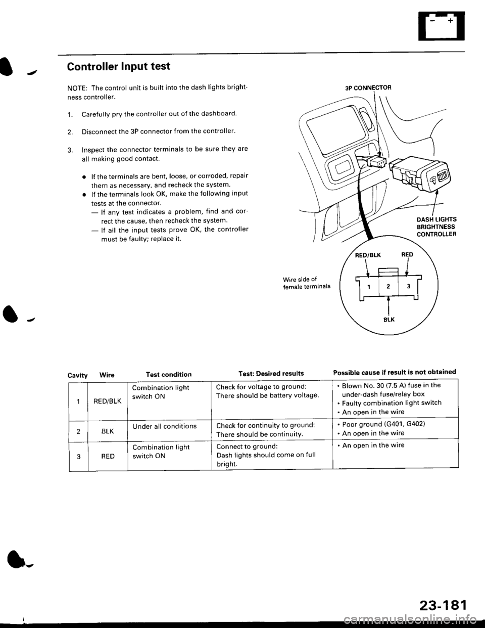
Controller Input test
NOTEr The control unit is built into the dash lights bright-
ness controller.
'1. Carefully pry the controller out of the dashboard.
2. Disconnect the 3P connector from the controller'
3. Inspect the connector terminals to be sure they are
all making good contact.
. lf the terminals are bent, loose, or corroded, repair
them as necessary, and recheck the system.
. lf the terminals look OK, make the following input
tests at the connector.- lf any test indicates a problem, find and cor-
rect the cause, then recheck the system.
- lf all the input tests prove OK, the controller
must be faulty; replace it
Cavity
Wire side of
lemale termlnals
Test condition Test Desited resultsPossible cause if rgsult is not obtainGd
1RE D/B LK
Combination light
switch ON
Check for voltage to ground:
There should be battery voltage.
Blown No.30 (7.5 A) fuse in the
under-dash Iuse/relay box
Faulty combination light switch
An open in the wire
2BLKUnder all conditionsCheck for continuity to ground:
There should be continuity.
. Poor ground (G401, G402)
. An open in the wire
RED
Combination light
switch ON
Connect to ground:
Dash Iights should come on full
bright.
. An open in the wire
23-181