Page 1735 of 2189
l
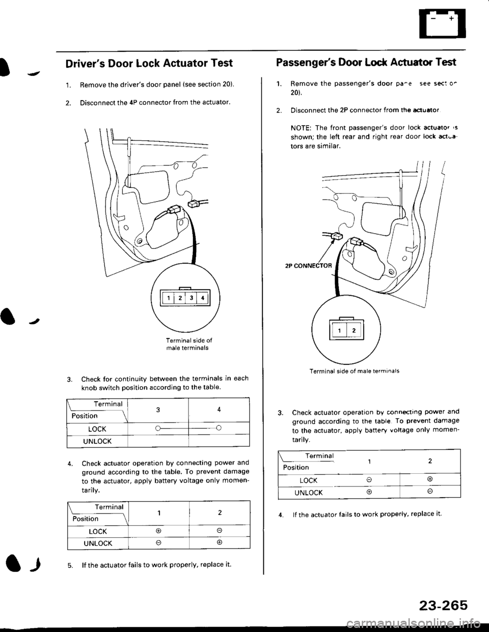
Driver's Door Lock Actuator Test
1. Remove the driver's door panel (see section 20).
2. Disconnect the 4P connector from the actuator.
J
Terminalside ofmale terminals
3. Check for continuity between the terminals in each
knob switch position according to the table.
4. Check actuator operation by connectlng power ano
ground according lo the table. To prevent damage
to the actuator, apply battery voltage only momen-
tarilY.
l-l5. lf the actuator fails to work properly. replace it
23-265
Terminal
F""lti* - lll
LOCKo
UNLOCK
Terminal
Fo"JJ'-lrlon';" -ll1
LOCK@o
UNLOCK
Passenger's Door Lodr Actuator Test
1.
2.
Remove the passenger's doo. pa^e see sect o'
201.
Disconnect the 2P connector from lhq aclualor
NOTE: The front passenger's door lock actualor ,s
shown; the left rear and right rear door lock act{,a
tors are similar.
Terminal side ol male terminals
3. Check actuator operation by conneclrng power and
ground according to the table To prevent damage
to the actuator, apply banery voltage only momen-
tarily.
4. lf the actuator Iails to work properly, replace it.
Terminal,2Position
LOCK O@
UNLOCK Oo
Page 1747 of 2189
)
Wiring Precautions
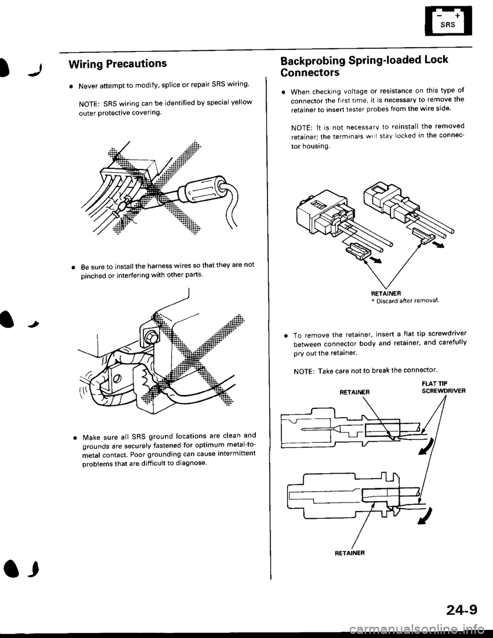
. Never attempt to modify, splice or repair SRS wiring'
NOTE: SRS wiring can be identified by special yellow
outer Protective covering.
8e sure to install the harness wires so that they are not
oinched or interfering with other parts.
t
Make sure all SRS ground locations are clean and
grounds are securely fastened for optimum metal-to-
metal contact. Poor grounding can cause intermittent
problems that are difficult to diagnose.
a,
24-9
Backprobing Spring'loaded Lock
Gonnectors
. When checking voltage or resistance on this type of
connector the flrst time, it is necessary to remove lne
retainer to insert tester probes from the wire side.
NOTE: lt is not necessary to reinstall the removed
retainer; the terminals wi I stay locked in the connec-
tor housrng.
To remove the retainer, insert a flat tip screwdriver
between connector body and retainer, and carefully
pry out the retainer.
NOTE: Take care not to break the connector.
FLAT TIPSCBEWDRIVER
RETAINER* Discard after removal.
RETAINER
Page 1748 of 2189
Preca utions/Procedures
Spring-loaded Lock Connector
Some SRS system connectors have a spring-loaded lock.
Disconnecting
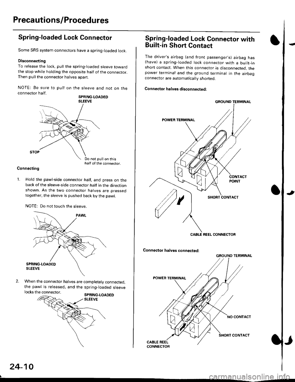
To release the lock, pull the spring-loaded sleeve towardthe stop while holding the opposite half of the connecror.Then pull the connector halves apart.
NOTE: Be sure to pull
connector half.
on the sleeve and not on the
SPRING-LOADEOSLEEVE
Do not pull on thishalf of the connector.
Connecting
1. Hold the pawl-side connector half, and press on theback of the sleeve-side connector half in the directionshown. As the two connector halves are pressed
together, the sleeve is pushed back by the pawl.
NOTE: Do not touch the sleeve.
When the connector halves are completely connected,the pawl is released, and the spring-loaded sleevelocks the connector.SPRING.LOADEDSLEEVE
24-10
Spring-loaded Lock Connector with
Built-in Short Contact
The driver's ajrbag (and front passenger,s) airbag has(have) a spring-loaded lock connector with a builr-inshort contact. When this connector is disconnected, thepower terminal and the ground terminal in the airbaaconnector are automatically shoned.
Connector halves disconnected:
SHORT CONTACT
Conneqtor halves connected:
GROUND TERMINAL
CABLE REEL CONNECTOR
GROUND TERMINAL
Page 1755 of 2189
l
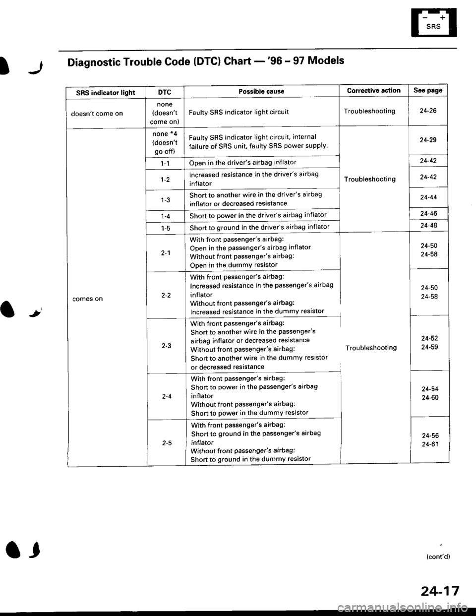
Diagnostic Trouble Code (DTG) Chart -'96 - 97 Models
t
SRS indicator lightDTCPossible causeCorrectiv6 actionSae page
doesn't come on
none(doesn't
come on)
Faulty SRS indicator light circuitTroubleshooting24-26
comes on
none *4
(doesn't
go off)
Faulty SRS indicator light circuit, internal
failure of SRS unit, faulty SRS power supply.
Troubleshooting
24-29
1-1Open in the driver's airbag inflator24-42
lncreased resistance in the driver's aarbag
inflator24-42
l-3Short to another wire in the driver's airbag
inflator or decreased resistance
Short to Dower in the driver's airbag inflator
Short to ground in the driver's airbag inflator
24-44
1-424-46
1-524-48
2-1
With front passenger's airbag:
Open in the passenger's airbag inflator
Without front Passenger's airbag:
ODen in the dummy resistor
24-50
24-54
With front passenger's airbag:
Increased resistance in the passenger's airbag
inflator
Without front Passenger's airbag:
lncreased resistance in the dummy resistor
24,50
24-54
2-3
With front passenger's airbag:
Shon to another wire in the passenger's
airbag inflator or decreased resistance
Without tront passenger's airbag: Troubleshooting
Short to another wire in the dummy resistor
or decreased resistance
24-52
24-59
2-4
With front passenger's airbag:
Short to power in the passenger's airbag
inJlator
Without front Passenger's airbag:
Short to power in the dummy resistor
24-54
24-60
With front passenger's airbag:
Short to ground in the passenger's aarbag
inflator
without front passenger's airbag:
Short to ground in the dummy resistor
24-56
24-61
(cont'd)
24-17
a,
Page 1757 of 2189
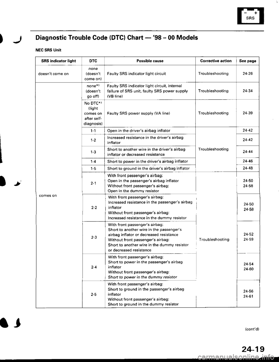
)Diagnostic Trouble Code (DTC) Chart -'98 - 00 Models
NEC SRS Unit
Ir
SRS indicator lightDTCPossible causeCorrestive actionSee page
doesn't come on
none
(doesn't
come on)
Faulty SRS indicator light circuitTroubleshooting24-26
comes on
none*3
(doesn't
go off)
Faulty SRS indicator light circuit, internal
fallure of SRS unit, faulty SRS power supply
(VB line)
Troubleshooting24-34
No DTC*3(lis ht
comes on
after self-
diagnosis)
Faulty SRS power supply (VA linelTroubleshooting24-39
l-1Open in the driver's airbag inflator
Troubleshooting
24 42
Increased resistance in the driver's airbag
inflator24-42
Short to another wire in the driver's airbag
inflator or decreased resistance24-44
't -4Short to power in the driver's airbag inflator24-46
t-5Short to ground in the driver's airbag inflator24-48
With front passenger's airbag:
Open in the passenger's airbag inflator
Without front passenger's airbag:
Open in the dummv resistor
24-50
24-54
With front passenger's airbag:
Increased resistance in the passenger's airbag
inflator
Without front passenger's airbag:
Increased resistance in the dummy resistor
24-50
24-58
with front passenger's airbag:
Short to another wire in the passenger's
airbag inflator or decreased resistance
Without front passenger's airbag:
Short to another wire in the dummy resistor
or decreased resistance
Troubleshooting
24-52
24,59
2-4
With front passenger's airbag:
Short to power in the passenger's airbag
inflator
Without front passenger's airbag:
Shon to power in the dummy resistor
24-54
24-60
With front passenger's airbag:
Short to ground in the passenger's airbag
inflator
Without front passenger's airbag:
Short to ground in the dummy resistor
24-56
24-61
(cont'd)
24-19
l,
Page 1759 of 2189
)r
l,.l
I
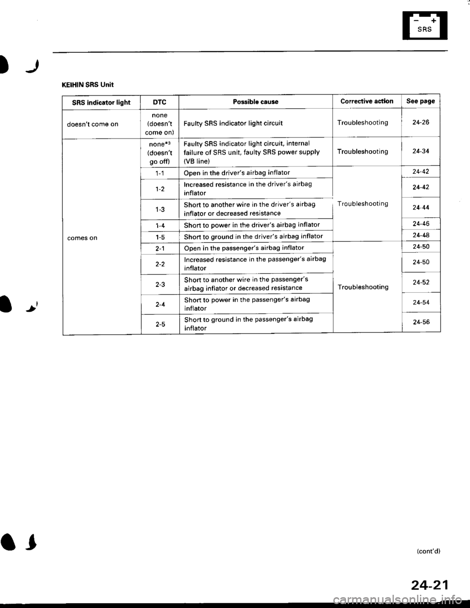
KEIHIN SRS Unit
SRS indicator lightDTCPossible cau3eCorrective astionSee page
doesn't come on
none
(doesn't
come on)
Faulty SRS indicator light circuitTroubleshooting24-26
comes on
none*3
(doesn't
go offl
Faulty sRs indicator light circuit, internal
failure of SRS unit, faulty SRS power supply
{VB line)
Troubleshooting24-34
Open in the driver's airbag inflator
Troubleshooting
24-42
1-2Increased resistance in the driver's airbag
inflator24-42
1-3Short to another wire in the driver's airbag
inflator or decreased resistance24-44
1-4Short to power in the driver's airbag inflator24-46
1-5Short to ground in the driver's airbag inflator24-44
2-1Open in the passenger's airbag inflator
Troubleshooting
24-50
Increased resistance in the passenger's airbag
inflator24-50
Short to another wire in the passenger's
airbag inflator or decreased resistance24-52
2-4Short to power in the passenger's airbag
inflator24-54
Short to ground in the passenger's airbag
inflator24-56
(cont'd)
24-21
Page 1761 of 2189
)r
l-J
SIEMENS SRS Unit
SRS indicator lightDTCPossible cause Corregtive astionSee page
doesn't come on
none(doesn't
come on)
FaulW SRS indicator light circuitTrou bleshooting24-26
comes on
none*3
(doesn't
go ofl)
Faulty SRS indicator light circuit, internal
failure of SRS unit, faulty SRS power supply
{VB line)
Troubleshooting24-34
1-1Open or increased resistance in the driver's
airbag inflator
Troubleshooting
24,42
1-3Short to another wire in the driver's airbag
inflator or decreased resistance24-44
1-4Short to power in the driver's airbag inflator24-46
Shon to ground in the driver's airbag inflator24 48
2-1Open or increased resistance in the passengers
airbag inflator
Troubleshooting
24-50
2-3Short to another wire in the passenger's
airbag inflator or decreased resistance24-52
2-4Short to power in the passenger's airbag
inflator24-54
2-5Short to ground in the passenger's airbag
inflator24-56
,-. ^
l) t (cont,d)
24-23
d
Page 1765 of 2189
)
From page 24-26
(A)
From page 24-26
(B)DASHBOARD WIRE HARNESS
5P CONNECTOR
It
MAIN WIRE HARNESS2,rP CONNECTOR
DASHAOARD WIREHARNESS 2irPCONNECTOR
c41 1
(cont'd)
24-27
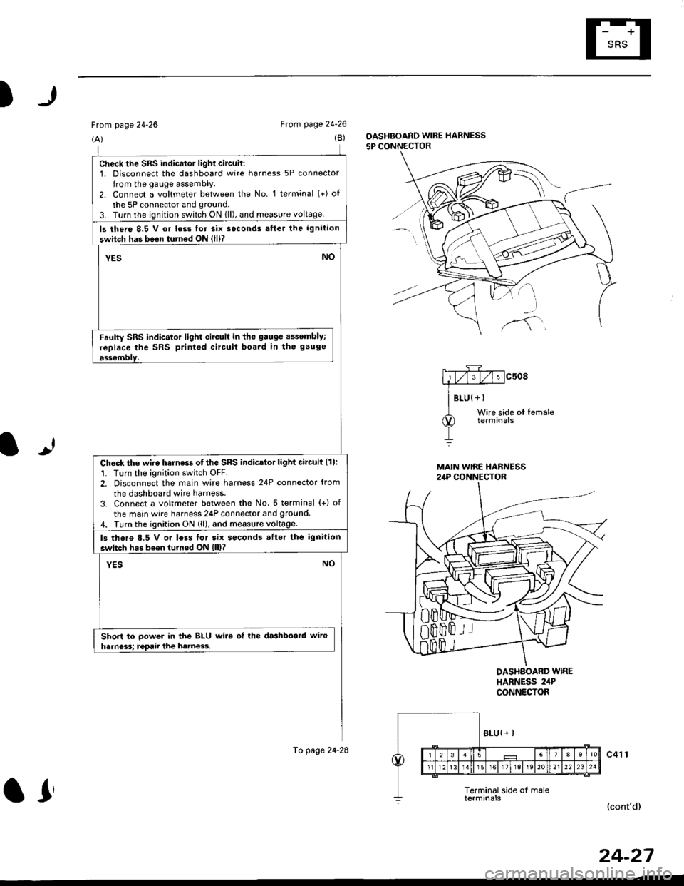
check the sRs indicator light circuit:1. Disconnect the dashboard wire harness 5P connector
from the gauge assembly.2. Connect a voltmeter between the No. 1 terminal (+) of
the 5P connector and ground.
3. T!rn the ignition switch ON 1ll), and meas!re voltage.
ls there 8.5 V or loss lor six seconds atter the ignition
swilch has been turned ON {lll?
YESNO
Faulty SRS indicator light circuit in the gauge e$embly;
replace the SRS printed circuit boa.d in tho gauge
ass€mblY.
Check the wire harness otthe SRS indicator light circuil {1):'1. Turn the ignition switch OFF.2. Disconnect the main wire harness 24P connector from
the dashboard wire harness.
3. Connect a voltmeter between the No. 5 terminal {+) of
the main wire harness 24P connector and 9round4. Turn the ignition ON (ll), and measure voltage.
ls thore 8.5 V or lcss tor tix second3 .Itor the ignition
switch has b6en turned ON lll)?
YESNO
Short to oower in the BLU wire ol the dashboald wiroharness; rgpaii the ham€ss.
To page 24-28
ar