1999 HONDA CIVIC charging system
[x] Cancel search: charging systemPage 1607 of 2189
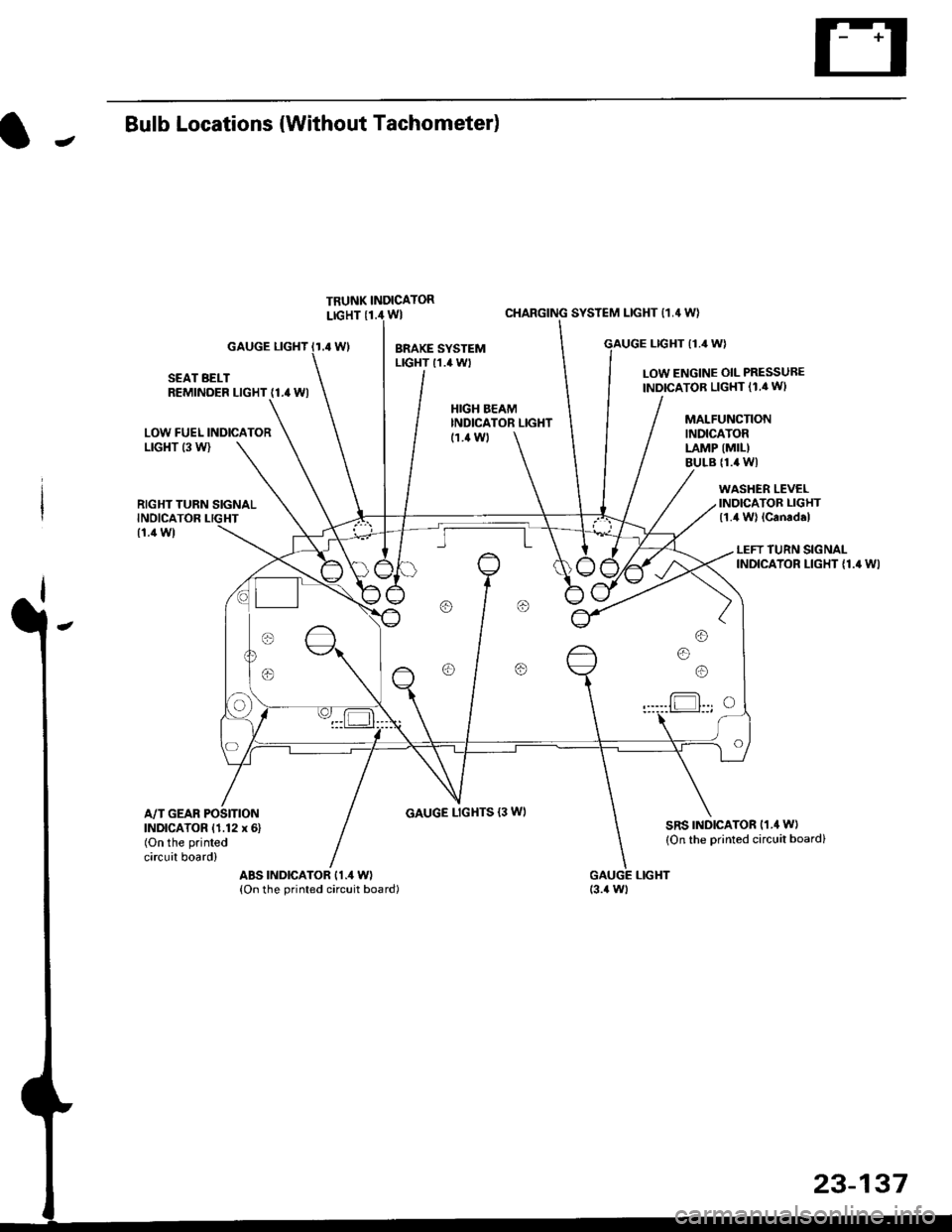
JBulb Locations {Without Tachometer)
TRUNK INDICATORLIGHT {1.i1W}
.4 Wl
CHARGING SYSTEM LIGHT 11,4 W}
LTGHT (1.4 W)GAUGE LIGHT
SEAT BELTREMINDER LIGHT (1.4 WI
LOW ENGINE OIL PRESSUBE
INDICATOB LIGHT (1.4 WI
LOW FUEL INDICATORLrGl{T (3 W)
RIGHT TURN SIGNALINOICATOR LIGHT
(1.1Wt
GAUGE LIGHTS {3 WI
WASHER LEVELINDICATOR LIGHT{1.4 W} lcanad.l
HIGH BEAMINDICATOR LIGHTMALFUNCTIONINDICATORLAMP (MIL)
BULB {1.4 WI
{1.ilW)
LEFT TURN SIGNALINDICATOR LIGHT {1.4 WI
A/T GEAR POSITIONINDICATOR (1.12 x 6)(On the printed
circuit board)
sRs TND|CATOR 11.4 W)
{On the Drinted circuit board}
aBs tNDtcAToR t1.4 W)(On the printed circuit board)(3.{ Wt
o/ o \7 o
23-137
Page 1817 of 2189

Contents
How to Use This Manual ICircuit Schematics (see Circuit Index)Fuse/Relaylnformation 6Ground-to-Componentslndex 6-6ComponentLocationPhotooraohs 201Conriector Views 202
Circuit Index
Accessory power socket 155Air conditionerAir delivery'96198 models 61'99-'00 models 61-2Blower controls'96198 models 60'99100 models 60-1Compressor controls 62Fans 63Anti-lock brake system (ABS) 44A/T gear position indicatorCVT 89All except CVT 89-1Automatic transmission controlsAll '96-'98 models except CVT and GX 39All '99100 models except CVT 39-8All GX models 39-8'96-'�98 CVT 39-4'99100 cw 39-12Back-up lightsCoupe and Sedan 110Hatchback l'10-1Brake lightsAll Coupes and'96-'98 Sedans 110-15'99-'00 Sedans 110-16Hatchback 110-17Brake system indicator light'96198 models 7'1'99100 models 71-1Ceiling light 114-3Charging system 22Condenser fan 63Console lights 114Cruise control 34Dash lights 114Daytime running lights 110- 13Engine coolant temperature gauge 81-1Fog lights 110-10Front parking lights 110-2Fuel gauge 81-1Fuse/relay boxUnder-dash 6Under-hood 6-4Underhood ABS 6-3Gauges 81Ground distribution 14Ground-to-Componentslndex 6-6Hazard warning lightsAll except '99100 Sedans 110-6'99100 Sedans 110-8Headlights 110-12Headlight switch 100Heater - See Air ConditionerHorn'96197 models 40'98 model 40-1'99100 models 40-2lgnition key reminder 73lgnition systemAll '96198 models except Dl685 20All '99100 models except D16Y5 with Mn 2O-2All D1685 engines 20-2'99-'00 D 16Y5 with M/T 20
lndicators 80Integrated control unit 70lnterlock systemAll except'96J98 CVT 138'96198CVT 138-1License plate lightsAll Coupes and '96-'98 Sedans I l0-3'99100 Sedans 1 10-4Hatchback 110-5Low fuel indicator light 74Moonrool'96197 models |22'98-'00 models 122-1Odometer 81Oil pressure indicator light 80-3Power distributionBattery to ignition switch, fuses, and relaysFuses to relays and components 10-2Power door locksAll models without keyless entry 130'96-'98 models with keyless entry 130-2'99100 models with keyless entry 130-12Power mirrorsWithout detogger 141With defogger '141-2
Power windows 120Programmed fuel injection system (PGNr-Fl)All '96-98 models except D1685 23All '99-'00 models except D16Y5with M/T and D1685 24All D1685 engines 25'99100 D16Y5 with M/T 23Radiator fan 63Rear window defogger'96-,98 models 64'99100 models 64-1Seat belt reminder 73Security system'96.'98 USA HX, LX, EX 133'96-'98 Canada EX, Si 133'99TOO USA HX, LX, EX, DX.V Si 133-4'99100 Canada EX, Si 133-4All CX and DX models 133-8Speedometer 81Starting systemA./T (All except Dl685) 21A"/r (D16Bs) 21-1Manualtransmission 21-2Slereo sound system 150Supplemental rastraint system (SRS) 47Tachometer 81TailliqhtsAllboupes and'96-'98 Sedans 110-3'99100 Sedans 1 10-4Hatchback 110-5Trunk light 114-3Turn signal lightsAll except'99100 Sedans 110-6'99-'00 Sedans 1 10-8Vehicle speed sensor (VSS) 33Wiper/washerFront 91Rear 92
10
Page 1878 of 2189
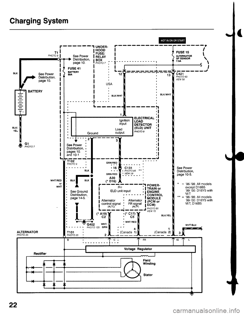
Charging System
See PowerDistribution,pag6 10.
UNDER-HOODFUSE/RELAYBOX
FUSE 15ALT€IIIAIONsP SEII|SOF7.5A
I
t
USA
' BLKAVHTBLKI"VI/HT
-)l,------J
vtEw 50
See PowerDistribution,page 10-5.
* = 96-98rAllmodelsexcept 01685'99 '00: D16Y5 withi.4/T** = '96'�98: All models'99r00: D16Y5 witht\4/T, D1685
BATTERY
ALTERNATOR
See PowerDiskibution,page 10.
FUSE 41BATTEFY804
T101
L-----
ELECTFICALLOADDETECTOR(ELO) UNIT
'l
;l
:l
:l;l
:l
tl,l
:l
:l
G1!
- -I POWER-I -. ^ "'.1 , I rnlrn or
(.A1e)Y '('� C17)c2[ : cs
i ELD unit input i ietCrHe! ' ! coNrRoLI I MODULEI Art€rnator : lllerlato.r I (PCM or
i controrsrsnar i t",fl?il"' a:"^y]L- ----,1- - - - J Pq_oro 3'
*. B,'"',1; :.i
i:1E15_'_
_. i
GFN/FED
r i6
GFN/RED
A30
f D16)WHT/REO*Fi
See Ground IDistribution, Ipage 14-5. I
YT
L]
' ""- PHA|O
,.^;?f, :('c;3)T BLXYEL
I i 'r", ".o II'HT/ ll ' U,zscnrl :-' oi .l
, L : (c'r9ill-_- 'c11" 2)u
l9nitionrnput
LOaO
Ground ourpur
22
Page 1887 of 2189
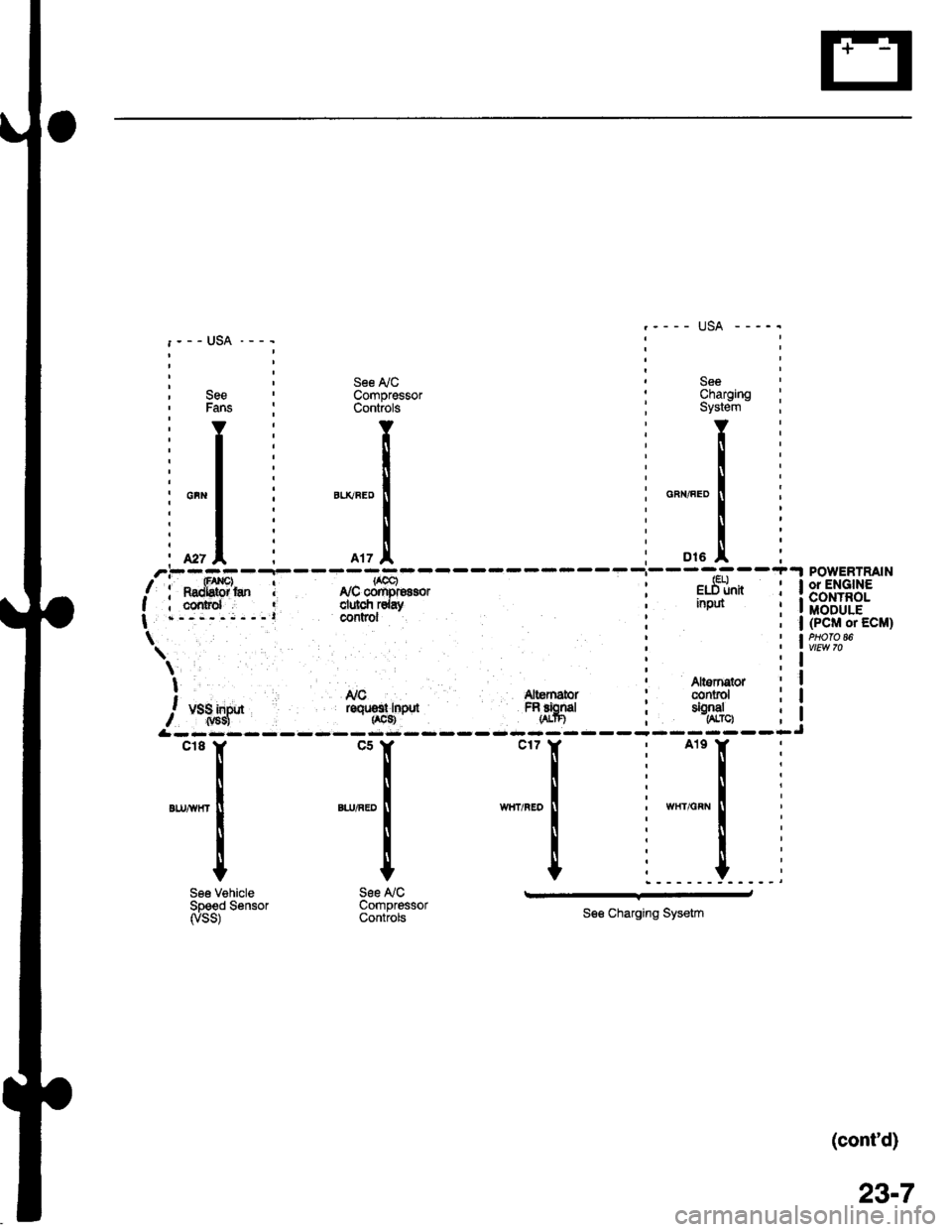
: , See ly'C ' See, See ' Compressor : Charging' Fans : Controls ; System
'YI Y:Y
:l: ll:[
il: l:l
i*"1 i "*"."1 : o"",".o1
, r | : -^*l
ili I i Ii. *, I i rrz.l, ; ot. I'.--..--r-
/i**fffi'* I r,rcffi"oro, i e.St*I ; cornrd ' clulcfi rday ' nput
| .-,---;---l COntrOl
\'
\;t ' Altsrnqtor! Nc Altemator : conrol
/, u.1;lf* roqrsr rnpd FRfrgd ; tSJ",
&rrr:rr
SeeCharornoSystein - :
Y:
!i
u".o I i
i:
o,. .!, iPOWERTRAIN
l*.]["n i 13'"',1+?3.': I MODULE; | (PcM or EcM)
i lw,t?'"
Altornstor ; Iconrol i I
$:--lJ
"''I
',n,-
I
I
See VehicleSpeed Sensorryss)
*[
".,^."
!
I
t
See NCCompressorControls
.r_l
See Charging Sysetm
(cont'd)
23-7
Page 1900 of 2189
i--I,*.;----l
I I ffl* s€€ Pow€' I
!---h=js:q-l
r'1ltii*",
! il"Jiisa"
;ll
i-[*-*"".""--l
! @ffi[+[ffI. !
! Ir6rer i
L--L-,sr@lc5Y
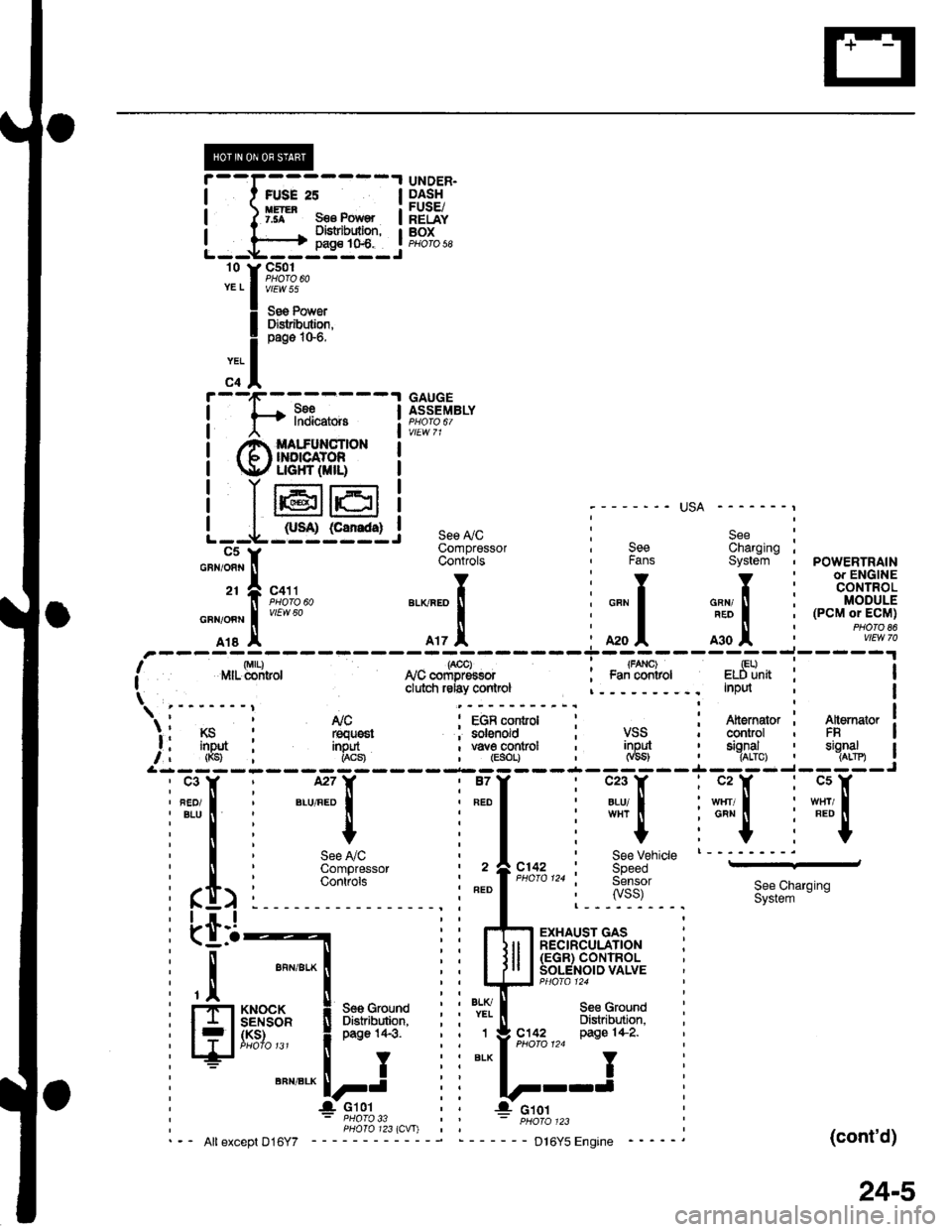
UNDER.DASHFUSE/RELAYBOXPHO|O 58
GAUGEASSEMBLY
;------- USA -------,
see ly'c i S"" :Compressor , See Charging ;Controts , Fans System , POWERTRAIN-
li*t*rr,, ".o^.of, i """f """,tr' i tff'$fit!
Tl,!,
"0o -;;l
i ;;l ^*l i
n"""j.F,rH;
Irs I A17 A :A2oA moA :
,'-----ri;)---7ol------T-;;l----,il--i-----'r,' r',lrr- di-ritror lvc "orip-E""or : Fa; ;;iror eldiinit : II clutci relay conlrcl InPd I\tri---"---i t!9--. i-;ter";--I i{r,*+-i 1s"'*.'lr I t'lc : EGR control : : Atternator I A[emator ]'. I KS : requ6st ; solenoid ; VSS ' control , FR Ia , inDut : inout , \iave control , inpul , sional ' sianal I, , (Ks) i i*"1 , (Esor, _jt,__.j-_JgL-.j__ ,^:_j3------- --- --- -- -.4- -- -- -,1-- - -
i"fiti".,ff:l i"111 iffilifili"F"l
i*l i + i I i
"+
i-"1 :''"1T'See LiC , I ' See vehicle t--'---'-'
ComOressor , 2 ^C142 : SpeedContiofs | | PHoro124 i Sensor
i ft> i :"::l
' ".o
|
",o,o,,0
i lisi: 3i&S**n,"n
i Lti-t i i rh;ry,'s;3+r"" i
: I ""n,".*l iiltll lS'"",.?^8"'$lli'til ""n'"'*! iil-il]J5ff#f."ruuu
i ll.,*'o.* ! *o,o,no i i l'.lT- seecround
: FflSI8$" i Btr"lifiiJ}': i i *i[ Bi,i"EL'""
; f lJffi""' !**;' i i":-lei'u!,7,,"
ws{u'
(cont'd)
24-5
Page 2114 of 2189
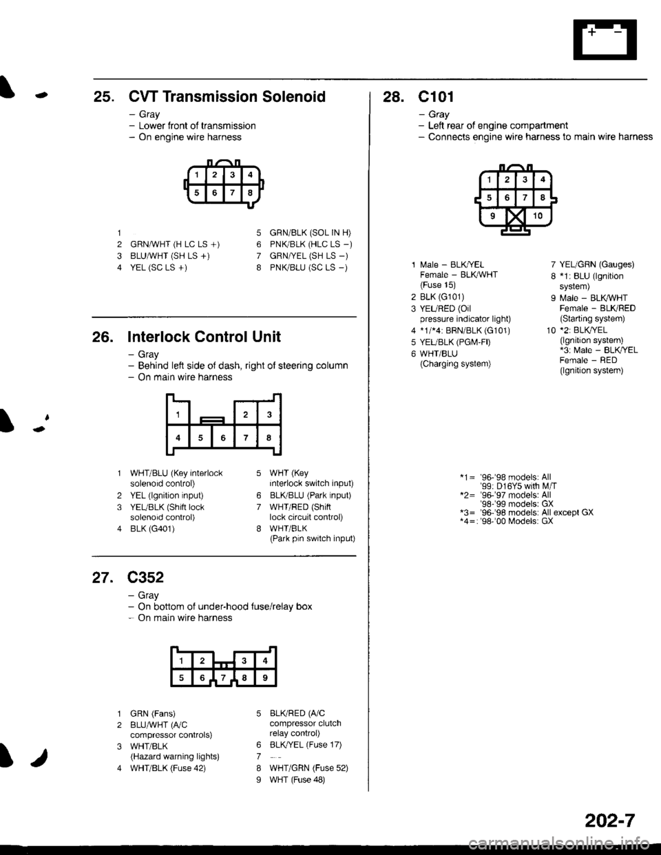
-25. CW Transmission Solenoid
- Gray- Lower front of transmission- On engine wire harness
1
2 GRNAVHT (H LC LS +)
3 BLUAVHT (SH LS +)
4 YEL (SC LS +)
5
6
7
8
GRN/BLK (SOL IN H)
PNK/BLK (HLC LS _)
GRN|VEL (SH LS -)
PNK/BLU (SC LS _)
26. Interlock Control Unit
- Gray- Behind left side oJ dash, right of steering column- On main wire harness
1
7
2
3
4
WHT/BLU (Key interlocksolenoid control)
YEL (lgnition input)
YEUBLK (Shift locksolenoid control)
BLK (G401)
WHT (Key
interlock switch input)
BLKBLU (Park lnput)
WHT/RED (Shinlock circuit control)
WHI/BLK(Park pln switch input)
6
7
27. C352
- Gray- On bottom of under-hood {use/relay box- On main wire harness
1
789
I
1
2
3
4
GRN (Fans)
BLUAVHT (fuC
compressor controlS)
WHT/BLK(Hazard warning lights)
WHT/BLK (Fuse 42)
BLKRED (A/Ccompressor clutchrelay control)
BLK,/YEL (Fuse 17)
WHT/GRN (Fuse 52)
WHT (Fuse 48)
6
7
8
I
28. C101
- Gtay- Left rear of engine compartment- Connecls engine wire harness to main wire harness
1 l\,4ale - BLK/YELFemale - BLK,ryVHT(Fuse 15)
2 BLK (G101)
3 YEURED (Oilpressure indicator light)
4 *1/*4: BRN/BLK (G101)
5 YEUBLK (PGI\4,FD
6 WHT/BLU(Charging system)
7 YEL/GRN (Gauges)
I *1: BLU (lgnition
sYstem)
9 Male - BLK VHTFemale - BLKRED(Slarting system)
10 *2: BLKryEL(lgnition system)*3: Male - BLK/YELFemale - RED(lgnition system)
*1= 96-'98 models: All'99: D16Y5 with M,iT*2= '96-'97 models: All'98-'99 modelsr GX*3= '96-'98 models: All except GX*4=: '98''00 Models: GX
202-7
Page 2122 of 2189
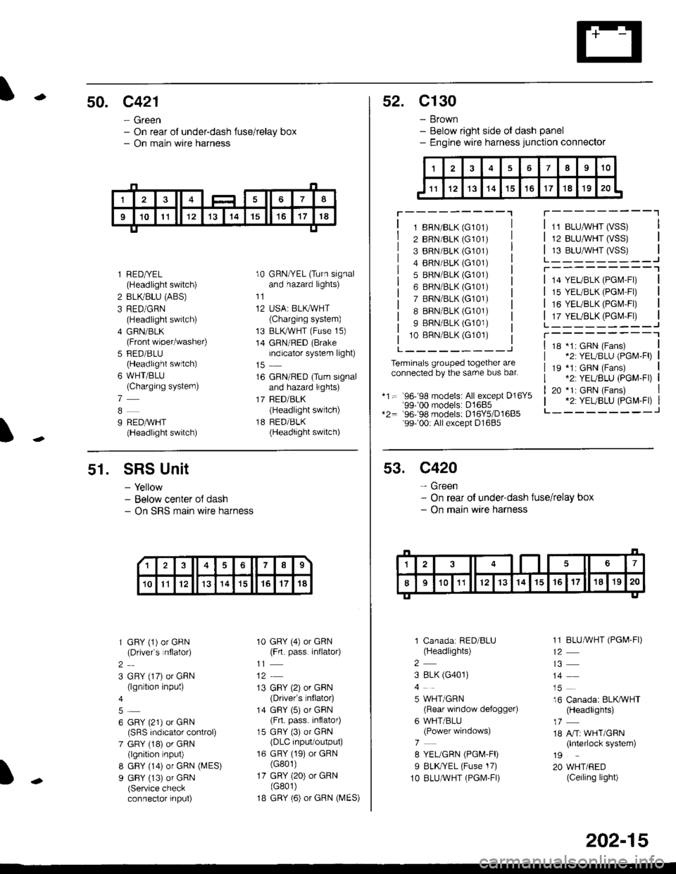
-50. c421
- Green- On rear of under-dash fuse/relay box- On main wire harness
I
l RED/YEL(Headlight switch)
2 BLIVBLU (ABS)
3 RED/GRN(Headlight switch)
4 GFIN/BLK(Front wiper/washer)
5 FED/BLU(Headlight swrtch)
6 WHT/BLU(Charging systern)
7
9 REDAVHT(Headlight switch)
10 GRN/YEL (Turn signaland hazard lights)
11
12 USA: BLKAVHT(Charging system)
13 BLKryVHT (Fuse 15)
14 GRN/RED (Brake
indicator system light)
16 GRN/RED (Turn signaland hazard lights)
17 BED/BLK(Headlight switch)
18 RED/BLK(Headlight switch)
52. C130
- Brown- Below right side ot dash panel- Engine wire harness junction connector
T---------"1
1 8RN/BLK (G101)
2 BRN/BLK (G101)
3 BRN/BLK (G101)
4 BRN/BLK (G101)
5 BRN/BLK (G101)
6 BRN/BLK (G101)
7 BRN/BLK (G101)
I BRN/BLK (G101)
9 BRN/BLK (G101)
10 BBN/BLK (G101)
L---------J
Terminals grouped together areconnected by the sarre bus bar.
*1= 96- 98 models: All except D16Y5'99-'00 models: D1685*2= 96-98 models: D16Y5/D1685'99- 00r All except D1685
11 BLUMHT (VSS)
12 BLU,ryVHT (VSS)
13 BLU,^/VHT (VSS)L_-_____--Jr---------'1
14 YEL/BLK (PGl\4-Fl)
15 YEL/BLK (PGr\4'Fr)
16 YEUBLK (PGI\4,FI)
17 YEUBLK (PGr\4,Fr)L______---JT----------118 *1: GRN (Fans)*2: YEUBLU (PGM-Fl)
19 *1: GRN (Fans).2: YEUBLU (PGM-Fl)
20 *1: GRN (Fans).2: YEUBLU (PGM-Fl)_______--J
51. SRS Unit
- Yellow- Below center oJ dash- On SRS marn wire harness
1 GFY (1) or GRN(Drivefs nflator)
2
3 GRY (17) or GRN(lgn tion input)
6 GRY (21) or GRN(SRS indicalor control)
7 GRY (18) or GRN(lgnition nput)
8 GBY (14) or GRN (MES)
9 GBY (13) of GRN(Service checkconnector input)
10 GRY (4) or GRN(Frt. pass. inflato4
11
13 GBY (2) or GRN(Drivefs nflator)
14 GBY (5) or GRN(Frt. pass. inflator)
15 GRY (3) or GRN(DLC input/output)
16 GRY (19) or GRN(G801)
17 GRY (20) or GRN(G801)
1B GRY (6) or GRN (MES)
13678
10Il12131415't7't8
53. C420
- Green- On rear of under-dash fuse/relay box- On main wire harness
1 Canadar RED/BLU(Headlights)
2
3 8LK (G401)
5 WHT/GRN(Rear window defogger)
6 WHT/BLU(Power windows)
7
8 YEL/GRN (PGM-FD
I BLK//EL (Fuse 17)
1O BLUAVHT (PGM,FI)
1 1 BLUMHT (PGI,4-FI)
14
16 Canada: BLKAVHT(Headlights)
18 A/Tr WHT/GRN(lnterlock system)
19
20 WHT/RED(Ceiling light)
202-15
Page 2123 of 2189
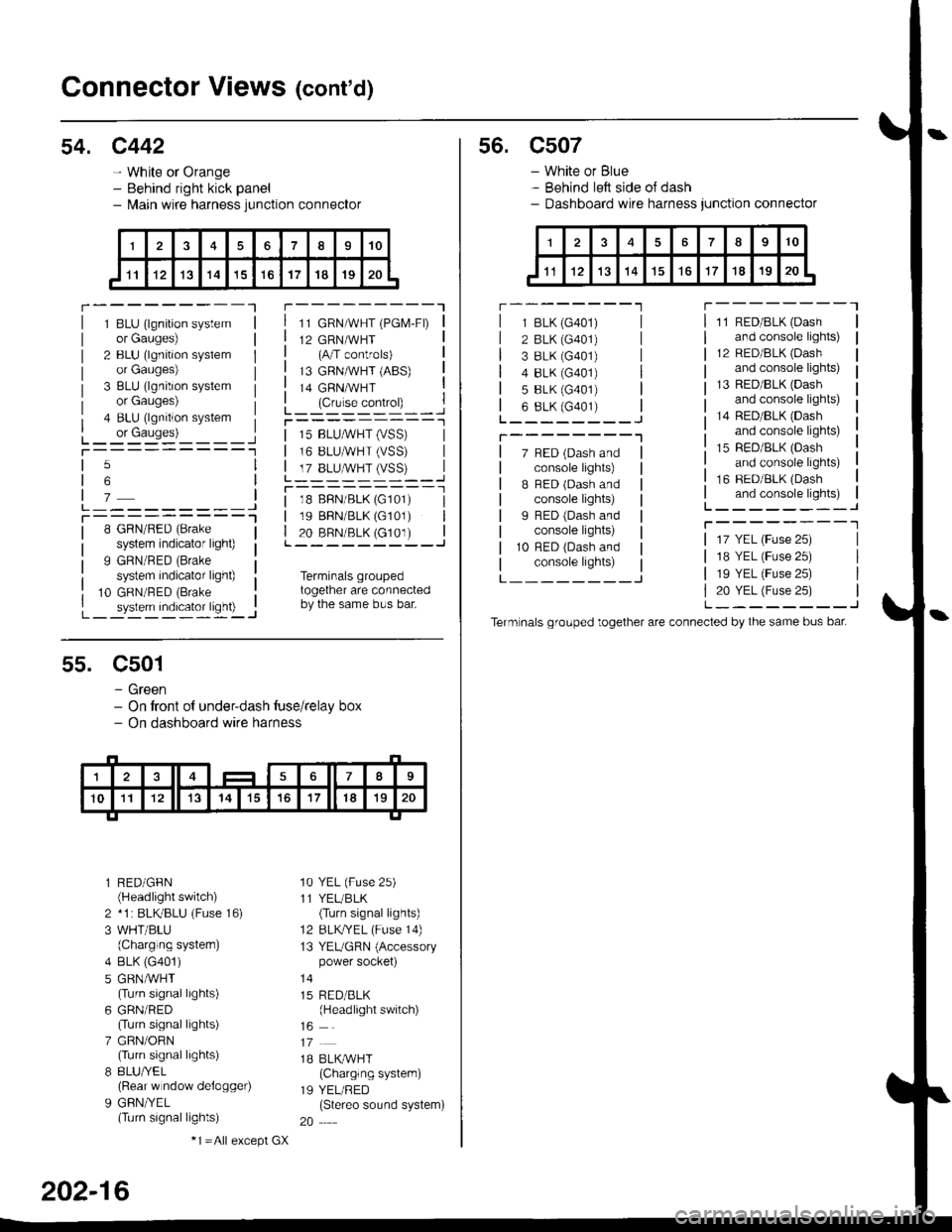
Connector Views (cont'd)
54. c442
- White or Orange- Behind right kick panel- l\,lain wire harness junction connector
r---------Tr---------"1
1 BLU (lgnition systemor Gauges)
2 BLU (lgnition syslemor Gauges)
3 BLU (lgnition systemor Gauges)
4 BLU (lgnition system
L_ or causes)L_-:-:::'-'�____Jt-----------1
11 GRN/WHT (PGM-FD
12 GRN/WHT(A/T controls)
13 GRNMHT (ABS)
14 GRNMHT
L_ lc,r'." .oIr"D_ _ _.jr----------_l
5
6
7L---------JT----------l8 GRN/RED (Brake
system indicator light)
9 GRN/RED (Brake
system indicator light)
10 GRN/RED (Brake
_ system indicator ligh0 -..1
| 15 BLUMHT (vSS) |I 16 BLUMHT (VSS) I
L T?_BLUSTrySS)--..]
l--------- - -l
| 18 BFN/BLK (G101) I| 19 BBN/BLK (G101) || 20 BRN/BLK (c101) |L---------J
Terminals groupedtogether are connectedby the same bus bar.
55. C501
- Green- On tront of under-dash tuse/relay box- On dashboard wire harness
l RED/GFN(Headlight switch)
2 *1 : BLKBLU (Fuse 16)
3 WHT/BLU(Charging systern)
4 BLK (G401)
5 GRNMHT(Turn signal lights)
6 GRN/RED(Turn signal lights)
7 GRN/ORN(Turn signal lights)
8 8LU/YEL(Rear w ndow delogger)
9 GFN/YEL(Turn signal lights)
'10 YEL (Fuse 25)
11 YEL/BLK(Turn signal lights)
12 BLKTYEL (Fuse 14)
13 YEUGRN (Accessorypower socket)
15 RED/BLK(Headlight switch)
1B BLK/WHT(Charglng system)
19 YEL/RED(Stereo sound system)
20
202-16
-1 =All e),cept GX
s6. c507
- White or Blue- Behind left side oJ dash- Dashboard wire harness junction connector
r --------'lT---------l
7 BED (Dash andconsole lights)
B BED (Dash andconsole lights)
I RED (Dash andconsole lights)
10 RFD (Dash andconsole lights)
11 RED/BLK (Dash
and console lights)
12 RED/8LK (Dash
and console lights)
13 RED/BLK {Dashand console lights)
14 RED/BLK (Dash
and console lights)
15 RED/BLK (Dash
and console lights)
16 RED/BLK (Dash
and console lights)L--------J
T--------T
L---_---_J
1 BLK (G401)
2 BLK (G401)
3 8LK {G401)4 8LK (G401)
5 BLK (G401)
6 8LK (G401)L________J
T--------"1
17 YEL (Fuse 25)
18 YEL (Fuse 25)
19 YEL (Fuse 25)
20 YEL (Fuse 25)L--------J
Term nals grouped together are connected by the same bus bat