Page 682 of 2189

Description
(cont'dl
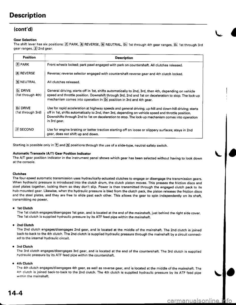
Gear Selection
The shift lever has six positions: E PARK. E REVERSE, N NEUTRAL, E 1st through 4th gear ranges, E 1st through 3rdgear ranges, @ 2nd gear.
Starting is possible only in E and E positions through the use of a slide-type, neutral-safety switch.
Automatic Transaxle (A/f, Gear Position Indicator
The Ay'T gear position indicator in the instrument panel shows which gear has been selected without having to look downat the console.
Clutch€s
The four-speed automatic transmission uses hydraulically-actuated clutches to engage or disengage the transmission gears.When hydraulic pressure is introduced into the clutch drum, the clutch piston moves. This presses the friction discs andsteel plates together, locking them so they don't slip. Power is then transmitted through the engaged clutch pack to itshub-mounted gear. Likewise, when the hydraulic pressure is bled from the clutch pack, the piston releases the friction discsand the steel plates, and they are free to slide past each other. This allows the gear to spin independently on its shaft,transmitting no power.
lst Clutch
The 1st clutch engages/disengages 1st gear, and is located at the end of the mainshaft, just behind the right sroe cover.The 1st clutch is supplied hydraulic pressure by its ATF feed pipe within the mainshaft.
2nd Clulch
The 2nd clutch engagegdisengages 2nd gear, and is located at the middle of the mainshaft. The 2nd clutch is joined
back-to-back to the 4th clutch. The 2nd clutch is supplied hydraulic pressure through the mainshaft by a circutr connect-ed to the internal hvdraulic circuit,
3rd Clutch
The 3rd clutch engages/disengages 3rd gear, and is located at the end of the countershaft. The 3rd clutch is suooliedhydraulic pressure by its ATF feed pipe within the countershaft.
ilth Clutch
The 4th clutch engages/disengages 4th gear, as well as reverse gear, and is located at the middle of the mainshaft. The4th clutch is joined back-to-back to the 2nd clutch. The 4th clutch is supplied hydraulic pressure by its ATF feed pipewith in the mainshaft.
\-a
PositionDe3cription
E PARK
E REVERSE
N NEUTRAL
E DRIVE
{1st through 4th)
Ei DRtvE('lst through 3rd)
B SECOND
Front wheels locked; park pawl engaged with pa* on countershaft. All clutches released.
Reverse; reverse selector engaged with countershaft reverse gear and 4th clutch locked.
All clutches released.
General driving; starts off in 1st, shifts automatically to 2nd, 3rd, then 4th, depending on vehiclespeed and throttle position. Downshift through 3rd, 2nd and 1st on deceleration to stop. The lock-upmechanism comes into operation in @ position in 3rd and 4th gear.
Use for rapid acceleration at highway speeds and general driving; up-hill and down,hill dfiving; stansotf in 1st, shifts automatically to 2nd, then 3rd, depending on vehicle speed and throttle position.
Downshifts through 2nd to lst on deceleration to stop. The lock-up mechanism comes into operationin 3rd gear,
Use for engine braking or better traction starting off on loose or slippery surfaces; stays in 2ndgear, does not shift up and down.
14-4
Page 711 of 2189
\
Lock-up System
Lock-up Clutch
1. Ooeration (clutch onl
with the lock-up clutch on, the fluid in the chamber between the torque converter cover and the lock-up piston is drained
off, and the converter fluid exerts pressure through the piston against the torque converter cover, As a result, the conven-
er turbine is locked to the convefter cover. The effect is to bypass the converter, thereby placing the vehicle in direct drive
LOCK.UP PISTONDAMPER SPRING
The power flows by way ot:
Engine
{
Drive plate
i
Torque converter cover
I
Lock-up piston
Damper spring
I
Turbine
Mainshaft
ODeration {clutch off}
With the lock-up clutch off, the fluid flows in the reverse of "clutch on." As a result, the lock-up piston moves away from
the converter cover, and the torque converter lock-up is releassd.
Engine
t
Drive plate
I
Torque convener cover
{
Pump
I
Turbine
Mainshaft
TOROUECOVER
(cont'd)
COI{VERTER
\
TURBNE
MAINSHAFT
14-33
Page 834 of 2189
Clutch
lllustrated Index (A4RA, B4RA Transmission)
3RD CLUTCH
O-RINGSBeplace. CLUTCH ptSTON
lST CLUTCH
CLUTCHDRUM
CLUTCH ENDPLATE
SPRING RETAINER
RETUNN SPRING
CLUTCH DRUM
SNAP RING
CLUTCH END
CLUTCH PLATESStandard thickness:1.6 mm (0.063 in)
SNAP RING
CHECK VALV€
\
14-156
Page 835 of 2189
SNAP RING
2NDi4TH CLUTCH
SNAP RING
SPRING RETAINER
RETURN SPRING
DISC SPRING
CHECK VALVE
O.RINGSReplace.4TH CLUTCH DRUM
CLUTCH PISTON
CLUTCH PLATESStandardthickness: O-RINGS2.0 mm {0.079 in) Replace.
SNAP RING
14-157
Page 836 of 2189
Clutch
lllustrated Index (M4RA Transmission)
3RD CLUTCHCLUTCHDRUM
CLUTCH PISTON
DISC SPRING
CLUTCII END
rST CLUTCH
CLUTCH E D
SI{AP RIiIG
CLUTCH PLATESStandard thickness:1.6 mm (0.063 in)
CHECK VALVE
L
14-158
Page 838 of 2189
Clutch
Disassembly
1.Remove the snap ring. then remove the clutch endplate, clutch discs and plates.
SCREWDRIVER
SNAP RING
2. Remove the disc spring.
NOTE: Except 2nd clutch.
1CLUTCI{ DRUM
DISC SPRING
L
14-160
3. Installthe special tools as shown.
CLUTCHCOMPRESSORAOLT ASSEMBLY07GAE - PG4tt200olO'GAE - FG4O2OA
CLUTCH SPRINGCOMPRESSORATTACHMENT07LAE -PX40,t 00
CLUTCH SPRINGCOMPRESSORATTACHMENT07LAE - PX()100o107HAE - P150100
CLUTCH SPRINGCOMPRESSORATTACIIMENToTLAE-PX40100
CLUTCH SPRINGCOMPRESSORATTACHMENT07LAE - Px/Ol00ot07HAE - PLs0100
CLUTCHCOMPRESSORBOLT ASSEMBLY07GAE - PG/O200
OTGAE - PG4O2OA
Page 842 of 2189
Glutch
Reassembly (cont'd)
7. Installthe snap ring.
Removs the special tools.
Install the disc spring.
NOTE: Install the disc spring in the direction
shown, except 2nd clutch.
SNAP RING
8.
o
14-164
h
10.
ll.
Soak the clutch discs thoroughly in ATF for a mini-
mum of 30 minutes.
Starting with a clutch plate, alternately install the
clutch plates and discs. Install the clutch end plate
with flat side toward the disc.
NOTE: Before installing the plates and discs, make
sure the inside of the clutch drum is free of din orother foreign mafter.
CLUTCH END PLATEInstall in this direcrion.
12. Installthe snap ring.
SCREWDRIVER
SNAP RING
Page 843 of 2189

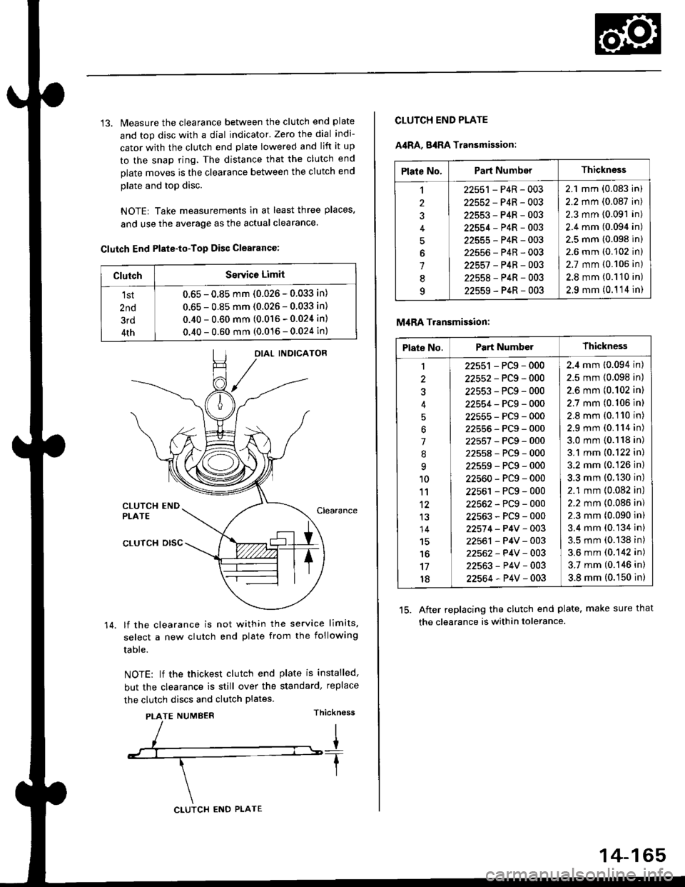
13. Measure the clearance between the clutch end plate
and top disc with a dial indicator' Zero the dial indi-
cator with the clutch end plate lowered and lift it up
to the snap ring. The distance that the clutch end
plate moves is the clearance between the clutch end
plate and top disc.
NOTE| Take measurements in at least three places,
and use the average as the actual clearance.
Clutch End Plste-to-Top Disc Clearance:
OIAL INDICATOR
CLUTCH ENDPLATEClearance
14.
CLUTCH DISC
lf the clearance is not within the service limits,
select a new clutch end plate from the following
table.
NOTE: lf the thickest clutch end plate is installed,
but the clearance is still over the standard, replace
the clutch discs and clutch plates.
PLATE NUMBERThickn6ss
ClutchSerYice Limit
1st
2nd
3rd
4th
0.65 - 0.85 mm (0.026 - 0.033 in)
0.65 - 0.85 mm (0.026 - 0.033 in)
0.40 - 0.60 mm (0.016 - 0.024 in)
0.40 - 0.60 mm (0.016 - 0.024 in)
CLUTCH ENO PLATE
14-165
Plate No.Part NumberThickness
,l
2
J
4
5
6
1
8q
22551 - P4R - 003
22552-P4R-003
22553-P4R-003
22554-P4R-003
22555-P4R-003
22556-P4R-003
22557 -P4B-OO3
22558-P4R-003
22559-P4R-003
2.1 mm (0.083 in)
2.2 mm (0.087 in)
2.3 mm (0.091 in)
2.4 mm (0.094 in)
2.5 mm (0.098 in)
2.6 mm (0.102 in)
2.7 mm {0.106 in)
2.8 mm {0.110 in)
2,9 mm (0.1 '14 in)
CLUTCH END PLATE
A4RA, g4RA Transmission:
M,IRA Transmi$ion:
15. After replacing the clutch end plate. make sure that
the clearance is within tolerance.
Plate No.Part NumberThickness
1
3
'l
.'q
10
11't2
13
14
15'16
17
18
22551 - PCg - 000
22552-PCg-000
22553-PCg-000
22554-PCg-000
22555-PCg-000
22555-PCg-000
22557-PCg-000
22558-PCg-000
22559-PCg-000
22560-PCg-000
22561 - PCg - 000
22562-PCg-000
22563-PCg-000
22574 - P4V - 003
22561 - P4V - 003
22562- P4V - 003
22563-P4V-003
22564-P4V-003
2.4 mm (0.094 in)
2.5 mm (0.098 in)
2.6 mm {0.102 in)
2.7 mm (0.106 in)
2.8 mm (0.110 in)
2.9 mm (0.114 in)
3.0 mm {0.118 in)
3.1 mm (0.122 in)
3.2 mm (0.126 in)
3.3 mm (0.130 in)
2.1 mm (0.082 in)
2.2 mm {0.086 in)
2.3 mm (0.090 in)
3.4 mm (0.134 in)
3.5 mm (0.138 in)
3.6 mm (0.142 in)
3.7 mm (0.146 in)
3.8 mm (0.150 in)