Page 1003 of 2189
Forward Clutch
Reassembly {cont'd)
9. Install the disc spring.
NOTE: Installthe disc spring in the direction shown.
- "arr"" o"u*
11.
Soak the clutch discs thoroughly in CW Fluid for a
minimum of 30 minutes.
Starting with a clutch plate. alternately install the
clutch plates and discs. Install the clutch end plate
with flat side toward the disc.
NOTE: Before installing the plates and discs, make
sure the inside of the clutch drum is free of dirt or
other toreign matter.
CLUTCH END PLATEInstall in this dir€ction.
10.
DISC SPRING
14-326
12. Installthe snap ring.
13. Verify that the snap ring end gap is correct.
SNAP RING
CLUTCH
Minimum 7.9 mm (0.31 ini
Page 1004 of 2189

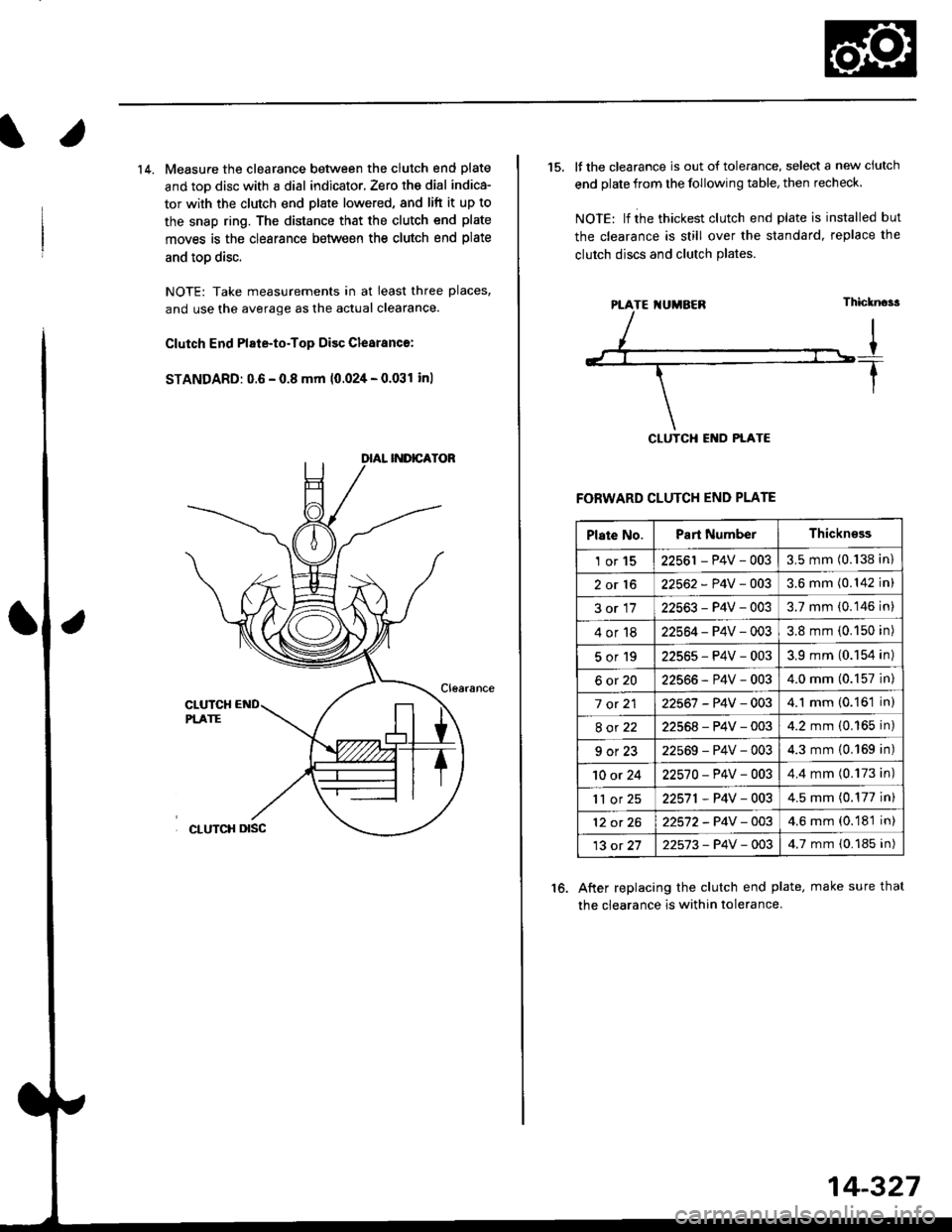
14. Measure the clearance between the clutch end plate
and toD disc with a dial indicator, Zero th€ dial indica-
tor with the clutch end plate lowered, and lift it up to
the snap ring. The distance that the clutch end plate
moves is the clearance between the clutch end plate
and toD disc.
NOTE: Take measurements in at least three places,
and use the average as the actual clearance.
Clutch End Plate-to-Top Disc Clesranc€:
STANDARD: 0.6 - 0.8 mm 10.024 - 0.031 inl
15. It the clearance is out of tolerance, select a new ciutch
end plate from the following table, then recheck.
NOIE: lf ihe thickest clutch end plate is installed but
the clearance is still over the standard, replace the
clutch discs and clutch Plates.
FORWARD CLUTCH END PLATE
After replacing the clutch end plate, make sure thal
the clearance is within tolerance.
16.
PTATE I{UMBEN
Plate No.Part NumberThickn€ss
1or1522561 - P4V - 0033.5 mm (0.138 in)
2or1622562 - P4V -OO33.6 mm (0.142 in)
3or1722563-P4V-0033.7 mm (0.146 in)
4or1822564 - P4V - 0033.8 mm (0.150 in)
5or192256s-P4V-0033.9 mm (0.154 in)
6ot2022566-P4V-0034.0 mm (0.157 in)
7 ot 2122567 -P4V -0034.1 mm (0.161 in)
8ot2222568-P4V-0034.2 mm (0.165 in)
9ot2322569-P4V-0034.3 mm {0.169 in)
10 or 2422570-P4V -OO34.4 mm (0.173 in)
'll or 2522571,P4V-0034.5 mm (0.177 in)
12 ot 2622572-P4V-OO34.6 mm (0.181 in)
13 ot 2722573-P4V -OO34.7 mm {0.185 in)
14-327
Page 1014 of 2189

Transmission
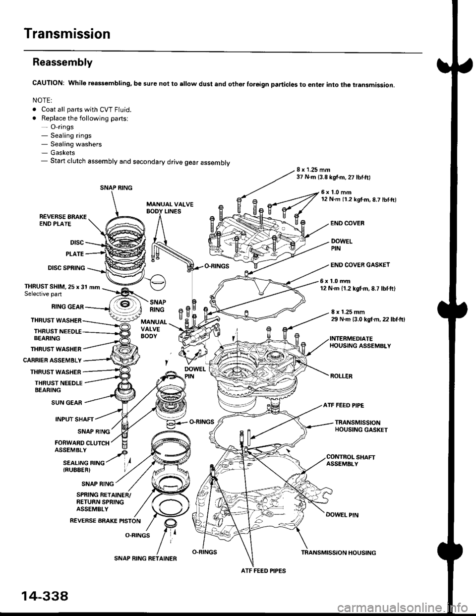
Reassembly
CAUTION: While reassembling. be sure not to sllow dust and othor foreign particles to enter into the transmission.
NOTE:
. Coat all parts with CVT Fluid.
. Replace the following parts:- O-rings- Sealing rings- Sealing washers- Gaskets- Start clutch assembly and secondary drive gear assembly8 x 1.25 mm37 N.m {3.8 kgf.m,27 lbtftl
MANUAL VALVE
6x1.0mm12 N m 11.2 kgf.m,8.7 lbl.ft)
LINESREVERSE BRAKEEND PLATE
Dtsc
PLATE
DISC SPRING
THRUST WASHER
CARRIER ASSEMBLY
THRUST WASHER
THRUST NEEDLEBEARING
END COVEB
DOWELPIN
END COVER GASKET
6x1.0mm12 N.m 11.2 kgtm,8.7 lbtft)THRUST SHIM,25 x 31 mmSelective part
RING GEAR
THRUST WASHER
THRUSTBEARING
8 x 1.25 mm29 N.m 13.0 kgl m, 22 lbtftl
INTERMEDIATEHOUSING ASSEMBLY
ROLI.IR
SNAPRINGeBH^cMANUALVALVEBOOY
SUN GEAR
INPUT SHAFT
(RUBEERI
ATF FEED PIPE
O-RINGSTRANSMISSIONHOUSING GASKETSNAP RING
FORWARD CLUTCH
SNAP RING
SHAFTASSEMALY
DOWEL PtN
SPRING RETAINER/RETURN SPRINGASSEMBLY
REVERSE BRAKE PISTON
O.RINGS
SNAP RING
ATF FEED PIPES
14-338
SNAP RING RETAINERTRANSMISSION HOUSING
Page 1016 of 2189

Transmission
16.
Reassembly (cont'dl
21.
17.
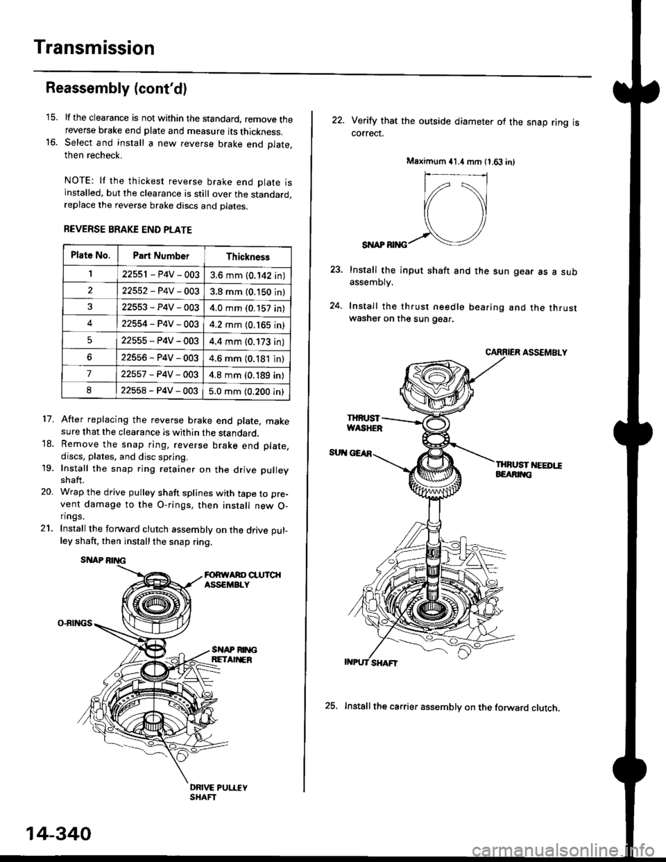
lf the clearance is not within the standard, remove thereverse brake end plate and measure its thickness.Select and install a new reverse brake end Dlate.then recheck.
NOTE: lf the thickest reverse brake end olate isinstalled, but the clearance is still over the standard,replace the reverse brake discs and plates.
REVERSE BRAKE END PLATE
After replacing the reverse brake end plate, makesure that the clearance is within the standard.Remove the snap ring, reverse brake end plate,
discs, plates. and disc spring.
Install the snap ring retainer on the drive pulley
shaft.
Wrap the drive pulley shaft splines with tape to pre-
vent damage to the O-rings, then install new O-n ngs.
Install the forward clutch assembly on the drive pul-
ley shaft, then installthe snap ring.
SITAP
O-RINGS
18.
19.
20.
SI{AP RIM;BETA EB
DRIVE PUI.IEYSHAFT
Plat6 No.Part NumberThickness
122551 - P4V - 0033.6 mm (0.142 in)
22552-P4V-0033.8 mm (0.150 in)
22553-P4V-0034.0 mm (0.157 in)
422554-P4V-0034.2 mm (0.165 in)
522555-P4V-0034.4 mm (0.173 in)
622556-P4V-0034.6 mm (0.181 in)
722557 -P4V -OO34.8 mm (0.189 in)
822558-P4V-0035.0 mm (0.200 in)
14-340
25. Installthe carrier assembly on the forward clutch.
22. Verity that the outside diameter ol the snap ring iscorrect.
SI{AP RIiIG
Install the input shaft and the sun gear as a subassemDry.
Install the th.ust needle bearing and the thrustwasher on the sun gear.
CARRIER ASSEMBLY
THFUST I'IEEDI!EEARIT{G
Msximum 41.4 mm 11.63 in)
IHruST
Page 1457 of 2189

Clutch InsPection
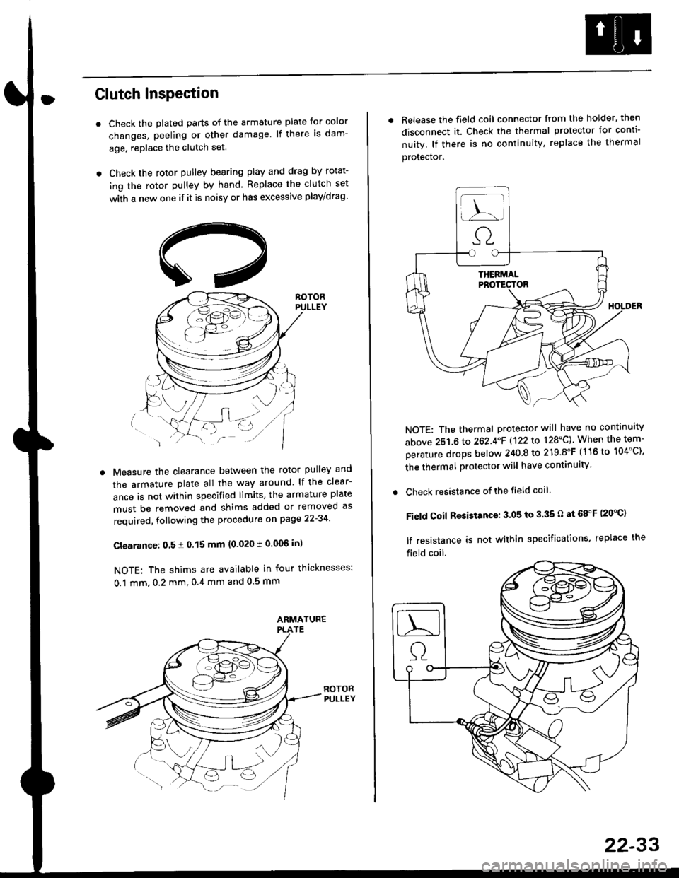
Check the plated parts of the armature plate for color
changes, peeling or other damage lf there is dam-
age. replace the clutch set.
Check the rotor pulley bearing play and drag by rotat-
ing the rotor pulley by hand Replace the clutch set
with a new one if it is noisy or has excessive play/drag
Measure the clearance between the rotor pulley and
the armature plate all the way around lf the clear-
ance is not within specified limits, the armature plate
must be removed and shims added or removed as
required, following the procedure on page 22-34
Cl€arance: 0.5 ! 0.15 mm {0.020 t 0.006 in)
NOTE: The shims are available in four thicknesses:
0.1 mm,0.2 mm,0.4 mm and 0.5 mm
. Release the field coil connector from the holder' then
disconnect it. Check the thermal protector for conti-
nuity. lf there is no continuity. replace the thermal
protecror,
NOTE: The thermal protector will have no continuity
above 251.6 to 262.4oF 1122lo 128'C). When the tem-
perature drops below 240 8 to 219.8"F (116 to 104"C),
the thermal protector will have continuity
. Check resistance of the field coil
Field Coil Resistance: 3.05 to 3.35 O at 68"F (20"C)
lf resistance is not within specifications, replace the
field coil.
22-33
Page 1458 of 2189
Compressor {SANDEN)
Clutch Overhaul
1. Remove the center nut while holding the armatureplate with the tool.
CENTER NUT17.6 N.m {1.8 kg{.m,'t3 tbnft}
2. Remove the armature plate by pulling it up by hand.
ARMATURE PLATE
A/C CLUTCH HOLDER{Commerciallv aveilable)Robinair: P/N 10204Kent-Moore: P/N J37872
22-34
3. Remove snap ring B with snap ring pliers.
NOTE:
. Be careful not to damage the rotor pulley and
compressor during removal/installation.. Once snap ring B is removed, replace it with anew one.
A
\/
G::.
Remove the rotor pulley from the shaft with a puller
and the special tool.
NOTE: Place the claws of the puller on the back of
the rotor pulley, not on the belt area; otherwise the
rotor pulley can be damaged.
. r \:g2rl -/ /
.-!L;j'/
TWO JAW PULLER{Commercially
Page 1464 of 2189
Compressor (DENSOI
Clutch Inspection
Check the plated parts of the pressure plate for colo.changes, peeling or other damage. lf there is dam-age, replace the clutch set.
Check the pulley bearing play and drag by rotatingthe pulley by hand, Replace the clutch set with a newone if it is noisy or has excessive play/drag.
Measure the clearance between the pullev and thepressure plate all the way around. lf the clearance isnot within specified limits, the pressure plate must beremoved and shim(s) added or removed as required,
following the procedure on page 22-41.
Clearanca:0.5 t 0.15 mm {0.020 r 0.006 in}
NOTE: The shims are availabte in three thicknesses:0.1 mm,0.3 mm and 0.5 mm.
22-40
. Check resistance of the field coil. lf resistance is notwithin specifications, replace the field coil.
Fiald Coil Resistanc€: 3.it to 3.8 O at 20.C l68.Fl
Page 1465 of 2189
Clutch Overhaul
1. Remove the center bolt while holding the pressure
olate with the sPecialtool.
CENTER BOLT13.2 N.m (1.35 ksl m, 9.?6 lbf'ft)
A/C CLUTCH HOLOER(Commercially available)
Robinair: P/N 10204
Kent-Moore: P/N J37872
Remove the pressure plate and shim(s). taking care
not to lose the shim{sl.
PAESSUREPLATE
3. Remove the snap ring B with snap ring pliers, then
remove the pulley Be careful not to damage the
pulley and comPressor'
SNAP RING B
Replace.
'.L-)
.'l 5$ f-t
1/---( ll l,
vll/
(cont'd)
22-41