1999 HONDA CIVIC ac system
[x] Cancel search: ac systemPage 1177 of 2189
Brake Booster InsPection
FunctionalTest
1. With the engine stopped, depress the brake pedal
several times to deplete the vacuum reservoir, then
depress the pedal hard and hold it for 15 seconds lf
the pedal sinks' either the master cYlinder is
bypassing internally, or the brake system (master
cylinder. lines. modulator, proportioning control
valve, or caliPer) is ieaking.
2. Start the engine with the pedal depressed lf the
pedal sinks slightly, the vacuum booster is operating
normally. lf the pedal height does not vary, the
booster or check valve is faultY.
3. With the engine running. depress the brake pedal
lightly. Apply just enough pressure to hold back
automatic transmission creep. lf the brake pedal
sinks more than 25 mm (1.0 in.) in three minutes,
the master cvlinder is faulty. A slight change in
pedal height when the A'lC compressor cycles on
and off if normal. (The A/C compressor load
changes the vacuum available to the booster')
Leak Test
1. Depress the brake pedal with the engine running.
then stop the engine. lf the pedal height does not
vary while depressed for 30 seconds, the vacuum
booster is OK. lf the pedal rises. the booster is
faulty.
2, With the engine stopped, depress the brake pedal
several times using normal pressure When the
Dedal is first depressed, it should be low On con-
secutive applications, the pedal height should grad-
uallv rise. lf the pedal position does not vary, checK
the booster check valve.
l./
19-23
Booster Check Valve Test
1. Disconnect the brake booster vacuum hose at the
booster.
2. Stan the engine and let it idle. There should be vac-
uum. lf no vacuum is available, the check valve is
not working properly. Replace the brake booster
vacuum hose and check valve, and retest.
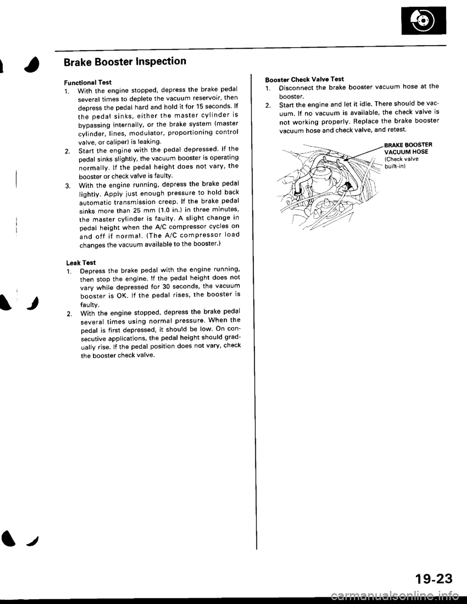
BRAKE BOOSTERVACUUM HOSE(Check valve
built-in)
Page 1185 of 2189
IReassembly
HP* "n ",, hos6 or drv brush to ctoan brake assemblies.
o Use an OSHA-approved vacuum cleanel to avoid brealhing brake dust'
. Contaminated brake discs or pads reduce stopping sbility.
. When reusing the pads, in3tall thom in thoil original positions to prevent loss of braking efficiency'
CAUTION:
. Do not soill brake fluid on the vehicle; lt may damage lhe paint; if brake fluid does contacl the paint' wash it oft imme-
diately with water.
. Cl€an all Darts in brake fluid and air dry; blow out all passagss with comPressed air'
. Belore rsas3embling, check that all parts ars free ot du3t and othor tor€ign particles'
. Replace parts with new ones whenever spscifiod to do so.
o Make sur€ no dirt or othor foreign matter is allowed to contaminate the brake tluid'
. Always use Genuine Honda DOT 3 Brake fluid. Using a non-Honda brake fluid can Gtuse corrosion and decrease the
lif€ of ths system.
NOTE:
. Coat piston, piston seal, and caliper bore with clean brake fluid
. Replace all rubber parts with new ones whenever disassembled.
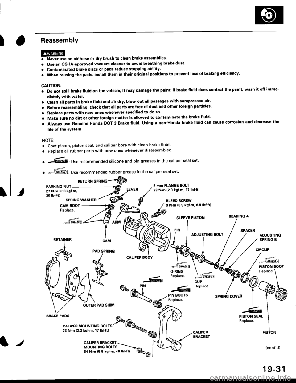
o .-'{@]: Use recommended silicone and pin greases in the caliper seal set.
. -ffi,Use recommended rubber grease in the caliper seal set.
RETuRN sPRTNG -"'9
8 mm FLANGE BOLT23 N.m (2.3 kgt'm, 17 lbf ftl
BLEED SCREW
@
9 N.m (0.9 kgtm,6.5lbf'ft|
CUP
=^.
PISTON BOOT
(cont'd)
19-31
BEARING A
PAO SPNING
F
\
OUTER PAD SHIM
r--- Replace..ffiPIN BOOTSReplace.
-61
@@-t-.
"l-r,r., "or"'*o " orr" I @.,23 N.m {2.3 kgtm, 17lbf.ftl \@
PISTON SEALReplace.
CALIPEBBRACKET
iiilji:ll;;
__X.,,..".^
BRAKE PAOS
PISTON
l/CALIPER BMCKET \MOUNTINGEOLTS ----.-,o,
54 N.m (5.5 kgf.m, 40lbl.ft) q%
Page 1192 of 2189
Rear Drum Brake
Brake Shoe Reassembly {cont'dl
Connect the parking brake cable to the parking
brake lever.
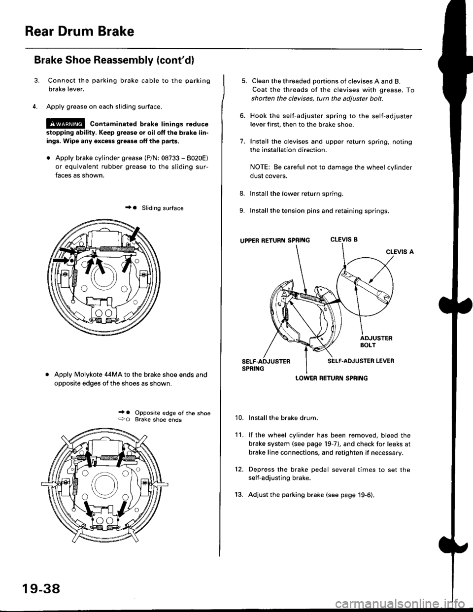
Apply grease on each sliding surface.
!@ contaminated brake linings reduce
stopping ability. Keep grease or oil off the blake lin-
ings. Wipe any excess grease off the parts,
. Apply brake cylinder grease {P/N: 08733 - 8020E)
or equivalent rubber grease to the sliding sur-
faces as shown.
+a Sliding surlace
Apply Molykote 44MA to the brake shoe ends and
opposite edges ofthe shoes as shown.
_' o Opposite edge of the shoe+O Brake shoe ends
19-38
13.
5. Clean the threaded portions of clevises A and B.
Coat the threads of the clevises with grease. To
shoften the clevises, tun the adjuster bolt.
6. Hook the self-adjuster spring to the self-adjuster
lever first, then to the brake shoe
7. Install the clevises and upper return spring. noting
the installation direction.
NOTE: Be careful not to damage the wheel cylinder
dust covers,
8. Install the lower return spring.
9. Install the tension pins and retaining springs.
uppER RETURT{ SpRtNG CLEVIS B
CLEVIS A
Installthe brake drum.
lf the wheel cylinder has been removed, bleed the
brake system (see page 19-7), and check for leaks at
brake line connections, and retighten if necessary.
Depress the brake pedal several times to set the
self-adjusting brake.
Adjust the parking brake (see page 19-6).
't0.
11.
12.
LOWER RETURN SPRING
Page 1196 of 2189
L-
t
Anti-lock Brake System (ABSI
Special Tools ............. 19-44
Component Locations ......................... 19-45
Anti-lock Brake System (ABS)
Features/Construction ..................., 19-46
Operation ............... 19-47
Circuit Diagram ......... 19-50
ABS Control Unit Terminal
Arrangement ......... 19-52
Troubleshooting Precautions ............. 19-54
Diagnostic Trouble Code (DTCI
Diagnostic Trouble Gode (DTCI
Indication ........... 19-56
DTC Erasure ........... 19-57
Symptom-to System Chart ............. 19-58
Troubleshooting
ABS Indicator Light Does Not
Come On ............ 19-60
ABS Indicator Light Does Not
Go Off ............................................ 19-62
Wheel Sensor ........ 19-64
Solenoid ................. 19-60
ABS Pump Motor ............................. 19-68
Main Relay ............. 19-71
lgnition Voltage .... 19-73
Central Processing Unit {CPU} ........ 19-74
Modulator Unit
Removal/lnstallation ....................... 19-75
ABS Control Unit
Replacement ......... 19-76
Pulsers/Wheel Sensors
Inspection .............. 19-76
Wheel Sensor Replacement ............ 19-77
t/
Page 1199 of 2189
Anti-lock Brake System (ABSI
Featu res/Construction
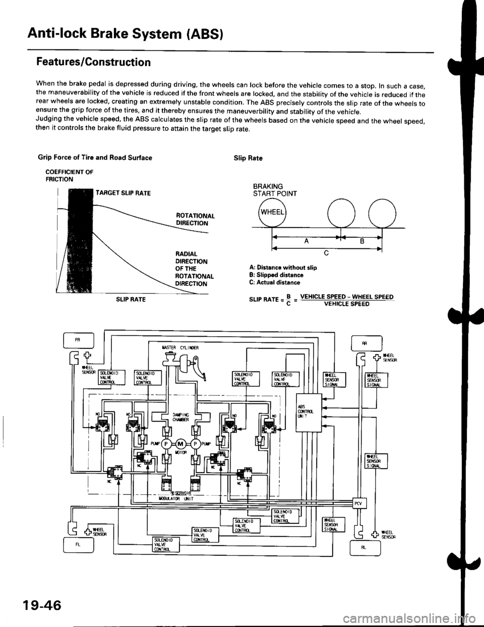
When the brake pedal is depressed during driving, the wheels can lock before the vehicle comes to a stop, In such a case,the maneuverability of the vehicle is reduced if the front wheels are locked, and the stability of the vehicle is reduced if therear wheels are locked, creating an extremely unstable condition. The ABS precisely controls the slip rate of the wheels toensure the grip force of the tires. and it thereby ensures the maneuverbility and stability of the vehicle.Judging the vehicle speed. the ABS calculates the slip rate of the wheels based on the vehicle speed and the wheel speed,then it controls the brake fluid pressure to attain the target slip rate.
Grip Force of Tire and Road Surlace
COEFFICIENT OFFRICTION
TARGET SLIP RATE
Slip Rate
BRAKINGSTART POINT
ROTATIONALDIRECTION
RADIALDIRECTIONOF THEROTATIONALOIRECTION
A: Distance without slio8: Slippsd distanceC: Actuel distance
sr-rrmre=f=SLIP RATEVEIIICLE SPEED - WHEEL SPEEOVEHICLE SPEED
19-46
Page 1200 of 2189
t-Operation
t
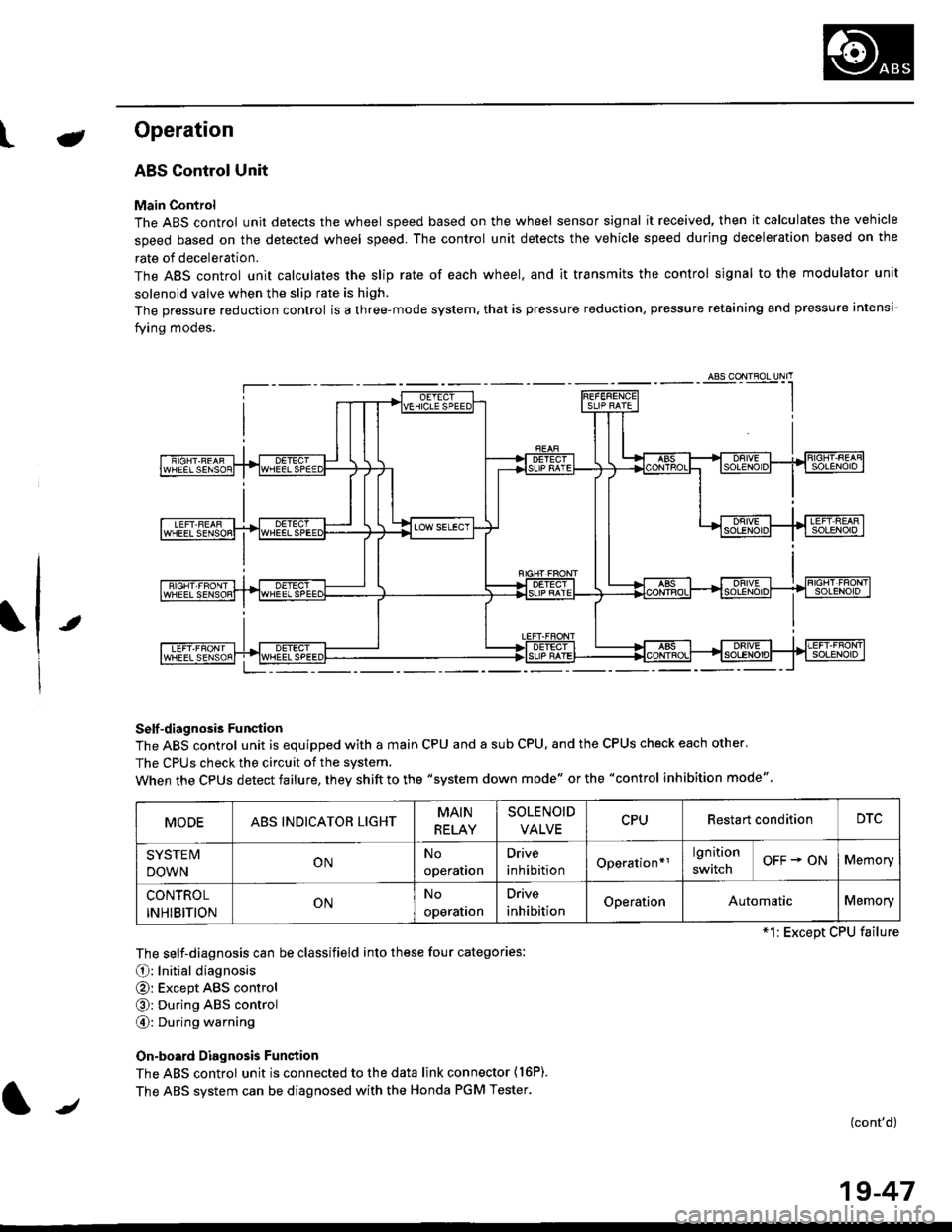
ABS Control Unit
Main Control
The ABS control unit detects the wheel speed based on the wheel sensor signal it received, then it calculates the vehicle
speed based on the detected wheel speed. The control unit detects the vehicle speed during deceleration based on the
rate of deceleration.
The ABS control unit calculates the slip rate of each wheel. and it transmits the control signal to the modulator unit
solenoid valve when the slip rate is high.
The pressure reduction control is a three-mode system, that is pressure reduction, pressure retaining and pressure intensi-
fying modes.
Self -diagnosis Funqtion
The ABS control unit is equipped with a main CPU and a sub CPU, and the CPUS check each other'
The CPUs check the circuit of the svstem.
When the CPUS detect failure, they shift to the "system down mode" or the "control inhibition mode"
The self-diagnosis can be classifield into these four categories:
O: Initial diagnosis
@: Except ABS control
@: During ABS control
@: During warning
On-board Diagnosis Funstion
The ABS control unit is connected to the data link connector {16P).
The ABS system can be diagnosed with the Honda PGM Tester.
(cont'd)
MODEABS INDICATOR LIGHTMAIN
RELAY
SOLENOID
VALVECPURestart conditionDTC
SYSTE IV
DOWNONNo
operation
Drive
inhibitionOperation*rlgnition
switchOFF + ONMemory
CONTROL
INHIBITIONONNo
operalron
Drive
inhibitionOperationAutomaticMemory
*1: Except CPU failure
/
19-47
Page 1201 of 2189
Anti-lock Brake System {ABS)
Operation (cont'dl
ABS Modulator
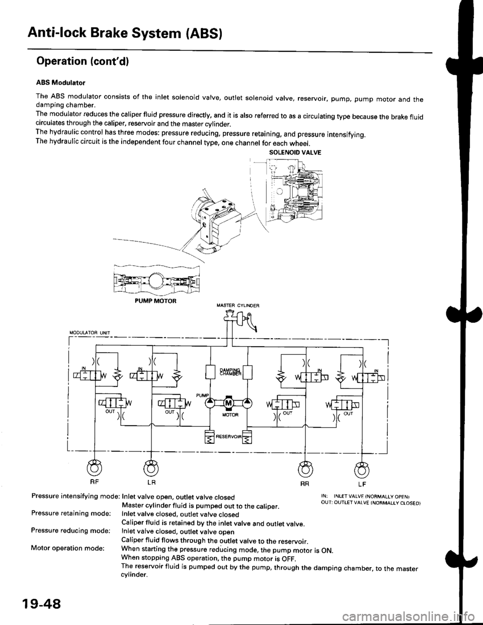
The ABS modulator consists of the inlet solenoid valve, outlet solenoid valve, reservoir, pump, pump motor and thedamping chamber.
The modulator reduces the caliper fluid pressure directly, and it is also referred to as a circulating type because the brake fluidcirculates through the caliper, reservoir and the master cylinder.The hydraulic control has three modes: pressure reducing, pressure retaining, and pressure intensifying.The hydraulic circuit is the independent four channel type, one channel for each wheel.
RF LR
Pressure intensifying mode: Inlet valve open, outlet valve closed
Pressure retaining mode:
Pressure reducing mode:
Motor operation mode:
rN: INLETVALVE {NORMALtY OpENIOUT: OUTIET VALVE {NORMALIY CTOSED)Master cylinder fluid is pumped out to the caliDer.Inlet valve closed, outlet valve closedCaliper fluid is retained by the inlet valve and outlet valve.Inlet valve closed, outlet valve oDenCaliper fluid flows through the outlet valve to the reservoir.When starting the pressure reducing mode, the pump motor is ON.When stopping ABS operation, the pump motor is OFF.The reservoir fluid is pumped out by the pump, through the damping chamber, to the mastercvlinder.
PUMP MOTOR
19-48
Page 1205 of 2189
ABS Control Unit Terminal Arrangement
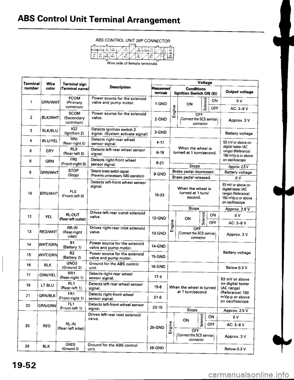
ABS CONTROL UNIT 26P CONNECTOR
Wire side of temale terminals
Terminalnumo0rWirecolorTerminal signTerminalnamoDgscriptionVoltage
Conditions(lgnition Switch ON flt))Output voltagoteminals
PCOM(Primary
common)
Power source for the solenoidvalve and pump motor.1-GNDON
=ONOV
AC: 3-6 V
BLK/WHTscoM(Secondary
common)
Power source for the solenoid
2.GNDOFF
lConnect the SCS service\
conneclor lApprox. 3 V
ELVBLUtG2(lgnition 2)Detects ignition switch 2
!9nal. (system activate signal)3-GNDBatt€ry voltage
BLU/YELRRO(Rear-right 0)Detects right-rear wheelsensor signal.4-17
When the wheel isturned at 1 turn/second.
53 mV or above ondigitaltester (ACra nge) {Fefera nce)150 mvp-p or aboveon oscilloscope
6GRYRLO(Rear-left 0)Detects left-rear wheel sensorsrgnal.6-19
8GRNFRO(Front-right 0)D€tects right-front wheelsgnsor srgnal,a-21StopsApprox.2.5VSTOP(Stop)hects brake switch signal.(Prevents unnecess€ry ABS operation)9-GNDBrake pedal depressed.Battery voltage
Brake pedal released.OV
10BRN^/vHTFLO(Front-left 0)
Detects left-front wheel sensorsignal.
10-23
When the wheel isturned at 1 turn/secono.
53 mV or above ondigitaltester (ACrange) (Referance)
150 mVFporaboveon oscilloscope
9!opsApprox. 2.5 V
12YELRLOUT(Rearjeft outlet)
Drives left-rear outlet solenoid
12.GNDON-9ONOV
OFFAC: 3^6 V
REDMHTRR]N(Rear-right
inlet)
Drives right-rear inlet solenoidvalve.13-GNDOFF
lconnect the SCS service]i connector IApprox. 3 V
14B1(Battery 1)Power source for the solenoidvatve and pump motor.14.GND
Battery voltage15WHT/G R N82(Baftery 2)Power source for the solenoidvarve ano pump motor.15.GND
r6BLKGND2{Ground 2)Ground for the ABS controlunit.16-GNDBelow 0.3 V
17GRN/'/ELRR1(Rear-right 1)Detects right-rear wheelsensor signal.17-4
When the wheel is turnedat 1 turn/second.
53 mV or aboveon digitaltester(AC range)(Referance) 150mVp-p or aboveon oscilloscope
19LT BLURLl(Rea.-left 1)Detects left-rear wheel sensorsagnal.19-6
GRN/BLKFRl(Front-right 1)Detects right-front wheelsensor signal.21-8
FL1(Front-left 1)Detects left-front wheel sensorsignal.23-10StopsApprox. 2.5 V
REDRL-IN(Rear-lett inletl
Drives left-r€ar inlet solenoid
25.GND
ut
ON
'6
-9ONOV
OFFAC: 3-6 V
OFF
lconnect the SCS service] connector lApprox. 3 V
BLKGND3(Ground 3)Ground for the ABS cgntrolunit.26.GNDBelow 0.3 V
19-52