Page 1207 of 2189
Troubleshooting Precautions
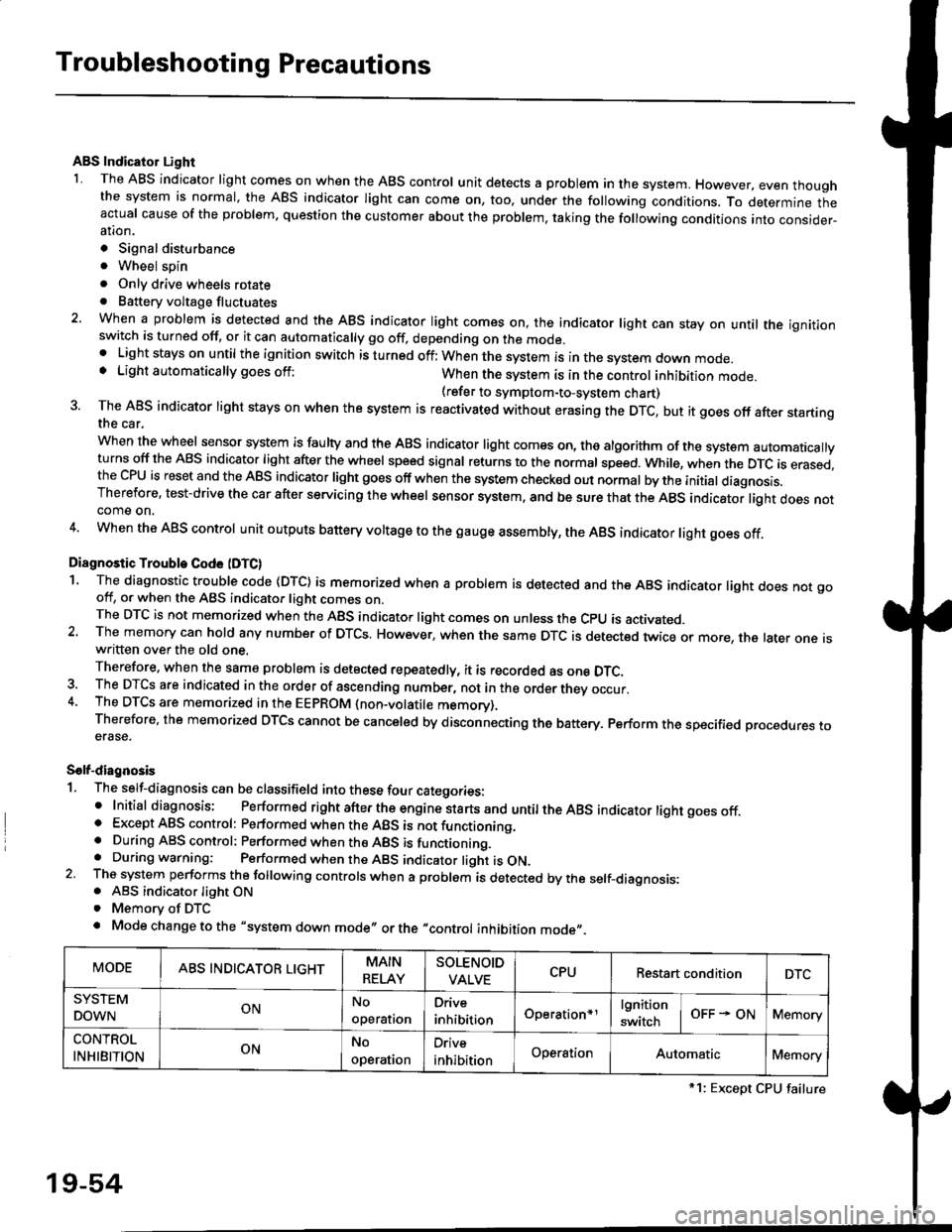
ABS Indicator Light
I The ABS indicator light comes on when the ABS control unit detects a problem in the system. However, even thoughthe system is normal, the ABs indicator light can come on, too, under the following conditions. To determine theactual cause of the problem, question the customer about the problem, taking the following conditions into consider-ation.
. Signal disturbance
. Wheel soin
. Only drive wheels rotate. Battery voltage fluctuates
2. When a problem is detected and the ABS indicator light comes on, the indicator light can stay on untat the ignitionswitch is turned off, or it can automatically go off, depending on the mode.. Lightstayson until the ignition switch isturned off;When the system is inthesvstem down mode.o Light automatically goes off:When the system is in the control inhibition mode.(refer to symptom-to-system chart)3 The ABS indicator light stays on when the system is reactivated without erasing the DTC, but it goes off after startingthe car.
when the wheel sensor system is faulty and the ABS indicator light comes on, the algorithm of the system automaticallyturns off the ABS indicator light after the wheel speed signal returns to the normal speed. while, when the DTC is erased,the CPU is reset and the ABS indicator light goes off when the system check€d out normal by the initial diagnosis.Therefore, test-drive the car after servicing the wheel sensor system, and be sure that the ABS indicator light does notcome on.
4. When the ABS control unit outputs battery voltage to the gauge assembty, the ABS indicator light goes off.
Diagnostic Trouble Code (DTC)
1. The diagnostic trouble code (DTC) is memorized when a problem is detected and the ABS indicator light does not gooff, or when the ABS indicator light comes on.The DTC is not memorized when the ABs indicator right comes on unress the cpU is activated.2. The memory can hold any number of DTCs. However, when the same DTc is detected twice or more, the later one iswritten over the old one.
Therefore. when the same problem is detected repeatedly, it is recorded as one DTC.3. The DTCS are indicated in the order of ascending number, not in the order thev occur.4. The DTCS are memorized in the EEpROM {non-volatile memorv}.Therefore, the memorized DTCS cannot be canceled by disconnecting the battery. perform the specified orocedures toerase.
Solf-diagnosis
1. The self-diagnosis can be classifield into these four categories:' Initial diagnosis; Performed right after the engine sta rts and untiltheABs indicator light goes off.o Except ABS control: Performed when the ABS is not functioning,. During ABS control: Performed when the ABS is functioning.. During warning: Performed when the ABS indicator light is ON.2 The system performs the following controls when a problem is detected by the self-diagnosis:. ABS indicator light ON. Memory of DTC
. Mode change to the "system down mode,, or the "control inhibition mode,,.
MODEABS INDICATOR LIGHTMAIN
RELAY
SOLENOID
VALVECPURestart conditionDTC
SYSTEM
DOWNONNo
operal|on
Drive
inhibitionOperation+rlgnition
switchOFF - ONMemory
CONTROL
INHIBITIONONNo
operat|on
Orive
inhibitionOperationAutomaticMemory
*1: Except CPU failure
19-54
Page 1211 of 2189
Diagnostic Trouble Code (DTCI
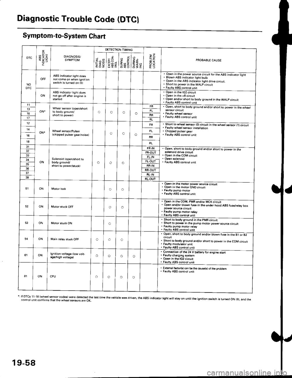
Symptom-to-System Chart
DTC
oH1=DIAGNOSIS/SYMPTOM
DETECTION TIMING
>=PNOBABLE CAUSEi.'sEV98€E
zr\9=6<_6
=t
6tz
NODTC
ABS indicator iighr doesnot com€ on when ignirionswrt.h is lu.ned on (ll)
, Open in the pow€. source circ!ir ror the ABS -.ndicato;l isht. Elown ABS indicalo.lighr butb' Open in rhe ABS indicaror tight drive cncuit.. Shori ro pow€r in theWALpcircuit. FaultyABS contrct!nit
ONABS indicator light doesnol90 oft 6frer engine isOpen in the lG2 circuitOpon in the +B circuirOp€n andlor short ro body ground jn the WALP circuitFaultv AAS coni.ol unnt1
oN.Wheel sensor (op€n/shortOooo13upen, snofiro bodyground and/or shodro power in rhe wh€61
Faulty ABS co.lrctunitllBL12
oN.(chipp€d pulser gea/noise)oao
Short to wh6sls€n6or (O)circuir in t'e.h;;Go-nso, trtcircutiFaulty whsel s€nsor insra|ation
Faulty ABS cont.olunir
I8
31
ONSolenoid (open/shon roaoa
Op.ni shon to bodyground and/o. shorrto powsr in rhe
op€n in lh6 coM circuit
Faulty ABS conlrclunit
32F8-OUTFL.IN3'lFT.OUTRF.IN88 OUT318t rN38RLOUT
ONoo
op€n in tho motor pow€..ourco circliaOp€n inih€ moro.cNOcircuit
Faulty ABS conrrol unit
52ONoo
Open in rh€ COM, PMR 6nd/o. MCKcircuirOp€n.n.Vor blown lus€ in the under hood AgS rusdretry box
Faufty pump moto. rotayfaulv ABS conlrolunit
53ONo
. Sho.tto bodygrou.d in the pMR circuit. Shon to powsr in tha puhp moror pow6rsource circu. r.urty pump motor.etay, FalltyABS contolunit
54ONooc
Open, rhorr ro bodygrcund and/or blown fus€ in the B1 or 82
Shonto body ground.n.Vor short to powor in rhe COM circuitFaulty modul.tor unnFaulty ABS controt unit
ONlgnition voltage (low vott-oooo
. Connection ot the24 V bariorv tor enqins starr. Faurtycharoins system. Op€n in th6lG2 circuit. Fa!lly ABS contrcl unil
81ONCPUoooo
E {€rml facior{sl en bs rhe ouse{sl ot |he probtemF.ulty ABS conrrot unit
r: It DTcs 1 1 18 {wheel sensor codes) wore del*ted the lasr time the v6h cls wEs d riv€n, rhe a8s indicator tight wi
stay on u ntit lh6 ignition swirch is rurn6d oN t), and theconnorunit contnms rhat rhe wheet sensoB . rc OK,
19-58
Page 1213 of 2189
Troubleshooting
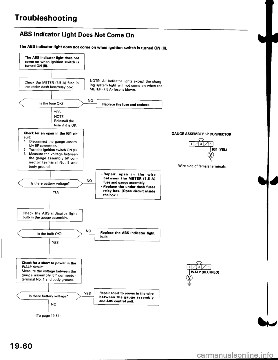
ABS Indicator Light Does Not Come On
YES
NOTE:Reinstallthefuse if it is OK.
The A8S indicator light does not come on when ignition switch is turned ON ll.
NOTE: All indicator tights except the charg,ing system light will not come on when theMETER 17.5 A) ft se is btown.
NO
GAUGE ASSEMBI"Y 5P CONNECTOR
Wire side of female terminals
Tho ABS indicator light does notcome on wh€n ignition switch istu.ned ON {lll.
check the METEB (7.5 A) fuse inthe under-dash fuse/relay box.
Beplace the tu3e and recheck.
Check for an open in th6 lcl cir-cuii:1, Disconnect the gauge assembly 5P connector.2. Turn the ignitjon switch ON l).3. Measure the voltage betweenthe gauge assembly 5P con-nector terminal No. 5 andbody ground.
. Ropair opan in tho wirobotwe€n thc METER t7.5 Attuso and gauge .$cmbly.. Roplacc th. und.r-dash tus./r.l.y box. lop.r cirouit in3idothe box.l
ls there baftery voltage?
Check the ABS indicator lightbulb in the gauge assembly.
ls the bulb OK?
Ch€ck tor a short to power in theWALP circuit:Measure the voltage between thegauge assembly 5P connectorterminal No. I and body ground.
Replir short to power in tho wiiGb.tweon the gruge rs3embly.nd ABS control unh.
ls there battery voltage?
lTo page 19-61)
19-60
Page 1226 of 2189
lgnition Voltage
Diagnostic Trouble Code (DTC) 61: lgnhion Voltage Diagno3is
A8S CONTROL UNIT 26P CONNECTOR
IG2IBLK/BLU}
]Wire side of lemale terminals
- With tha engin€ running, ABSindicator lighl is ON.- With the SCS s€rvice connec-to. conn€ctod ls€€ page 19-561,DTC 61 is indicated.
Problem v€rification:1. Erase the DTC.2. Start the engine.3. Make sure that the ABS ind;cator light comes on and DTC61 is indicated.
ls DTC 61 indicated?The system b OK .t this time.
Check the lG2 cilcuii:Measure the voltage between theABS control unit 26P connectorterminal No. 3 and body ground.
ls there 18 V or above?
lf the vohage is 0 V, check lor anopon in the lG2 circuit.It there is 12 - 17 V. substitute aknown-good ABS colrtrol unit andJecheck.
It
19-73
Page 1227 of 2189
Troubleshooting
Central Processing Unit (CPUI
Diagnostic Troublo Code IDTC) 81: CPU Disgnosis
- With the ignition switch ON{lll. ABS indicator light doesnot go oft.- With tho SCS servi@ connec-tor conn€cted lsee page 19{6},DTC 81 is indicated.
P.oblem vedfication:1. Erase the DTC.2. Test-drive the vehicle.3. Make sure that the ABS indi,cator light comes on and DTC81 is indicated.
ls DTC 81 indicated?R€pllc6 th. ABS control unh.
The system k OK rt this time.
19-74
Page 1228 of 2189
\il
Modulator Unit
RemovaUlnstallation
CAUTION:
. Do not spill brake tluid on the car; it may damage the paint; it brako lluid does contact the paint, wash it off immedi-
ately with wator.
a Take care not to damage or delorm the brake lin€s during removal and installation.
. To prevent the brake tluid from tlowing, plug and cover the hose €nds and ioints with a shop tow6l or equivalent
mat€rial.
NOTE| Tightentheflare nutsto 15 N.m (1.5 kgnm. l1 lbf.ft).
Removal
'1. Disconnect the modulator unit 10P and Dump motor 2P connectors.
2. Disconnect the brake lines, then remove the modulator unit.
Installaiion
1. Install the modulator unit. then connect the brake lines.
2. Connect the modulator unit 10P and oumD motor 2P connectors.
3. Bleed the brake system.
4. Start the engine, and check that the ABS indicator light goes off.
Fomright-1461
PUMP MOTOR2P CONNECTOR
J
-R
/2e'
t'
TOR UNIT
tt
19-75
Page 1322 of 2189
Seat Belts
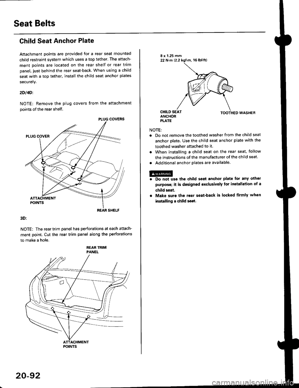
Child Seat Anchor Plate
Attachment points are provided for a rear seat mounted
child restraint system which uses a top tether. The attach-
ment points are located on the rear shelf or rear trim
panel, just behind the rear seat-back. When using a child
seat with a top tether, install the child seat anchor plates
securely.
2Dl4Di
NOTE; Remove the plug covers from the attachment
points of the rear shelf.
3D:
NOTE: The reartrim panel has perforations at each attach-
ment point. Cut the rear trim panel along the perforations
to make a hole.
REAR TRIMPANEL
PLUG COVERS
REAR SHELF
POINTS
20-92
NOTE:
TOOTHED WASHEB
Do not remove the toothed washer from the child seat
anchor plate. Use the child seat anchor plate with the
toothed washer attached to it.
When installing a child seat on the rear seat, follow
the instructions of the manufacturer of the child seat
Additional anchor olates are available.
@r Do not us6 the child seat anchor plate for any othel
purposs; it is designed exclusively tor installation of a
child 3eat.
. Make suro the rear seat-back is locked firmly when
installing 8 child seat.
Page 1371 of 2189
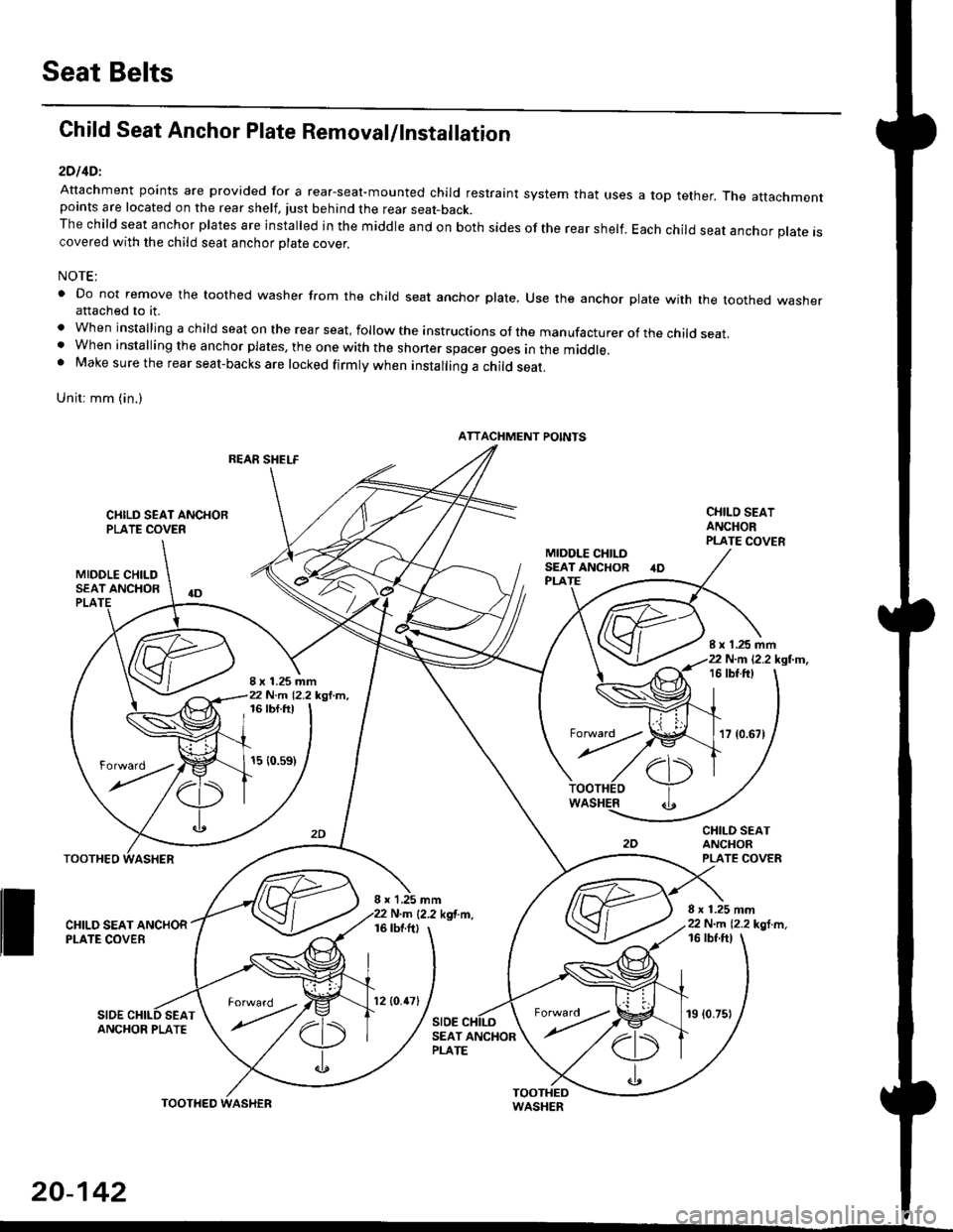
Seat Belts
Child Seat Anchor Plate Removal/lnstallation
2DllDl
Attachment points are provided for a rear-seal-mounted child restraint system that usespoints are located on the rear shelf, tust behind the rear seat-back.The child seat anchor plates are installed in the middle and on both sides of the rear shelf.covered with the child seat anchor olate cover.
a top tether. The attachment
Each child seat anchor plate is
NOTE:
' Do not remove the toothed washer from the child seat anchor plate, Use the anchor plate with the toothed washerattached to it.
. When installing a child seat on the rear seat, follow the instructions of the manufacturer of the child seat.. When installing the anchor plates, the one with the shoner spacer goes in the middle.. Make sure the rear seat-backs are locked firmly when installing a child seat.
Unit: mm (in.)
REAR SHELF
CIIILD SEAT ANCHORPLATE COVER
MIDOLE CHILDSEAT ANCHOR
CHILO SEATANCHORPLATE COVER
CHILD SEATANCHORPLATE COVER
8 x 1.25 mm22 N.m 12.2 kgl m,
PLA
8 x 1.25 mm22 N.m 12.2 kgl.m,
I x 1.25 mm22 N.m 12.2 kgl.m,16 tbt.ftt
17 {0.67)
16 tbf.ft)
15 {0.s9)
WASHER
rl)
.t
TOOTHEO
ll ff*,".rd,',i"'"o*
SIDESEAT
I x 1,25 mmN.m {2.2 kgf.m.16 tbtftl
SIDE
16 tbf ftl
ANCHOR PLATESEAT ANCHORPLATE
ATTACHMENT POINTS
torward .
20-142
TOOTHED
12lO.47l19 (0.75)