Page 1761 of 2189
)r
l-J
SIEMENS SRS Unit
SRS indicator lightDTCPossible cause Corregtive astionSee page
doesn't come on
none(doesn't
come on)
FaulW SRS indicator light circuitTrou bleshooting24-26
comes on
none*3
(doesn't
go ofl)
Faulty SRS indicator light circuit, internal
failure of SRS unit, faulty SRS power supply
{VB line)
Troubleshooting24-34
1-1Open or increased resistance in the driver's
airbag inflator
Troubleshooting
24,42
1-3Short to another wire in the driver's airbag
inflator or decreased resistance24-44
1-4Short to power in the driver's airbag inflator24-46
Shon to ground in the driver's airbag inflator24 48
2-1Open or increased resistance in the passengers
airbag inflator
Troubleshooting
24-50
2-3Short to another wire in the passenger's
airbag inflator or decreased resistance24-52
2-4Short to power in the passenger's airbag
inflator24-54
2-5Short to ground in the passenger's airbag
inflator24-56
,-. ^
l) t (cont,d)
24-23
d
Page 1762 of 2189
Troubleshooting
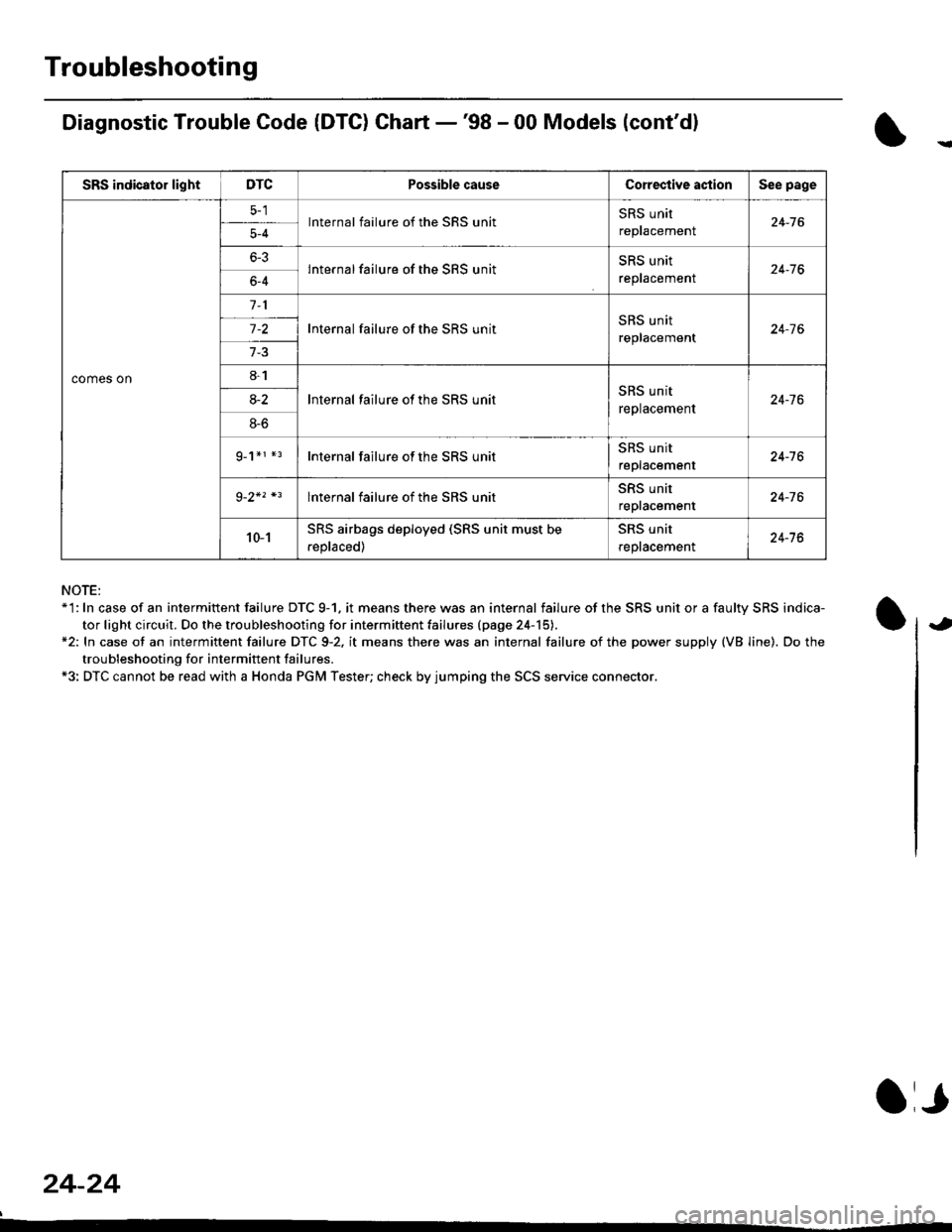
Diagnostic Trouble Code (DTG) Chart -'98 - 00 Models (cont'dl
NOTE:*'l: In case of an intermittent failure DTC 9-1. it means there was an internal failure of the SRS unit or a faulty SRS indica-
tor light circuit. Do the troubleshooting for intermiftent failu.es (page 24-15).*2: In case ot an intermittent failure DTC 9-2. it means there was an internal failure of the power supply (VB line). Do the
troubleshooting for intermift ent failures.*3: DTC cannot be read with a Honda PGM Tester; check by jumping the SCS service connector.
24-24
a,
SRS indicator lightDTCPossible causeCorective actionSee page
comes on
lnternal failure of the SRS unitSRS unit
repracemenl24-765-4
6-3lnternal failure of the SRS unitSRS unit
reptacemenr24-766-4
Internal failure of the SRS unitSRS unit
replacement24-7 6
8-1
lnternal failure ot the SRS unitSRS unit
replacement24-7 68-2
8-6
g_1*r *rInternal failure of the SRS unitSRS unit
replacement24-16
lnternal failure of the SRS unitSRS unit
repracemenl24-76
10-1SRS airbags deployed (SRS unit must be
.eplaced)
SRS unit
reptacemenl24-76
Page 1763 of 2189
SRS Indicator Light Wire Connections
SRS Indicator Light Power Circuit
DASHBOARD WIRE HARNESS
To UNDER-DASHFUSE/RELAY BOX -
20P CONNECTOR
SRS Indicato. Light Control Circuit
To SRS UNIT
tI
SRS MAIN HARNESS
C41 1, C412 : Terminal sido of mdlo t6rminalsC501, C5O2, C508, C801. C802, C807 : Wi.6 sidc of fomalo t.rminals
MAIN WIBE HARNESS
BLU
C508 -+ To GAUGE ASSEMBLY
c41 1
To GAUGE ASSEMBLY
at
C501 : DASHBOARDWIRE HARNESS 2oP CONNECTORC508 : DASHBOARD wlRE HARNESS 5P CONNECTORC801 : SRS MAIN HARNESS 2P CONNECTORC807 : SRS MAIN HARNESS 18P CONNECTOR
C802 : SRS MAIN HARNESS 3P CONNECTORC412 : MAIN WIRE HARNESS 3P CONNECTORC41 1 : MAIN WIRE HARNESS 24P CONNECTORC502 : DASHBOARD WIRE HARNESS 24P CONNECTOR
GRY
OI
24-25
Page 1766 of 2189
Troubleshooting
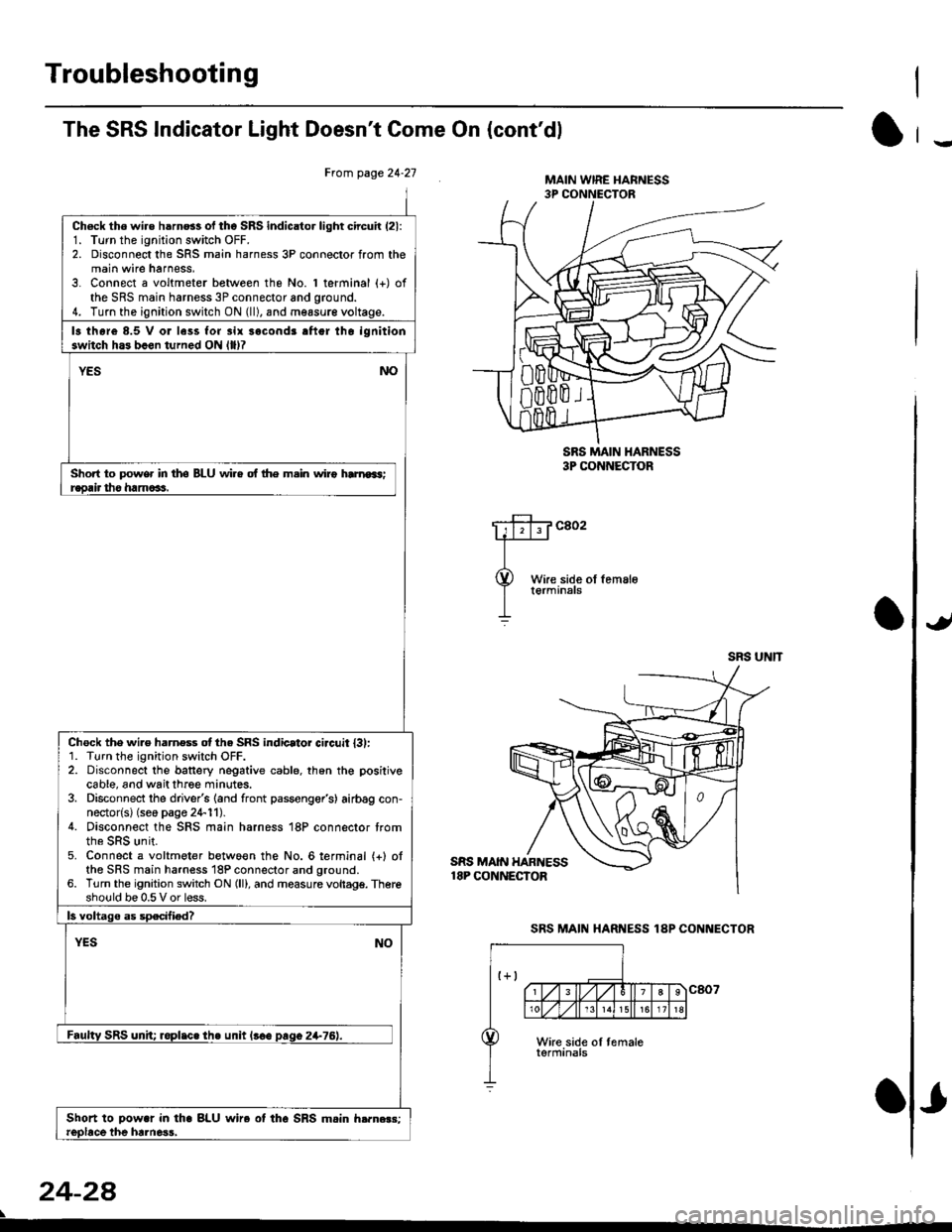
The SRS Indicator Light Doesn't Come On (cont'dl
Frcm page 24.21
Ch6ck tho wire h6rn6s of tho SRS indicator light circuir (21:
1. Turn the ignition switch OFF.2. Disconnect the SRS main harness 3P connector from themain wire harness,3. Connect a voltmeter between the No. 1 terminal (+) ofthe SRS main harness 3P connector and ground.4. Turn the ignition switch ON (ll), and measur€ voltage.
13 thore 8.5 V or less for 3ir sacond3 aftgr tho ignitionswitch h.3 b.en turned ON llllT
YESNO
Short to power in tho BLU wi.e of lhe m.in wiro hrnroas;r€orir tho ham6as.
Chock the wi.e harness otthe SRS indicator ci.cuit l3l:1. Turn the ignition switch OFF.2. Disconnect the banery negative cable. th6n the positivecable, and wait three minutes.3. Disconnect the driver's (and front passenger's) airbag con-nector{s} (seo page 24-11).4. Disconnect the SRS main harness 18P connector trom
5. Connect a voltmeter betwo€n the No. 6lerminal {+} ofthe SRS main harness 18P connector and ground.6. Turn the ignition switch ON (ll), and measure vollagg. Thereshould be 0.5 V or less.
ls voltago as specified?
YESNO
Faultv SRS unh; roplic. the unit l!€e paqo 2+76).
Shoft to Dowar in tha BLU wire ot tho SRS mein h.rn.r3:reobce the hrlne3s,
24-2a
SRS MAIN HARNESS18P CONNECTOR
MAIN WIRE I{ARNESS3P CONNECTOR
SRS MAIN I{ARNESS3P CONNECTOR
c802
SRS UNIT
SRS MAIN HARNESS 1AP CONNECTOR
-
Page 1785 of 2189
)
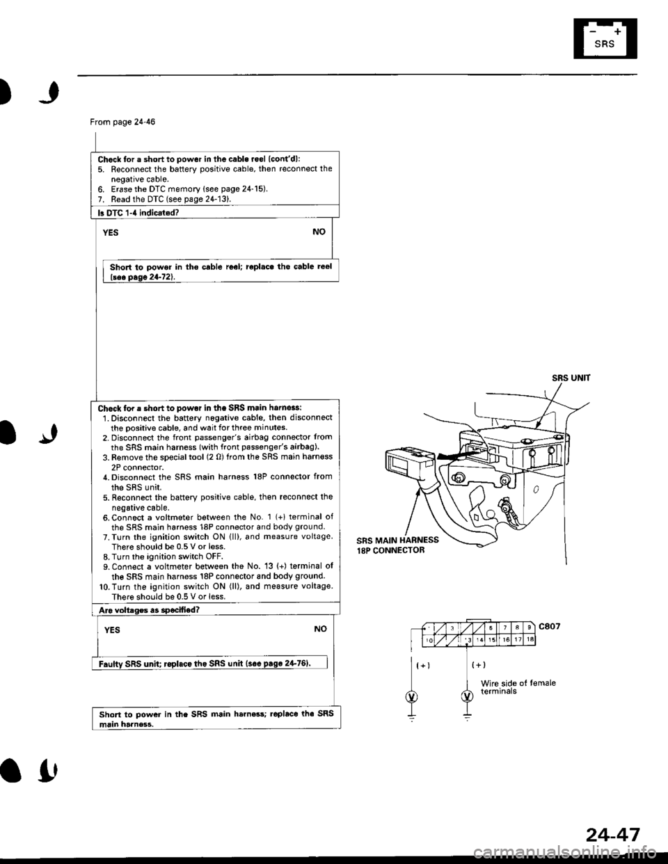
From page 24-46
Chock for a short to power in the cabls roel lcont'dl:5. Reconnect the battery positive cable, then reconnect thenegative cable.6. Erase the DTC memory lsee page 24-15).7. Read the DTC (see pa1e24-131.
b DTC 1-4 indicat€d?
YESNO
Short to power in tho cable reel; roplac. tho cable reel
lsee Dase 24-721.
Chock for e short to powot in the SRS main hornoas:
1. Disconnect the battery nogative cable, then disconnect
the positive cable, and wait for three minutes.2- Disconnect the front passenger's airbag connector lrom
the SRS main harness (with front passenger's airbag).
3. Remove the special tool (2 0) trom the SRS main harn€ss
2P connector./t. Disconnect the SRS main harness 18P connector from
the sRs unit.5. Reconn6ct the battery positive cable, then reconnect the
negative cable.6. Connect a voltmeter between the No. 1 {+i terminal of
the SRS main harness 18P connector and body ground.
7. Turn the ignilion switch ON lll), and measure voltageThere should be 0.5 V or less.8. Turn the ignition switch OFF.9. Connect a voltmeter between the No. 13 (+) torminal ol
the SRS main harness 18P connector 8nd body ground.
lO.Turn the ignition switch ON (ll), and measure voltage
There should be 0.5 V or less.
Aro voltrges a3 specified?
YESNO
Fauftv SRS unh; roplacc tho SRS unh {soe pago 2+761'
Short to power in the SRS main h.rness; .eplace rhe SRS
main harness.
SRS UNIT
IJ
a0
24-47
Page 1792 of 2189
Troubleshooting
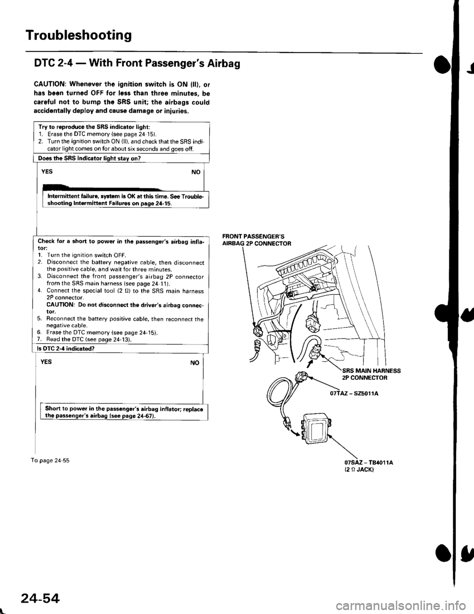
JDTC 2-4 - With Front Passenger's Airbag
CAUTION: Whenever the ignition switch is ON lll), or
has been turnod OFF for less than throa minutes, be
car.Iul not to bump the SRS unit; the airbags could
accidentally deploy and cause damage or iniuries.
Try to r€producethe SRS indicalor light:1. Erase the DTC memory (see page 24 15).2. Turn the ignition switch ON (ll), and check that the SRS indicator light comes on Ior about six seconds and goes off.
Does the SRS indicator light stay on?
YESNO
lDtermittenl failure, syltom b OK at this tima. S€e Trouble.shooting Int€rmittent Failuros on page 24-15.
Check lor a short to pow6r in the passenger's airbag intla-tor:1. Turn the ignition switch OFF.2. Disconnect the battery negative cable, then disconnectthe positive cable, and wait for three minutes.3. Disconnect the front passenger's airbag 2P connectorfrom the SRS main harness lsee page 2/t 11).4. Connect the special tool (2 O) to the SRS main harness2P connector.CAUTION: Do not disconnect the driver's airbag connec-tor.5, Reconnect the battery posit;ve cable, then reconnect thenegative cable.6. Erase the DTC memory (see page 24-15).7. Bead the DTC (see page 24-13).
ls OTC 2-4 indicatod?
YESNO
Short to power in the passenger's airbag inflator; replacetho passenger's airbag lsee page 24-67)
To page 24 55
AZ - SZ5011A
07sAz - TB4011A12 0 JACKI
L
MAIN HARNESS
24-54
Page 1793 of 2189
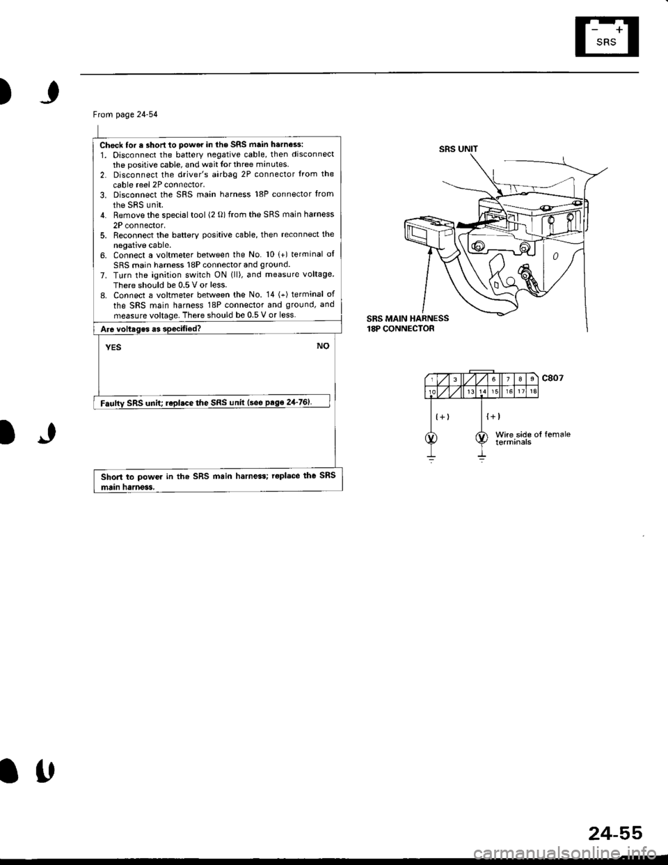
)
Ftom page 24-54
Check lor e short to power in lhe SRS main harness:
1. Disconnect the battery negative cable, then disconnect
the positive cable, and wait Ior three minutes.
2. Disconnect the driver's airbag 2P connector lrom the
cable reel 2P connector.3. Disconnect the SRS main harness 18P connector trom
the sRs unit.4. Remove the special tool (2 o) from the SRS main harness
2P connector,5. Reconnect the baftery positive cable, then reconnect the
negative cable.6. Connect a voltmeter between the No. 10 (+) terminal of
SRS main harness 18P connector and ground.
7. Turn the ignition switch ON lll), and measure voltage
There should be 0.5 V or less.
L Connect a voltmeter between the No. 14 (+) terminal of
the SRS main harness 18P connector and ground, and
measure voltage. There should be 0.5 V or less.
A16 voltages as specified?
YESNO
Fauftv SRS unit; repl.ce the SRS unil (see ptge 24-761
Shon to power in th. SRS main harness; roplace the SRS
main hanes3,
SRS UNIT
1J
Itt
24-55
Page 1798 of 2189
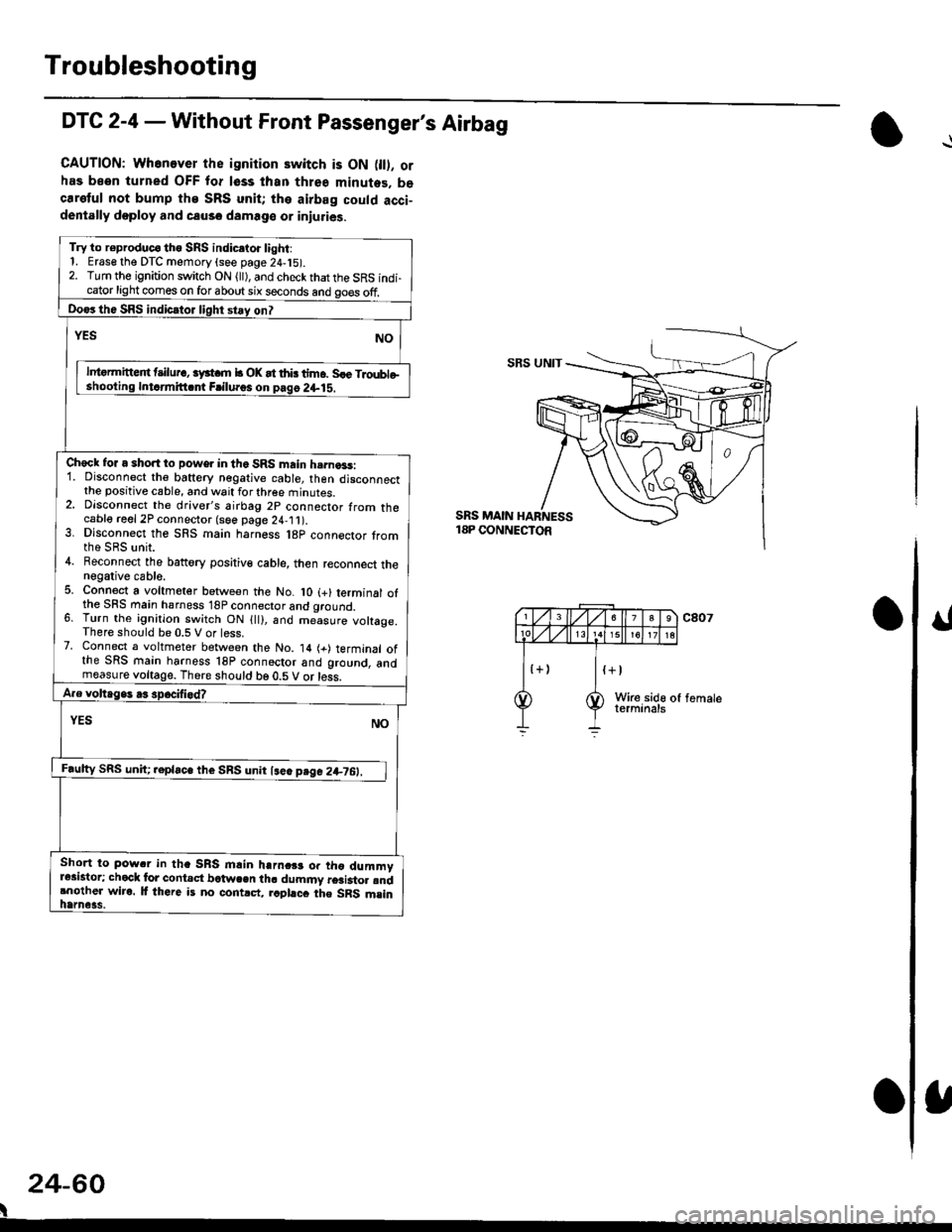
Troubleshooting
DTC 2-4 - Without Front Passenger's Airbag
CAUTION: Whenever the ignition switch is ON 0l). orhas been turned OFF for lsss lhan three minutes. becaretul not bump the SRS unit; the airbag could acci-dentally doploy and causo damage or iniuries.
Try to r€produc€ tho SRS indic.to. light:1. Erase the DTC memory (see page 24,15).2. Turn the ignition switch ON (ll), and check that the SRS indi-cator light comes on for about six seconds and go€s off.
Do€rthe SRS indicrtor light stay on?
NOrEs
lntormitteit t ilur., iyst m b OK at thb tim6. Sle Troubleshooling Intdmitt.nt Frilu.os on pag6 2+lS.
Check for a short to power in the SRS main h.rna3s:1. Disconnect the baftery negative cable, then disconnectthe positive cable, and wait for three minutes.2. Dlsconnect the driver's airbag 2p connector from thecable reel 2P connector (see page 24,11).3. Dlsconnect the SRS main harness l8p connector tromthe SRS unit.4. Beconnect the battory positiv€ cable, then reconnect thenegative cable.5. Connect a voltmeter between the No. lO (+) terminal ofthe SFS main hsrness 18P connector and qround.6. Turn the ignition switch ON {ll), and me-asure voltage.There should be 0.5 V or less.7. Connect a voltmeter between the No. 14 (+) terminal ofthe SRS main harness 18P connoctor and ground, andmeasure voltage. There should be 0.5 V or less.
A.e voltage. .3 spocifi.d?
YES NO
F.ulty SRS uniC .epla"" tl,. SnS unn l""" p"g" 2+7O:_l
Short to pow.r in tha SRS mlin harnc$ or tho dummyr*istor; chock lor contact bctwcen th. dummy r6ai3to. rndrnother wiro. lf there is no contrct, rcphcc the SRS msinhame3s.
SBS UNIT
SRS MAIN18P CONNECTOR
24-60
I