Page 639 of 2189
Change Holder AssemblY
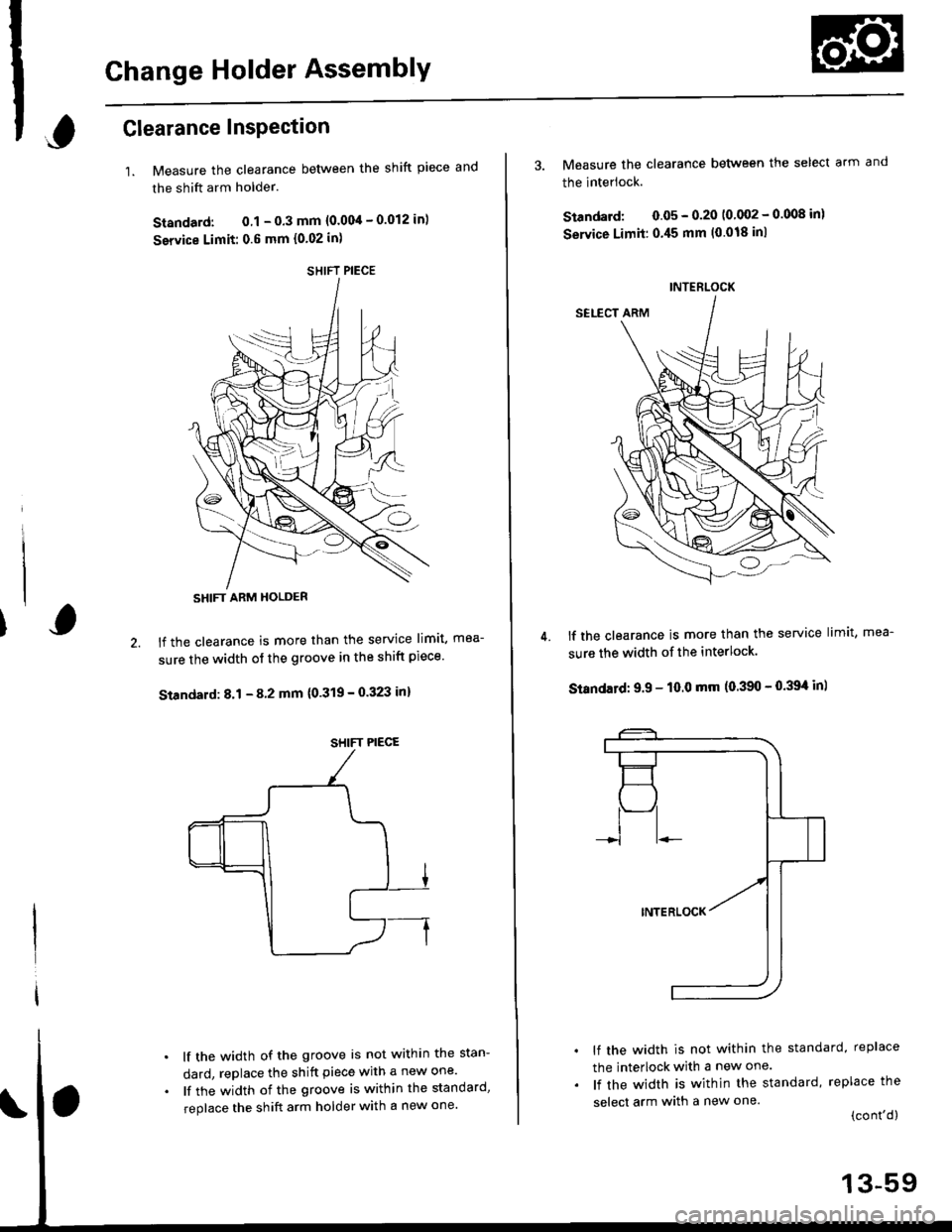
,Glearance InsPection
1.Measure the clearance between the shift piece and
the shift arm holder.
Standard: 0.1 - 0.3 mm {0.004 - 0.012 in)
service Limit: 0.6 mm {0.02 in)
lf the clearance is more than the service limit, mea-
sure the width of the groove in the shift piece'
Standard: 8.1 - 8 2 mm {0'319 - 0.323 in}
lf the width of the groove is not within the stan-
dard, replace the shift piece with a new one'
lf the width of the groove is within the standard,
replace the shift arm holder with a new one'
SHIFT PIECE
SHIFT ARM HOLDER
SHIFT PIECE
4.
3. Measure the clearance between the select arm and
the interlock.
Standard: 0.05 - 0.20 10 002 - 0.008 inl
Service Limit:0.45 mm (0.018 inl
lf the clearance is more than the service limit, mea-
sure the width of the interlock.
Standatd: 9.9 - 10.0 mm (0.390 - 0.39't in)
lf the width is not within the standard, replace
the interlock with a new one.
lf the width is within the standard, replace the
select arm with a new one.(cont'd)
INTERLOCK
13-59
Page 641 of 2189
UO
11. Measure the clearance between the select arm and
the change Piece.
Standard: 0.05 - O'25 mm 10'002 - 0'010 in)
Servica Limii: 0.5 mm {0.02 in)
lf the clearance is more than the service limit, mea-
sure the width of the change Plece.
Standard: 12.05 - 12.15 mm {0.47'|{ - 0 47tI| inl
CHANGE PIECE
lf the width is not within the standard, replace
the change Piece with a new one'
lf the width is within the standard, replace the
select arm with a new one.
't2.
a
a
SELECT ARM
Removal
1. Bemove the shift piece shaft. then remove the shift
piece and the interlock.
SHIFT PIECE SHAFT
INTERLOCK
2. Remove the change holder assembly'
13-61
Page 646 of 2189
Shift Fork Assembly
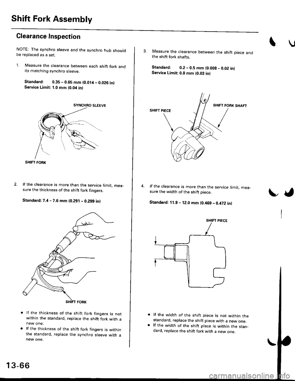
Clearance Inspection
NOTE: The synchro sleeve and the synchro hub shouldbe replaced as a set.
1. Measure the clearance between each shift fork andits matching synchro sleeve.
Standard: 0.35 - 0.65 mm {O.Olit - 0.026 inlService Limit: 1.0 mm t0.04 inl
SHIFT FOBK
lf the clearance is more than the service limit. mea_sure the thickness of the shitt fork finoers.
Standard: 7.4 - 7.6 mm (0.291 - 0.299 in)
lf the thickness of the shift fork frngers rs notwithin the standard, replace the shift fork with anew one.
lf the thickness of the shift fork fingers is withinthe standard, replace the synchro sleeve with a
13-66
3. Measure the clearance between the shift piece andthe shift fork shafts.
Standard: 0.2 - 0.5 mm (0.008 - 0.02 inlService Limit: 0.8 mm {0.03 in)
lf the clearance is more than the service limit. mea-sure the width of the shift Diece.
Standard: 11.9 - 12.0 mm (0.469 - 0.it72 in)
lf the width of the shift piece is not within thestandard, replace the shift piece with a new one.lf the width of the shift piece is within the stan_dard, replace the shift fork with a new one.
t,
SHIFT PIECE
Page 832 of 2189
Gountershaft
Inspection (cont'dl
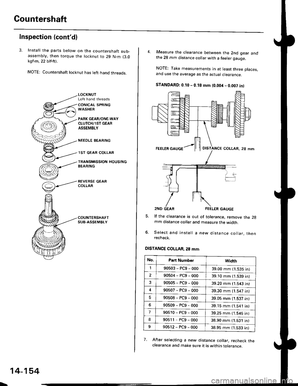
3. Install the parts below on the countershaft sub-assembty, then torque the locknut to 29 N.m (3.0kql.m , 22 blf.ftt .
NOTE: Countershaft locknut has left hand threads.
(=)-----'
v
LOCKNUTLeft hand threads
CONICAL SPRINGWASHER
PARK GEAR/ONE.WAYCLUTCH/1ST GEARASSEMBLY
NEEOLE BEARING
.I ST GEAR COLLAR
TRANSMISSION HOUSINGBEARING
REVERSE GEARCOLLAR
\
14-154
4. Measure the clearance between the 2nd gear andthe 28 mm distance collar with a feeler gauge.
NOTE: Take measurements in at least three places.and use the average as the actuar ctearance.
STANDAFD: 0.10 - 0.18 mm {0.004 - 0.002 inl
lf the clearance is out of tolerance. remove the 2gmm distance collar and measure the width.
Select and install a new distance collar, thenrecheck.
DISTANCE COLLAR, 28 mm
7. Afret selecting a new distance collar, recheck theclearance and make sure it is within tolerance.
OISTANCE COLLAR, 28 mm
No.Part Numb€rwidrh
190503-PCg-00039.00 mm (1.535 in)
290504-PCg-00039.10 mm { 1.539 in)
90505-PCg-00039.20 mm (1.543 in)
90507-PCg-00039.30 mm {1.547 in)
90508-PC9-00039.05 mm (1.537 in)
90509-PCg-00039.15 mm (1.541 in)
790510-PCg-00039.25 mm ( 1.545 in)
I90511-PCg-00038.90 mm (1.531 in)
90512-PCg-00038.95 mm (1.533 in)
Page 1272 of 2189
Quarter Glass
Installation (cont'd)
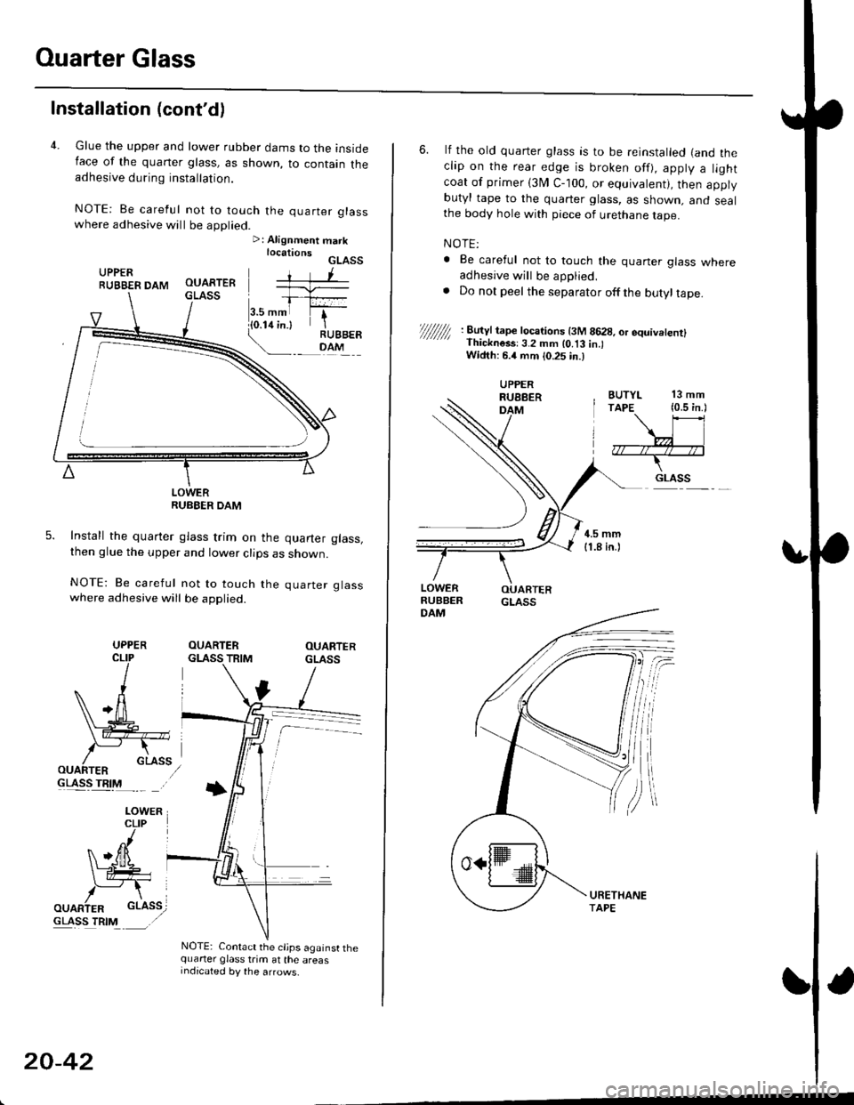
4. Glue the upper and lower rubber dams to the insideIace of the quaner glass, as shown, to contain theadhesive during installation.
NOTE: Be careful not to touch the quarter glasswhere adhesive will be applied.>: Alignment marklocationsGLASSUPPERRUBBER DAM
LOWERRUBEER DAM
Install the quarter glass trim on the quarter glass,then glue the upper and lower clips as shown.
NOTE: Be careful not to touch the quarter glasswhere adhesive will be applied.
OUARTERGLASS TRIMOUARTERGLASS
GLASS TRIM
NOTE: Contact the cljps against thequarter glass trim at the areasIndicated by the arrows.
UPPER
20-42
6. lf the old quarter glass is to be reinstalled (and theclip on the rear edge is broken off), apply a lightcoat of primer (3I/ C-100, or equivalent), then applybutyl tape to the quarter glass, as shown. and sealthe body hole with piece of urethane tape.
NOTE:
. Be careful not to touch the quaner glass whereadhesive will be applied,. Do not peel the separator offthe butyltape.
//////// '. 8�u'Jt tape tocarions t3M 8628, or equivetenrl' Thickness:3.2 mm lo.t3 in.lWidth: 6.4 mm {0.25 in.)
BUTYL 13 mmTAPE (0.5 in.l
\\l
,7r--/r4--;*--T-
.. GLASS
UPPERRUEBERDAM
Page 1276 of 2189
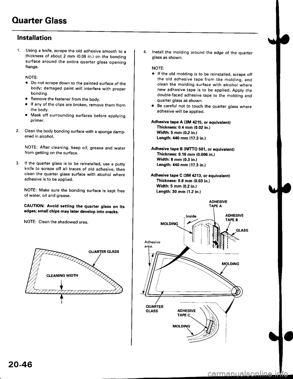
Ouarter Glass
1.
Installation
Using a knife, scrape the old adhesive smooth to athickness of about 2 mm (0.08 in.) on the bondingsurface around the entire quarter glass openingflange.
NOTE:
. Do not scrape down to the painted surface of thebody; damaged paint will interfere with proper
a
a
bonding.
Remove the fastener from the body.lf any of the clips are broken, remove lhem fromthe body.
Mask off surrounding surfaces before applyingpnmer.
Clean the body bonding surface with a sponge dampened in alcohol.
NOTE: After cleaning, keep oil, grease and waterfrom getting on the surface.
lf the quarter glass is to be reinstalled, use a puttyknife to scrape off all traces of old adhesive. thenclean the quarter glass surface with alcohol whereadhesive is to be applied.
NOTE: Make sure the bonding surface is kept freeof water. oil and grease.
CAUTION: Avoid setting the quarter glass on itsodges; small chips may later develop into cracks,
NOTE: Clean the shadowed area.
20-46
4. Install the molding around the edge of the quarterglass as shown.
NOTE:
. lf the old molding is to be reinstalled, scrape offthe old adhesive tape from the molding, andclean the molding surface with alcohol wherenew adhesive tape is to be applied. Apply thedouble-faced adhesive tape to the molding andquarter glass as shown.. Be careful not to touch the quarter glass whereadhesive will be aoDlied.
Adhesiv€ tspe A (3M 4215, or equivalent)Thicknsss: o.il mm (0.02 in.l
Widih: 5 mm {0.2 in.}
Length: /140 mm {17.3 in.)
Adhesive tap6 I (NITTO 501, or equivatontlThickness: 0.16 mm {0.006 in.)
Width: I mm {0.3 in.}
Longlh: 4it0 mm (17.3 in.)
Adhosiv€ tape C (3M /P13. or equivalentl
Thickness: 0.8 mm (0.03 in.l
Width: 5 mm (0.2 in.)
Length: 30 mm (1.2 in.)
ADHESIVE
Page 1640 of 2189
Headlights
Adjustment (cont'dl
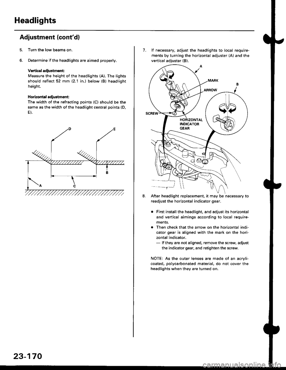
Turn the low beams on.
Determine if the headlights are aimed properly.
Vsrtical adiustmsnt:
Measure the height of the headlights (A). The lights
should reflect 52 mm \2.1 in.) below (B) headlight
height.
Horizontal adi$tment:
The width of the refracting points (C) should be the
same as the width of the headlight central points (D,
23-170
7. lf necessary, adjust the headlights to local require-
ments by turning the horizontal adjuster (A) and the
vertical adjuster (B).
After headlight replacement, it may be necessary to
readjust the horizontal indicator gear.
. First installthe headlight, and adjust its horizontal
and vertical aimings according to local require-
ments.
. Then check that the arrow on the horizontal indi-
cator gear is aligned with the mark on the hori-
zontal indicator,- lf they are not aligned, remove the screw, adjust
the indicator gear, and retighten the screw.
NOTE: As the outer lenses are made of an acryli-
coated, polycarbonated material, do not cover the
headlights when they are turned on.
Page:
< prev 1-8 9-16 17-24