Page 1522 of 2189
Connector ldentification and Wire Harness Routing
Front Passenget's Door Wire Harness {Sedanl
Connector or
Terminal
Number of
CavitiesLocationConnects toNotes
c651
c653
c654
c656
25
2
2
2
8
Passenger's door
Passenger's door
Passenger's door
Passenger's door
Passenger's door
Passenger's door
lnside of right power mirror
Floor wire harness (C557)
Floor wire harness (C557)
Right front door speaker
Front passenge/s power window moror
Front passenger's door lock actuator
Front passenger's power window switch
Right power mirror
*1: With power windows*2: Without power windows
23-52
Page 1535 of 2189

lr-
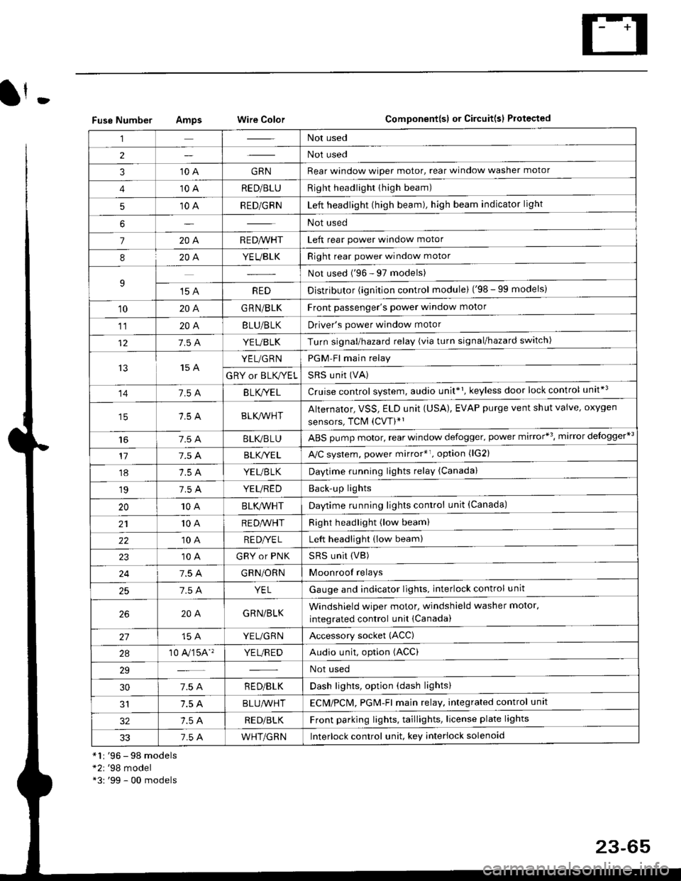
Fuse NumberAmpswire ColorComponent{sl or Circuit(sl Protected
*1r '96 - 98 models*2r '98 model*3: '99 - 00 models
,lNot used
2Not used
310 AGRNRear window wioer motor, rear window washer motor
410 ARED/BLURight headlighr thigh beam)
510 ARED/GRNLeft headlight (high beam), high beam indicator light
6Not used
7204R E D/VVHTLeft rear power window motor
820A.YEUBLKRight rear power window motor
9Not used ('96 - 97 models)
't5 AREDDistributor (ignition control module) ('98 - 99 models)
10204G RN/BLKFront passenger's power window motor
1120ABLU/BLKDriver's power window motor
127.5 AYEUBLKTurn signal/hazard relay (via turn signal/hazard switch)
t515 AYEL/GRNPGM-Fl main relay
GRY or BLK,^/ELSRS u nit (VA)
141.54B LK/YE LCruise control system, audio unit*1, keyless door lock control unit*3
BLK/lr'r'HTAlternator, VSS, ELD unit (USA), EVAP purge vent shut valve, oxygen
sensors, TCM (CVT)*'
t6BLI(,/BLUABS pump motor, rear window defogger. power mirror*3, mirror delogger*3
177.5 ABLK,/YE LA,/C system, power mirror*r. option (lG2)
18YEUBTKDaytime running lights relay (Canada)
197.5 AYEUREDBack'up lights
2010ABLK/VVHTDaytime running lights control unit (Canada)
2110 AREDA/VHTRight headlight (low beam)
2210 ARE DI/E LLeft headlight (low beam)
10 AGRY or PNKSRS UNit (VB)
247.5 AGRN/ORNMoonroof relays
257.5 AYELGauge and indicator lights. interlock control unit
204GRN/BLKWindshield wiper motor, windshield washer motor,
integrated control unit {Canada)
15 AYEL/GRNAccessory socket (ACC)
2a10 A,/'�]5A''YE L/R EDAudio unit, option (ACC)
29Not used
307.5 AR ED/BLKDash lights, option (dash lights)
1.5 ABLUA/VHTECM/PCl\4, PGM-Fl majn relay, integrated control unit
RED/BLKFront parking lights, taillights, license plate lights
337.5 AWHT/GRNlnterlock control unit. key interlock solenoid
23-65
Page 1663 of 2189
Speaker Replacement
Front speaker:
1. Remove the speaker cover.
2. Remove the three screws from the speaker.
3. Disconnect the 2P connector, and remove the door
speaker.
Tweeter:
1. Remove the door panel (see section 20).
2. Disconnect the 2P connector from the tweeter.
3. Remove the mirror garnish.
4, Remove the two screws, then remove the wveeter.
FRONT SPEAKER
TWEETER(}-
23-193
Rear speaker:
1. Remove the rear side shelf or rear shelf (see section
20t.
2. Disconnect the 2P connector from the speaker.
3. Remove the four screws, then remove the speaker.
Hatchback:
Coupe/Sedan:
2P CONNECTOF
2P CONNECTOR
REAR
Page 1676 of 2189
Power Mirrors
Component Location Index
Powel Mirror
Function Test, page 23-2Oj
Power Mirror Test, page 23-210
Replacement, section 20
Actuator Replacement, page 23-2'10
POWEB MIEROR SwlTCHTest, page 23-209
23-206
Page 1678 of 2189
Power Mirrors
UNDER.OASHFUSE/FELAY BOX
Circuit Diagram {With Defogger)
BLK
G551
8LK
I
G551
YEURED
BLUMHT
8LK
II
-f,:
G551
23-208
UNDER-HOOD FUSE/RELAY BOX
/lr,---------- ---zlr
I'BLUELKl'YEUBEO
6
ORN/WHT
Page 1679 of 2189

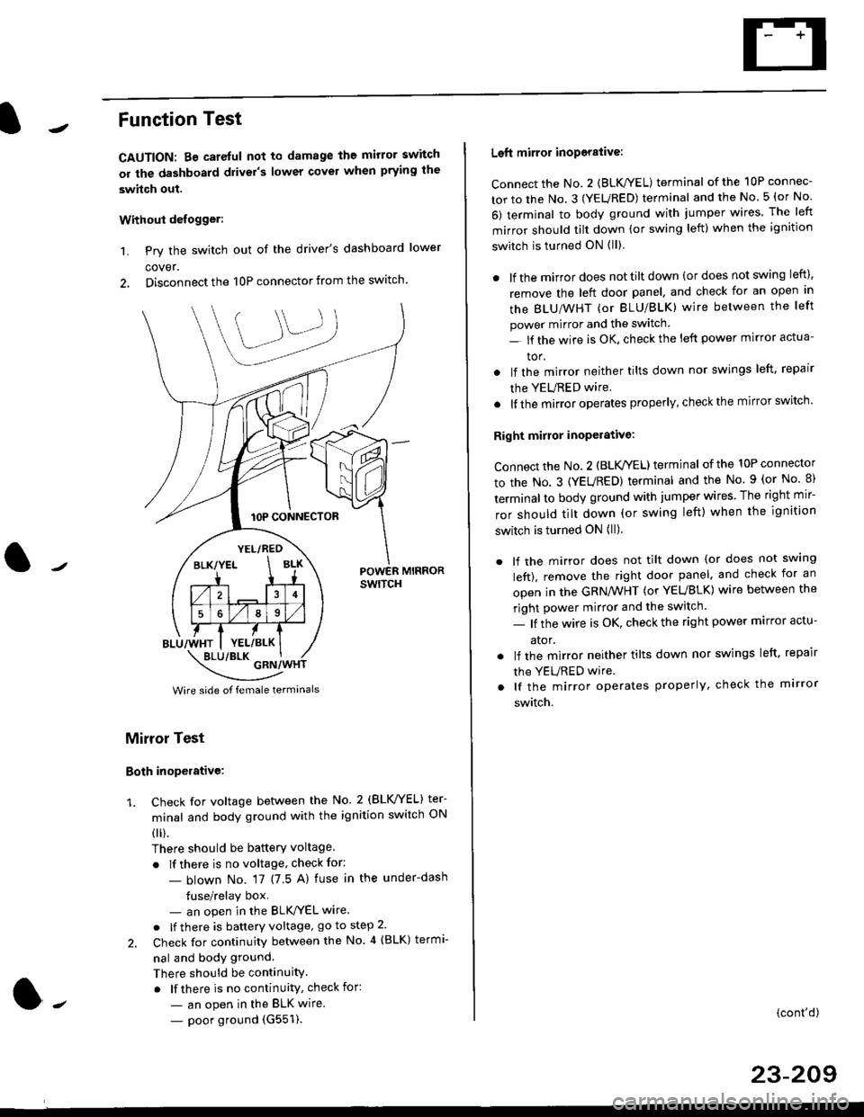
Function Test
CAUTION: Be careful not to damage the mirror switch
or the dashboard drivel's lower covel when prying the
swhch out.
Withoui defogger:
1. Pry the switch out of the driver's dashboard lower
cover.
2. Disconnect the 10P connector from the switch.
lOP CONNECTOR
BLU/WHT
YEL/RED
BLK/YELBLK
4
568
YEL/BLK
POWER MIRRORswtTcH
\:/"*jgil*-(
Wire side of female termanals
Mirror Test
Both inoperative:
1. check for voltage between the No. 2 (BLVYEL) ter
minal and body ground with the ignition switch ON
0 r).
There should be batterY voltage
. If there is no voltage, check for:
- blown No. 17 (7 5 A) fuse in the under-dash
tuse/relay box- an open in the BLK'/YEL wire.
o lf there is battery voltage, go to step 2.
2. Check for continuity between the No 4 (BLK) termi-
nal and body ground.
There should be continuity.
. lf there is no continuity, check for:
- an open in the BLK wire.
- poor ground (G551).
Left mirror inoporalive:
connect the No. 2 {BLK/YEL) terminal of the 10P connec-
tor to the No. 3 (YEURED) terminal and the No 5 (or No
6) terminal to body ground with jumper wires The left
mirror should tilt down (or swing left) when the ignition
switch is turned ON (ll)
. lf the mirror does not tilt down (or does not swing left),
remove the left door panel. and check for an open in
the BLU/WHT (or BLU/BLK) wire between the left
power mirror and the switch
- lf the wire is OK. check the left power mirror actua-
tor.
lf the mirror neither tilts down nor swings left. repair
the YEURED wire.
lf the mirror operates properly, check the mirror switch'
Right mirror inoperative:
Connect the No. 2 (BLK /EL) terminal of the 10P connector
to the No. 3 (YEURED) terminal and the No. 9 (or No 8)
terminal to body ground with jumper wires The right mir-
ror should tilt down (or swing left) when the ignition
switch is turned ON (ll).
. lf the mirror does not tilt down (or does not swlng
left), remove the right door panel. and check for an
open in the GRN/WHT (or YEUBLK) wire between the
right power mirror and the switch.
- lf the wire is OK, check the right power marror actu-
ator.
. lf the mirror neither tilts down nor swings left. repair
the YEURED wire
. lf the mirror operates properly, check the mirror
switch.
(cont'd)
23-209
Page 1680 of 2189

Power Mirrors
Funstion Test (cont'dl
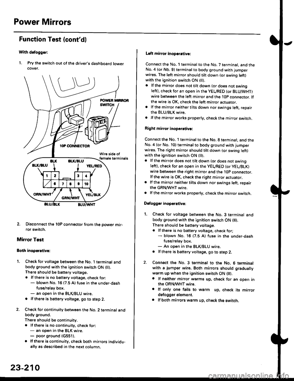
With dcfoggcr:
1. Pry the switch out ot the driver's dashboard lowercover.
2. Disconnect the 10P coonector from the oower mir-ror switch.
Mirror Test
Bolh inoparrtiv.:
1. Check for voltage between the No. 1 terminal andbody ground with the ignition switch ON flt).There should be battery voltage.. lf there is no battery voltage, check to.:- blown No. 16 (7.5 A) fuse in the under-dash
tuse/relay box.- an open in the BLVBLU wrre.
! lf thero is banery voltage, go to step 2.
2. Check for continuity b€tween the No. 2 terminal andbody ground.
There should be continuitv.. ll there is no continuity, check tor:- an open in the BLK wire.- poor ground (G5511.
. lJthere is continuity. check both mirrors individu-ally 8s described in the next column,
23-210
Laft mirror inopcrativ!:
Connect the No. 1 terminal to the No. 7 terminal. and theNo. 4 (or Nb.9) terminalto body ground with jumper
wires. The left mirror should tilt down (or swing left)with the ignition switch ON (ll).
. lf the mirror does not tilt down (o. does not swinglett), check for an open in the YEURED (or BLUMHT)wire between the left mirror and the 10p connector. lfthe wire is OK, check the left mirror actuator.a lf the mirror neither tilts down nor swings left, repairthe BLU/BLK wire.
t lf the mirror works properly, check the mirror switch.
Right mi.ror inopcrativc:
Connect the No. 1 terminal to the No. 8 terminal, and theNo.4 (or No. 10) terminalto body ground with l'umperwi.es. The right mirror should tilt down (or swing lett)with the ignition switch ON (ll).
. lf the mirror does not tilt down {or does not swingleft), check for an open in the YEURED {or YEUBLK)
wire between the right mirror and the l0P connector.lf the wire is OK, check the right mirror actuator,. lf the mirror neither tilts down nor swings left, repairthe GRN/WHT wire.o lf the mirror works properly. check the mirro. switch,
Dafoggcr inoperEtivo:
1. Check for voltage between the No. 3 terminal andbody ground with the ignition switch ON (||).
There should be battery voltage.a lf there is no battery voltage, check for;- blown No. 16 (7.5 A) luse in the under-dash
fuse/rel8y box,- An open in the BLK,iBLU wire.. It there is battery voltage, go to step 2.
2. Connsct the No. 3 tsrminal to the No. 6 terminalwith a iumpsr wire. Both mirrors should gradually
warm up when the ignition switch ON flt).a lf neither mirror warms up, check for an open inthe ORN/WHT wire.. It only on€ lails to warm up, check its mirrordsfogger elem6nt.. lf both mirrors warm up, check ths switch.
Page 1681 of 2189
I
r Switch Test
Without detogg€r:
1. Remove the switch as dsscribed in Function Test
(see page 23-207).
2. Check for continuity betw€en the terminals in each
switch position according to the table.
Mirror Switch:
POWER MIRROB
swlTcH
Terminal
rL*"--_\
23456n9
L
UP-o
o-
DOWNo--oo--o
LEFTo-o--o
RIGHTo--o
o--o
UPo--o
o--o
DOWNo--oo--o
LEFIo--oo--o
RIGHT-o
o--o
l-
23-211
1. Prv the switch out of the dashboard driver's lower
With defogger:
POWER MIRRORswtTcH
Disconnect the 1OP connector from the switch'
Check for continuity between the terminals in each
switch position according to the table
Mirror Switch:
Terminal
Position \l2789't0
L
UPo-o-
-o-o
DOWNo-o--o-a
o-
o-
-o--o
RIGHTo--o
o--O
UPGo-
-o-o
DOWNo--o
G--o
LEFTo--o-oo-
RIGHT
-o
o--o
Dofogger Swhch:
Terminal
Posilion \
2
ONo-/l>\-osv
OFFo---o