Page 855 of 2189

1.Install the ATF magnet and suction pipe collar in the
torque converter housing. if necessary.
lnstall the main seDarator plate and the two dowel
pins on the torque converter housang.
Install the ATF pump drive gear, ATF pump driven
gear and ATF pump driven gear shaft on the torque
converter housing.
NOTE; Install the ATF pump driven gear with its
grooved and chamfered side tacing down.
ATF PUMP
ATF PUMP DRIVENGEAR SHAFT
ATF PUMPDRIVEN GEAR
Grooved and chamferedside taces separalorplate.MAIN SEPARATORPLATE
4.Loosely install the main valve body with five bolts.
Make sure the ATF pump drive gear rotates smoothly
in the normal operating direction and the ATF pump
driven gear shaft moves smoothly in the axial and
normal operating directions.
Install the secondary valve body, separator plate
and two dowel pins on the main valve body.
NOTE: Do not installthe bolts.
6. Install the control shaft in the housing with the con-
trol shaft and manual valve together.
7. lnstall the detent arm and arm shaft in the main
valve body, then hook the detent arm spring to the
detent arm,
SERVO SEPARATOR PLATE
DETENT
MANUAL VALVE
DETENT ARM SPRING
15.
14-177
a
10.
11.
Install the servo body and separator plate on the
secondary valve body ('95 - 98 models: seven bolts.'99 - 00 models: eight boltsl.
For '96 - 98 models: Install the servo detent base
and the ATF strainer (two boltsl.
For'99 - 00 models: Install the ATF strainer (one
bolt).
Tighten the five bolts on the main valve body to 12
N.m ('1.2 kgf.m,8.7 lbf.ft).
Make sure the ATF pump drive gear and ATF pump
driven gear shaft move smoothlY'
lf the ATF pump drive gsar and ATF pump driven
gear shaft do not move freely, loosen ths five bolts
on the main valve body, and disassemble the valve
bodies.
Realign the ATF pump driven gear shaft and reassem-
ble the valve bodies, then retighten the bolts to the
specified torque,
CAUTION: Fsilule to align tho ATF pump driven
goar shaft corr.ctly will rscuh in a s€ized ATF pump
drive goar or ATF pump d ven gear shaft.
Install the stator shaft and stop shaft.
Install the bolts and the shaft stop on the secondary
valve body, then tighten the bolts (three boltsl.
Install the torque converter check valve, cooler relief
valve and valve springs in the regulator valve body.
then install the regulator valve body on the main
valve bodv (one bolt).
Install the lock-up valve body on the regulator valve
bodv (seven bolts).
Install the ATF feed pipes in the main valve bodY,
the three ATF feed pipes in the secondary valve and
the four ATF feed pipes in the servo body. (cont'dl
12.
't 3.
14.
PUMP
Page 996 of 2189

l.
1.
2.
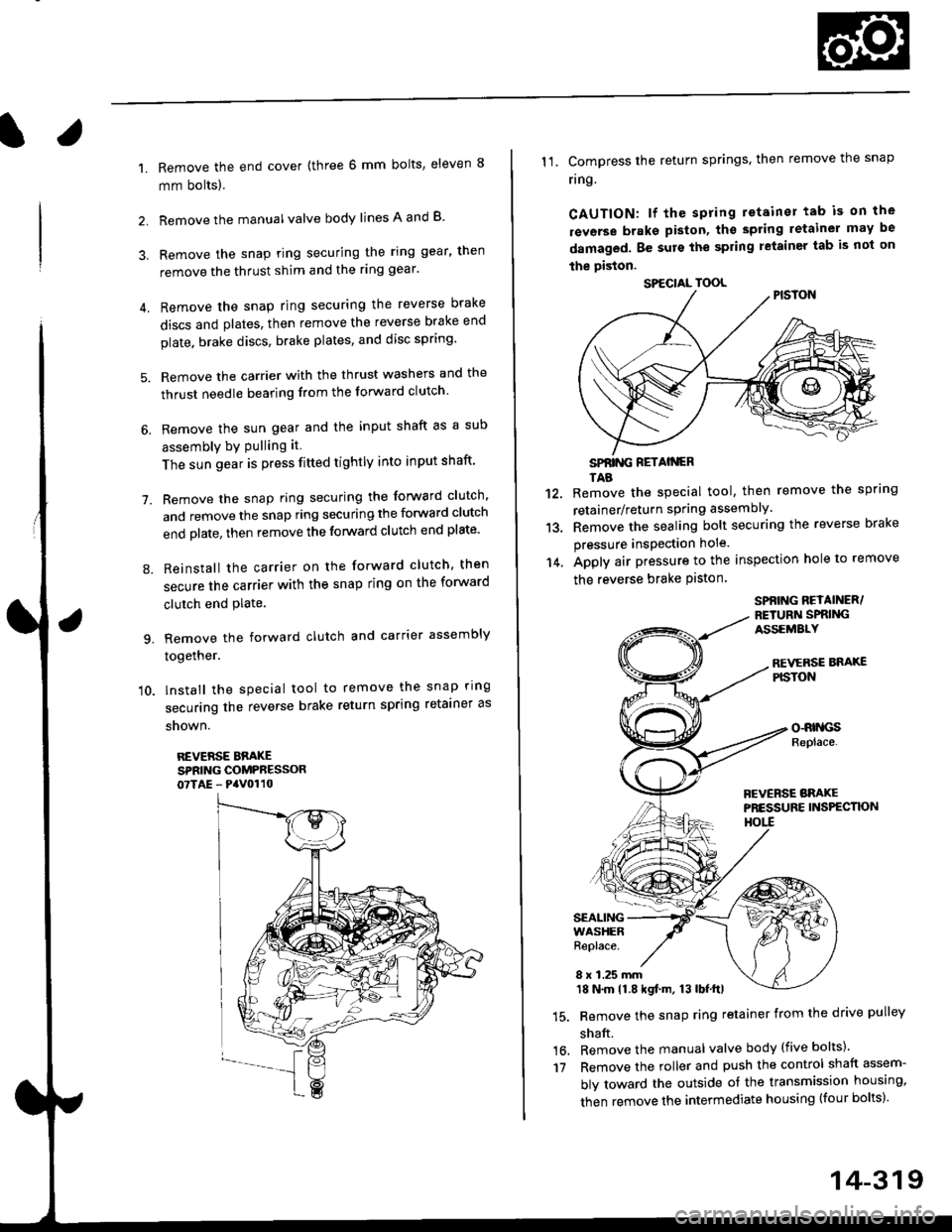
Remove the end cover {three 6 mm bolts, eleven 8
mm bolts).
Remove the manualvalve body lines A and B
3. Remove the snap ring securing the ring gear, then
remove the thrust shim and the ring gear'
4. Remove the snap ring securing the reverse brake
discs and plates, then remove the reverse brake end
plate. brake discs, brake plates, and disc spring'
5. Remove the carrier with the thrust washers and the
thrust needle bearing from the forward clutch
6. Remove the sun gear and the input shaft as a sub
assembly bY Pulling it
The sun gear is press fitted tightly into input shaft'
7. Remove the snap ring securing the forward clutch,
and remove the snap ring securing the forward clutch
end plate, then remove the forward clutch end plate'
8. Reinstall the carrier on the forward clutch, then
secure the carrier with the snap ring on the forward
clutch end Plate.
9. Remove the forward clutch and carrier assembly
together.
'10. lnstall the special tool to remove the snap ring
securing the reverse brake return spring retainer as
snown.
REVERSE BBAKESPRING COMPRESSOR07TAE - PaV0110
11. Compress the return springs. then remove the snap
ring
CAUTION: lf the spring retainer tab is on the
rsverse braks piston, tho spting letainer may be
damaged. Be surs the spring letainer tab is not on
the piston.
SPfiING FETAIiGRTAB
Remove the special tool, then remove the spring
retainer/return spring assembly.
Remove the sealing bolt securing the reverse brake
pressure insPection hole.
Apply air pressure to the inspection hole to remove
the reverse brake Piston
12.
13.
14.
16.'t7
SPBING REYAINER/RETURiI SPRIiIGASSEMALY
REVERSE BNAXEPISTON
o-RrllcsReplace.
FCVERSE BRAKEPRESSURE INS?ECTK)NHOtl
SEALINGWASHERReplace.
8 x 1.25 mm18 N.m 11.8 kgf.m, 13 lbf.ttl
Remove the snap ring retainer from the drive pulley
shaft.
Remove the manual valve body (five bolts)'
Remove the roller and push the control shaft assem-
bly toward the outside of the transmission housing,
then remove the intermediate housing (four bolts)'
SPECIAL TOOL
14-319
Page 1015 of 2189

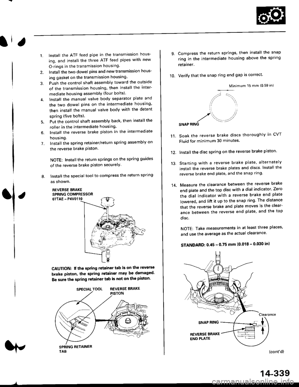
1.
7.
lnstall the ATF feed pipe in the transmission hous-
ing, and install the three ATF feed pipes with new
O-rings in the transmission housing,
Install the two dowel pins and new transmission hous-
ing gasket on the transmission housing.
Push the control shaft assembly toward the outside
of the transmission housing, then install the inter-
mediate housing assembly (four bolts).
lnstall the manual valve body separator plate and
the two dowel pins on the intermediate housing,
then install the rnanual valve body with the detent
spring (five bolts).
Put the control shaft assembly back, then install the
roller in the intermediate housing.
lnstall the reverse brake piston in the intermediate
housing.
Install the spring retainer/return spring assembly on
the reverse brake Piston.
NOTE: Installthe return springs on the spring guides
of the reverse brake piston securely
tnstall the special tool to compress the return spring
as shown.
REVERSE BRAKESPRING COMPRESSOR07TAE - P4V0110
6.
L
1
CAUTION: lf the spring retainer tab is on the reverse
brakc piston, the spring rstainer may be damaged'
Be sure the spring retainer tab is not on the piston'
rp
SPECIALTOOL REVERSEBRAKE
-^
14-339
10.
9.
14.
Compress the return springs, then install the snap
ring in the intermediate housing above the spring
retainer.
Verify that the snap ring end gap is correct'
Mini
/,,- '-t,,,,.
// \i/ ',r
'1 ,
.r' //'/. .-J?RINGSNAP
mum 15 mm 10.59 in)
Soak the reverse brake discs thoroughly in CVT
Fluid for minimum 30 minutes.
Installthe disc spring on the reverse brake piston'
Starting with a reverse brake plate, alternately
install the reverse brake plates and discs lnstall the
reverse brake end plate, and the snap ring'
Measure the clearance between the reverse brake
end plate and the top disc with a dial indicator' Zero
the dial indicator with a reverse brake end plate
lowered, and lift it up to the snap ring The distance
that the reverse brake and plate moves is the clear-
ance between the reverse end plate, and the top
disc.
NOTE: Take measurements in at least three places'
and use the average as the actual clearance'
STANDARD: 0.45 - 0.75 mm (0.018 - 0'030 in)
{cont'd)
11.
12.
13.
Page:
< prev 1-8 9-16 17-24