Page 1533 of 2189
(l'-
Fuse NumberAmpswire ColorComponent(s) or Circuitlsl Protect€d
4180APower distribution
4240AWHT/BLKTo ignition switch (BAT)
437.5 AWHT/REDCeiling light, data link connector, trunk light
4415 AWHT/BLKPGM-Fl main relay
Not used
4640AWHT/BLUPower window motors (via power window relay)
477.5 AWHT/BLUAudio unit, clock, TCM (CVT), ECM/PCM (VBU)
4830AWHTNo.33 (7.5 A) fuse, To combination light switch (headlight)
49Not used
5030AWHT/GRNRear window defogger (via rear window defogger relay)
cl20AWHT/GRNPower door lock control unit, moonroof motor
15 AWHT/GRNHorn system, brake lights, brake signal
10 AWHT/BLKHazard warning light, turn signal/hazard rclay
54404WHT/REDOption {+B)
5540ABLU,A/VHTBlower motor (via blower motor relay)
204WHTCondenser fan motor (via condenser fan relay)
REDl'lc compressor clutch (via IVC compressor clutch relay)
204BLVBEDRadiator fan motor (via radiator fan relay)
23-6
Page 1542 of 2189
Power Distribution
Circuit ldentification (conf dl
IM/T)
rGNrTtoN swrTcH (sT)(From pag€ 23{9)
YBLK ,VHT
t-
I
r**"'.fffr,u,r.*@**-_
lil.BLT(-^,I'/HT -|:1jl- BLT(RED
T
BLK ^/HT - $aner sol€ndd G401
STAFTERCUT RELAYCLUTCH SWITCH
BLIVREO
L-
rGNrTroN swtTcH (sT){From paoe 23{9)
f'7
IIBLK/WHT
NEUTFAL POSITIONswtTcH/ln lL/Tgeat \\posnion swldr/
BLT(RED
-BLK4rrHr
- srarrer sotsnoid
(Fus€felay lox sockol)lrflagGt€d conlrol unit
ELU VHT - PGM-F| main retay
BLUMHT _ ECI\T/PCM
lH#|1'#i,'f,5>-**l e ock connol unit(via intedocf switdr)
Key ints ocl solenoid
23-72
wHr + &3T:$111.9|'ij""'n'"
Page 1557 of 2189
Normally-opsn tYPe:
1. Check for continuity between the terminals
. There should be continuity between the No. 1 and
No. 2 terminals when power and ground are con-
nected to the No. 3 and No 4terminals.
o There should be no continuity between the No 1
and No.2 terminals when power is disconnected'
Terminal
Power iNo.3 - No,4) \
I2
Disconnected
Connectedoo
a
a
a
Power window relaY
Radiator fan relaY
Condenser fan relaY
A/C compressor clutch relaY
Starter cut relay: '98 - 00 models
Horn relay: '98 - 00 models
Five-ierminal type:
1. Check for continuitv between the terminals.
. There should be continuity betlveen the No. 1 and
No. 2 terminals when power and ground are con-
nected to the No. 3 and No 5terminals.
. There should be continuity between the No 2 and
No. 4 terminals when power is disconnected'
--1
I
II
t
Moonroof open relay: '96 - 97 models
Moonroof close relay: '96 - 97 models
(cont'd)
23-87
Terminal
Power (No. 3 - No. 5)\
4
Disconnectedo--o
Connectedo--o
Page 1563 of 2189
Starting System
Component Location Index
A/T GEAR POSITION SW|TCHTest, page 23'154Replacement, page 23-155
STARTER CUT RELAY (M/T}
Test, page 23-86, 87
oo
ool
CLUTCH INTERLOCK
swlTcH
BATTERYTest, page 23-91
STARTERTest, page 23'95Solenoid Test, Page 23 96
Replacement, Page 23-100
Performance Test, Page 23-101
23-93
Page 1565 of 2189

-Starter Test
NOTE; The air temoerature must be between 59 and
100'F (15 and 38"C) before testing.
Recommended Procedure:
. Use a staner system tester.
. Connect and operate the equipment in accordance
with the manufacturer's instructions.
. Test and troubleshoot as described,
Alternate Procedurg:
. Use the following equipment:- Ammeter, 0 - 400 A
- Voltmeter, 0 - 20 V (accurate within 0.1 volt)
- Tachometer, 0 - 1,200 rpm
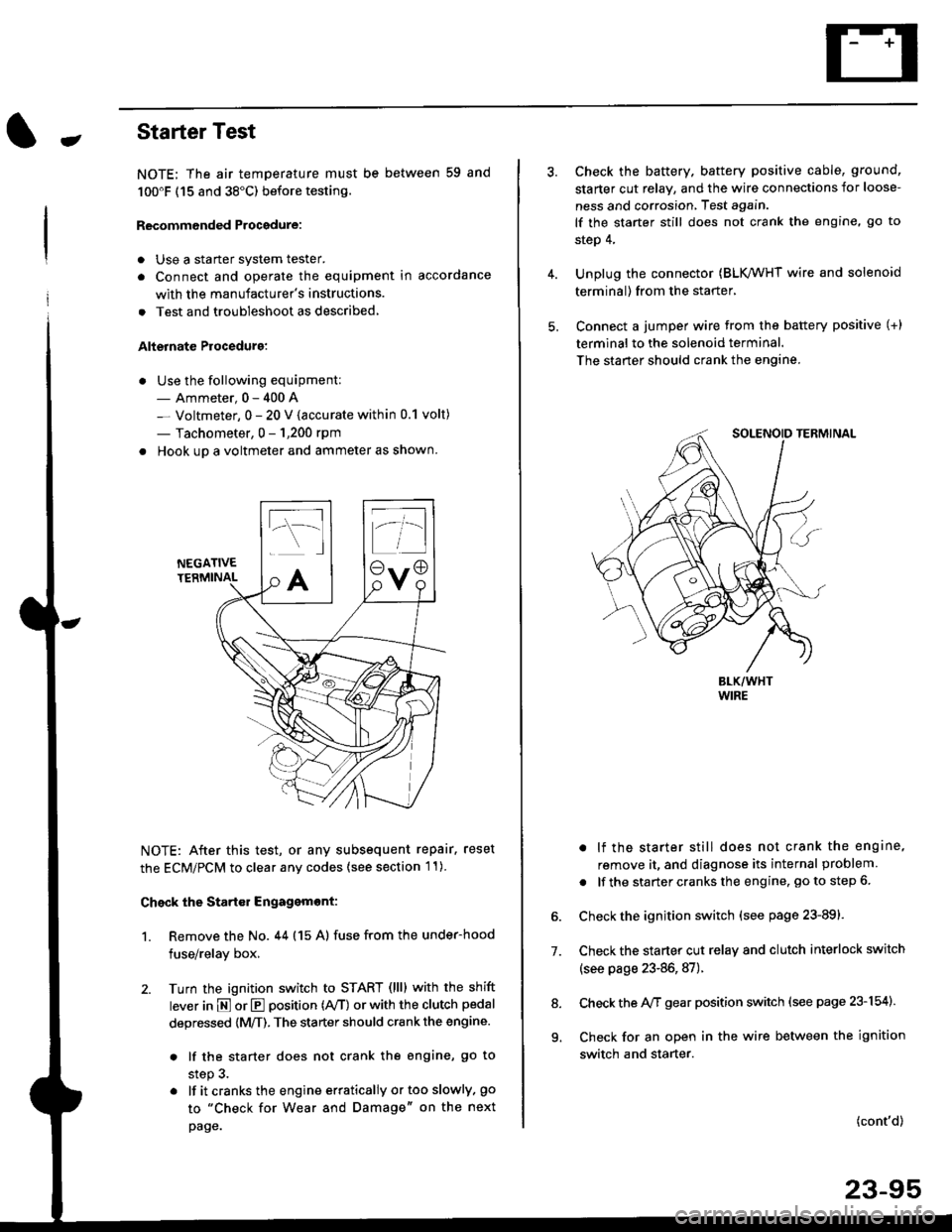
. Hook up a voltmeter and ammeter as shown.
NEGATIVETERMINAL
NOTE: After this test, or any subsequent repair. reset
the ECM/PCM to clear any codes (see section l1)
Check the Start€r Engagemont:
1. Remove the No. 44 (15 A) fuse from the under-hood
fuse/relay box,
2. Turn the ignition switch to START (llll with the shift
lever in E or E position (rVT) or with the clutch pedal
depressed {M/T). The starter should crank the engine.
. lf the starter does not crank the engine, go to
step 3.
. lf itcranksthe engineerraticallyortooslowly, go
to "Check for Wear and Damage" on the next
page.
Check the battery. battery positive cable, ground,
starter cut relay, and the wire connections for loose-
ness and corrosion, Test again.
lf the starter still does not crank the engine, go to
step 4,
Unplug the connector (BLK,/WHT wire and solenoid
terminal) from the starter,
Connect a jumper wire from the battery positive (+)
terminal to the solenoid terminal.
The starter should crank the engine.
. lf the starter still does not crank the engine,
remove it, and diagnose its internal problem
. lf the startercranksthe engine, goto step 6.
Check the ignition switch (see page 23-891.
Check the starter cut relay and clutch interlock switch
(see page 23-86,87).
Check the A/f gear position switch (see page 23-154).
Check for an open in the wire between the ignition
switch and starter.
7.
(cont'd)
23-95
9.
Page 1566 of 2189

Starting System
Starter Test lcont'dl
Ch€ck tor Wear and Damage
The starter should crank the engine smoothly and
steadily, lf the starter engages. but cranks the engine
erratically, remove it, and inspect the starter drive gear
and torque converter or flywheel ring gear for damage.
. Check the drive gear overrunning clutch for binding
or slipping when the armature is rotated with the
drive gear held,- lf damaged. replace the gears.
Check Cranking Voltsge and Curr€nt Draw
Cranking voltage should be no less than 8.5 volts.
Current draw should be no more than 350 amperes.
lf cranking voltage is too low, or current draw too high,
check for;
. dead or low batterv.
. open circuit in starter armature commutator seg-
ments,
. starter armature dragging.
. shorted armature winding.
o excessive drag in engine.
Check Cranking rpm
Engine speed during cranking should be above 100 rpm,
lf speed is too low, check for:
. loose battery or stanerterminals.
. excessively worn starter brushes,
. open circuit in commutator segments.
o dirty or damaged helical spline or drive gear.
. defective drive gear overrunning clutch.
Check Siarter Disengag€ment
With the shift lever in El or @ position (A/T) or with the
clutch pedal depressed (M/T), turn the ignition switch to
START (lll), and release to ON (ll).
The starter drive gear should disengage from the torque
converter or flywheel ring gear when you release the
Key.
lf the drive gear hangs up on the torque converter or fly-
wheel ring gear, check for:
. solenoid plunger and switch malfunction,
. dirty drive gear assembly or damaged overrunning
clutch.
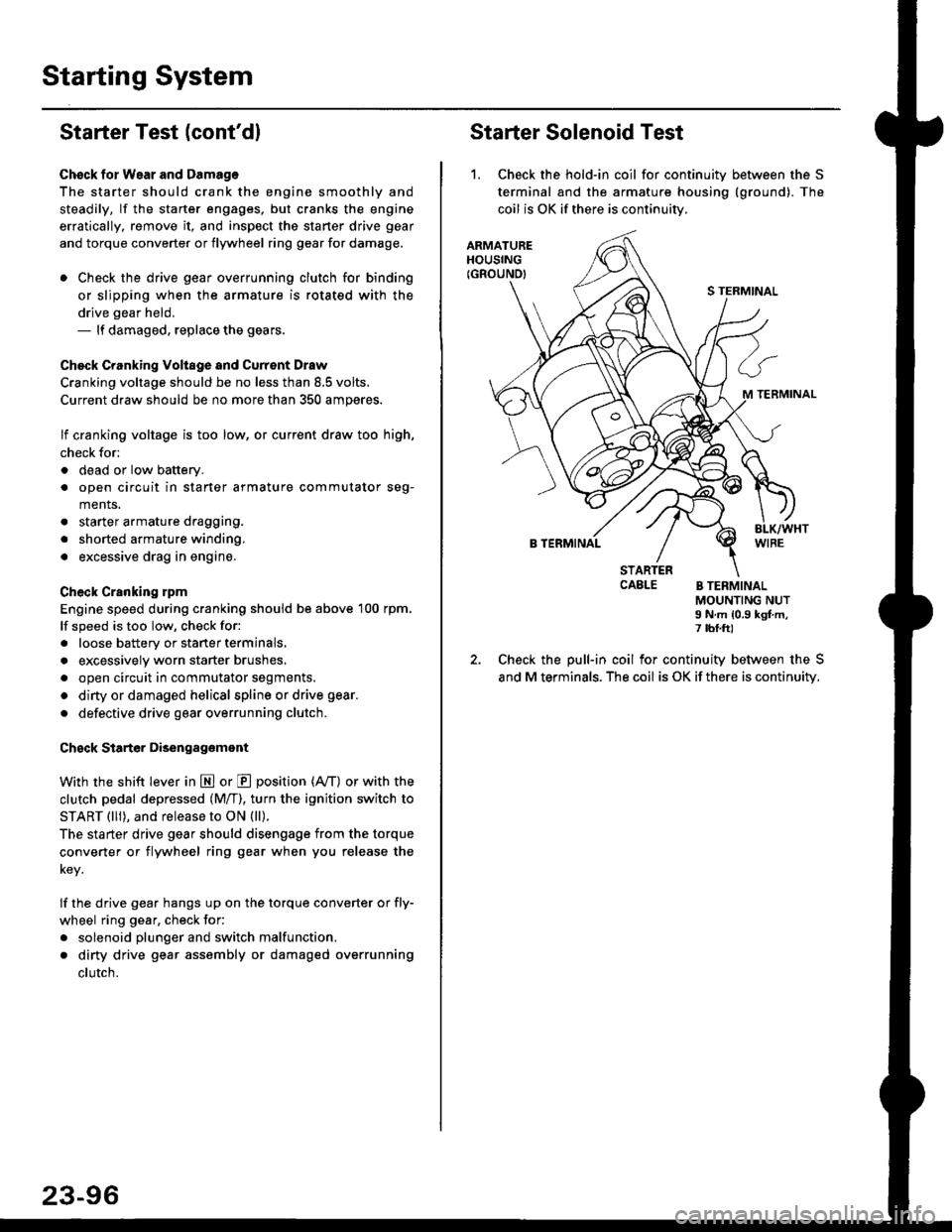
Starter Solenoid Test
1. Check the hold-in coil for continuitv between the S
terminal and the armature housing (ground). The
coil is OK if there is continuitv,
ARMATUREHOUSING(GROUND)
S TERMINAL
M TERMINAL
B TERMINAL
STARTERCAELE B TERMINALMOUNTING NUTI N.m {0.9 kgf.m,7 tbf.ft)
Check the pull-in coil for continuity between the S
and M terminals. The coil is OK if there is continuity.
Page 1569 of 2189

JBrush Holder Test
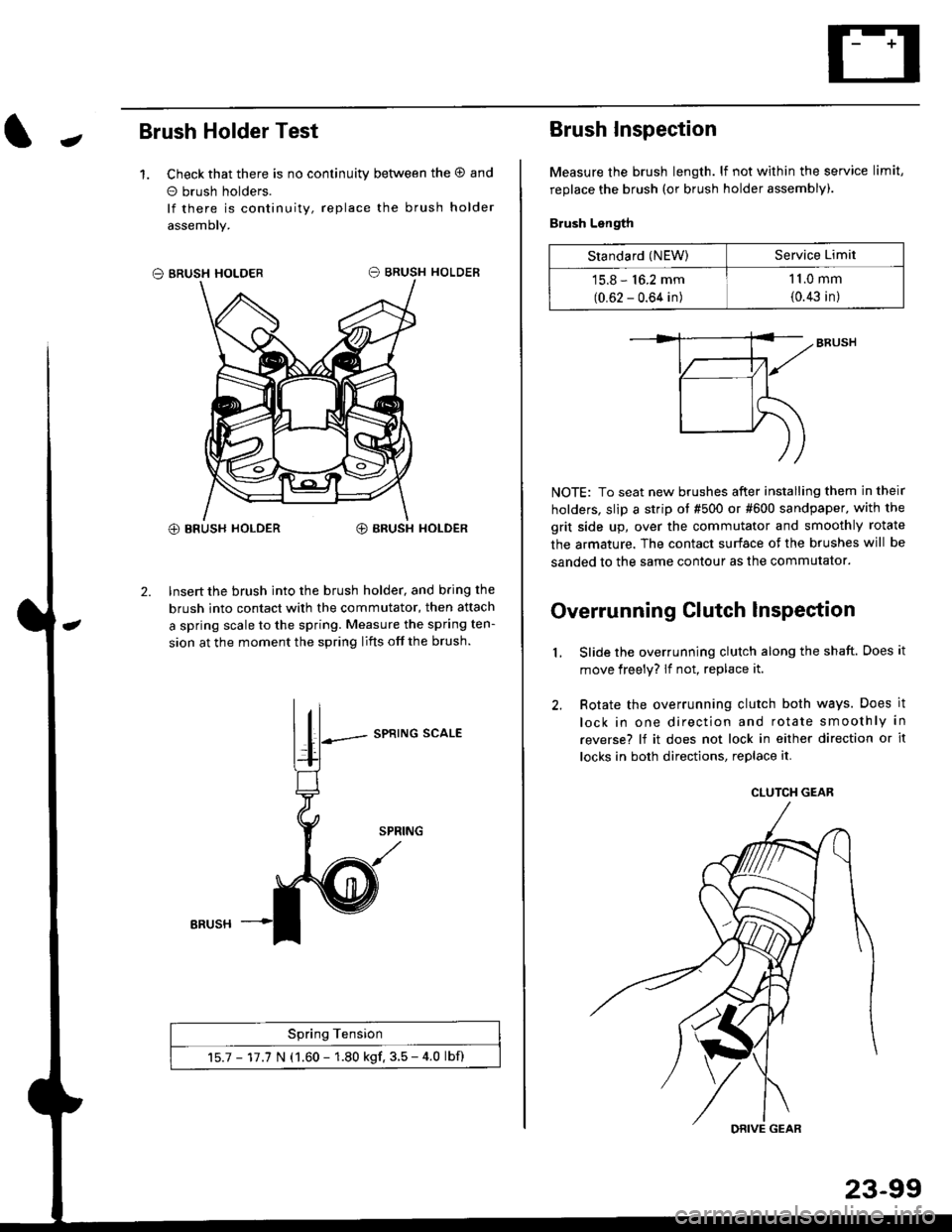
1. Check that there is no continuity between the O and
o brush holders.
lf there is continuity, replace the brush holder
assemoly.
O BRUSH HOLDER
@ BRUSH HOLDER€) BRUSH HOLDER
2. Insert the brush into the brush holder, and b.ing the
brush into contact with the commutator, then attach
a spring scale to the spring. Measure the spring ten-
sion at the moment the spring lifts off the brush.
SPRING SCALE
Spring Tension
15.7 - 17.7 N (1.60 - 1.80 kgf. 3.5 - 4.0 lbf)
ERUSH
Brush Inspection
Measure the brush length. lf not within the service limit,
replace the brush (or brush holder assembly).
Brush Length
NOTE: To seat new brushes after installing them in their
holders, slip a strip ot #500 or #600 sandpaper. with the
grit side up, over the commutator and smoothly rotate
the armature. The contact surface of the brushes will be
sanded to the same contour as the commutator.
Overrunning Clutch lnspection
Slide the overrunning clutch along the shaft. Does it
move freely? lf not, replace it.
Rotate the overrunning clutch both ways. Does it
lock in one direction and rotate smoothly in
reverse? lf it does not lock in either direction or it
locks in both directions, replace it.
2.
L
Standard (NEW)Service Limit
15.8 - 16.2 mm
(0.62 - 0.64 in)
1 1.0 mm
{0.43 in)
CLUTCH GEAR
DRIVE GEAR
Page 1708 of 2189
Moonroof
1.
Switch Test
Carefully remove the switch from the driver's dash-
board lower cover {see page 23-205}.
Check for continuitv between the terminals in each
switch position according to the table.
Terminal
t*',*-----__\I234
ut-t-
OPENo--o
CLOSEo---o
TILTo--o
23-234
Motor Test
'1.Remove the headliner (see section 20).
Disconnect the 2P connector from the moonroof
motor.
Terminal side of male terminals
Check the motor by connecting power and ground
according to the table.
4. lf the motor does not run, replace it (see section 20).
NOTE: See Closing Force Check in section 20 for
motor clutch test.
\_____lTr1
Position
,l
OPENo@
CLOSE@