1999 HONDA CIVIC Clutch
[x] Cancel search: ClutchPage 1014 of 2189
Transmission
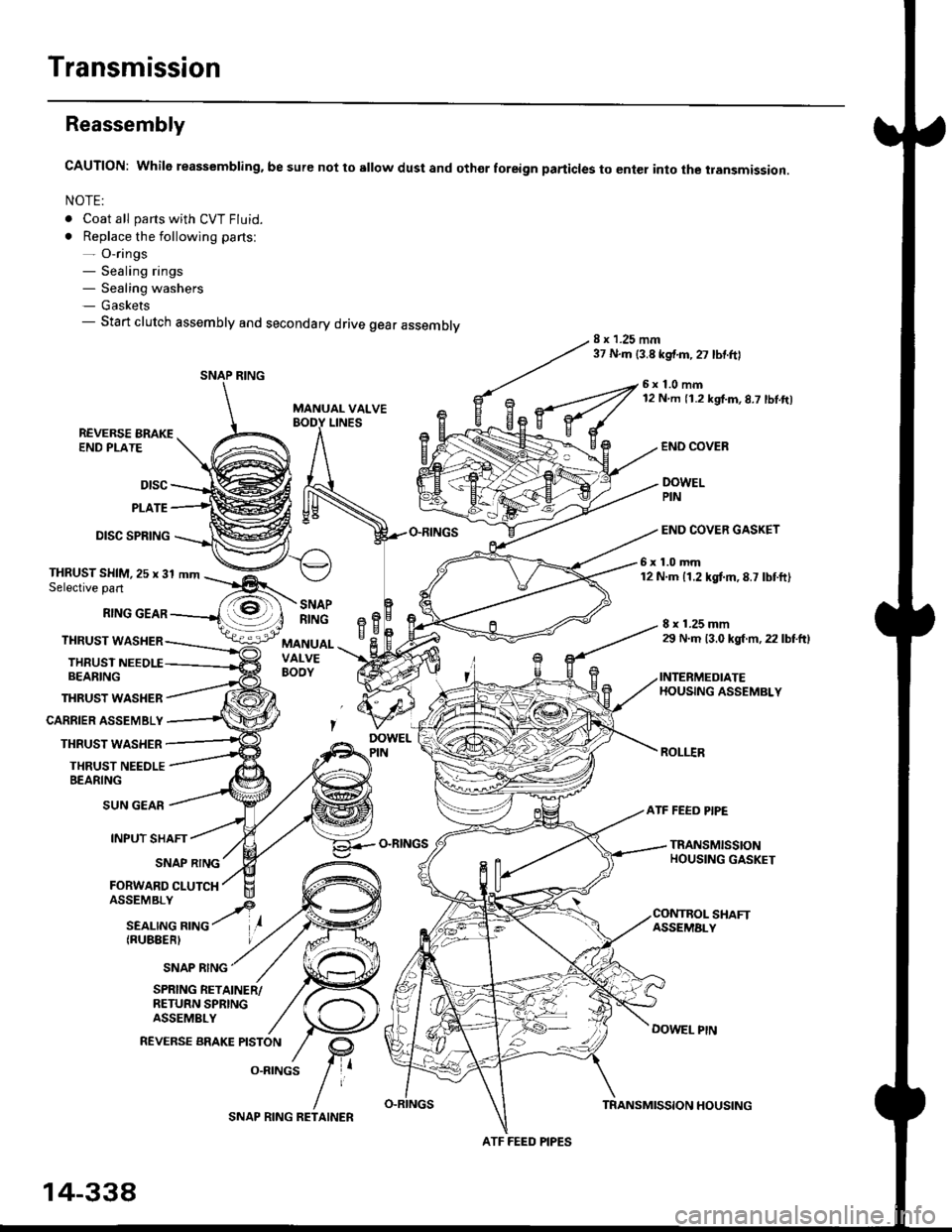
Reassembly
CAUTION: While reassembling. be sure not to sllow dust and othor foreign particles to enter into the transmission.
NOTE:
. Coat all parts with CVT Fluid.
. Replace the following parts:- O-rings- Sealing rings- Sealing washers- Gaskets- Start clutch assembly and secondary drive gear assembly8 x 1.25 mm37 N.m {3.8 kgf.m,27 lbtftl
MANUAL VALVE
6x1.0mm12 N m 11.2 kgf.m,8.7 lbl.ft)
LINESREVERSE BRAKEEND PLATE
Dtsc
PLATE
DISC SPRING
THRUST WASHER
CARRIER ASSEMBLY
THRUST WASHER
THRUST NEEDLEBEARING
END COVEB
DOWELPIN
END COVER GASKET
6x1.0mm12 N.m 11.2 kgtm,8.7 lbtft)THRUST SHIM,25 x 31 mmSelective part
RING GEAR
THRUST WASHER
THRUSTBEARING
8 x 1.25 mm29 N.m 13.0 kgl m, 22 lbtftl
INTERMEDIATEHOUSING ASSEMBLY
ROLI.IR
SNAPRINGeBH^cMANUALVALVEBOOY
SUN GEAR
INPUT SHAFT
(RUBEERI
ATF FEED PIPE
O-RINGSTRANSMISSIONHOUSING GASKETSNAP RING
FORWARD CLUTCH
SNAP RING
SHAFTASSEMALY
DOWEL PtN
SPRING RETAINER/RETURN SPRINGASSEMBLY
REVERSE BRAKE PISTON
O.RINGS
SNAP RING
ATF FEED PIPES
14-338
SNAP RING RETAINERTRANSMISSION HOUSING
Page 1016 of 2189
Transmission
16.
Reassembly (cont'dl
21.
17.
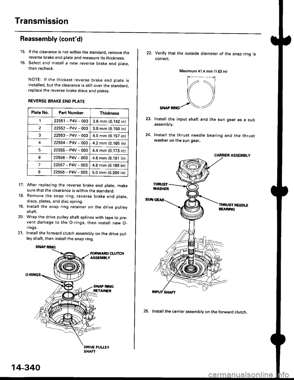
lf the clearance is not within the standard, remove thereverse brake end plate and measure its thickness.Select and install a new reverse brake end Dlate.then recheck.
NOTE: lf the thickest reverse brake end olate isinstalled, but the clearance is still over the standard,replace the reverse brake discs and plates.
REVERSE BRAKE END PLATE
After replacing the reverse brake end plate, makesure that the clearance is within the standard.Remove the snap ring, reverse brake end plate,
discs, plates. and disc spring.
Install the snap ring retainer on the drive pulley
shaft.
Wrap the drive pulley shaft splines with tape to pre-
vent damage to the O-rings, then install new O-n ngs.
Install the forward clutch assembly on the drive pul-
ley shaft, then installthe snap ring.
SITAP
O-RINGS
18.
19.
20.
SI{AP RIM;BETA EB
DRIVE PUI.IEYSHAFT
Plat6 No.Part NumberThickness
122551 - P4V - 0033.6 mm (0.142 in)
22552-P4V-0033.8 mm (0.150 in)
22553-P4V-0034.0 mm (0.157 in)
422554-P4V-0034.2 mm (0.165 in)
522555-P4V-0034.4 mm (0.173 in)
622556-P4V-0034.6 mm (0.181 in)
722557 -P4V -OO34.8 mm (0.189 in)
822558-P4V-0035.0 mm (0.200 in)
14-340
25. Installthe carrier assembly on the forward clutch.
22. Verity that the outside diameter ol the snap ring iscorrect.
SI{AP RIiIG
Install the input shaft and the sun gear as a subassemDry.
Install the th.ust needle bearing and the thrustwasher on the sun gear.
CARRIER ASSEMBLY
THFUST I'IEEDI!EEARIT{G
Msximum 41.4 mm 11.63 in)
IHruST
Page 1018 of 2189
Transmission
Reassembly (cont'd)
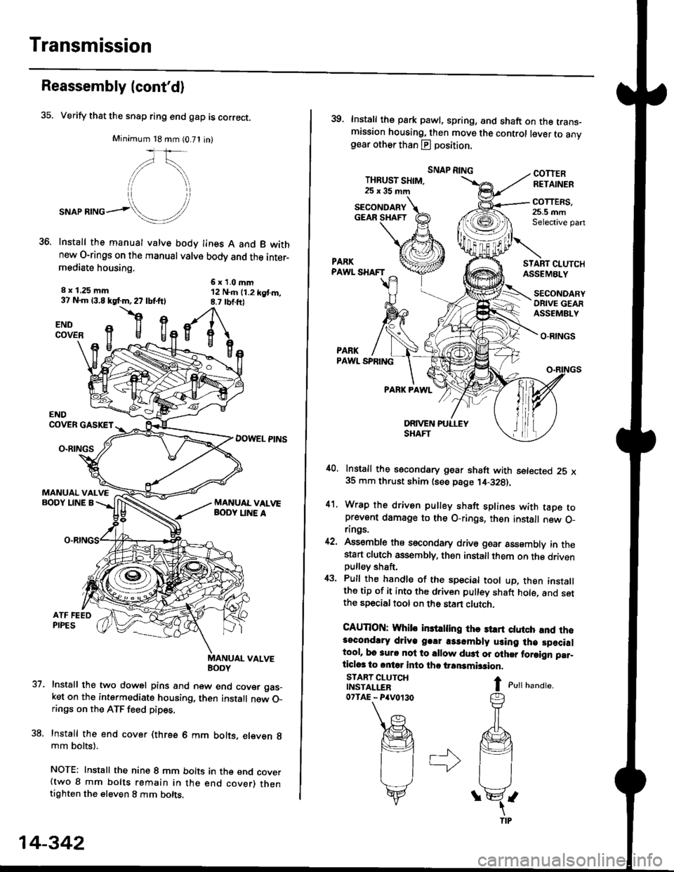
35. Verify that the snap ring end gap is correct.
Minimum 18 mm (0.71 in)
,/\,
."or**ol!/'
Install the manual valve body lines A and B wkhnew O-rings on the manual valve body and the inter-mediate housing.
6x1.0mm12 N..n (1.2 kgt m,8.7 rbtft)
8 x 1.25 mm37 N.m 13.8 kgf.m,27 lbf.ftl
flgENDCOVER
37.
ENDCOVER GASKET
DOWEL PINSO-RINGS
MANUAL VALVEBODY LINE A
uaNYuAL VALVE
Install the two dowel pins and new end cover gas_ket on the intermediate housing, then install new O_rings on the ATF feed pipes.
Install the end cover (three 6 mm bolts, eleven g
mm bolts).
NOTE: Install the nine 8 mm bolts in the end cover(two 8 mm bolts remain in the end cover) thentighten the eleven 8 mm bolts.
14-342
39. Install the park pawl, spring, and shaft on the trans-mission housing, then move the control lever to anvgear other than E position.
THBUST SHIM,25x35mm
SNAP RINGCOTTERRETAINER
COTTERS,25.5 mmSelective pan
START CI.UTCHASSEMBLY
O.RINGS
PARKPAWL SPRING
PARK PAWL
,10, Install the secondary gear shaft with setected 25 x35 mm thrust shim (see page ,14-328).
41. Wrap the driven pulley shaft splines with taDe toprevent damage to the O-rings, then install new O_rings.
42, Assemble ths secondary drive goar assembly in thestart clutch assembly, then installthem on the drivenpulley shaft,
43. Pull the handle of the special tool up, then installthe tip of it into the driven pulley shaft hole, and setthe special tool on the stan clutch.
CAUTION: Whib in3trling thc st rt ctutch and rh.3ocondlry driye g.!r a3sombly using lh€ specialtool, bo 3urc nol to sllow du3t or olher foraign par_ticlos to ontq into tho iransmbsion.
I c,rr r,unar".
SECONDARYGEAR SHAFT
START CLUTCHINSTALLER07TAE - P4V0r30
SECONDARYORIVE GEAFASSEMBLY
Page 1019 of 2189
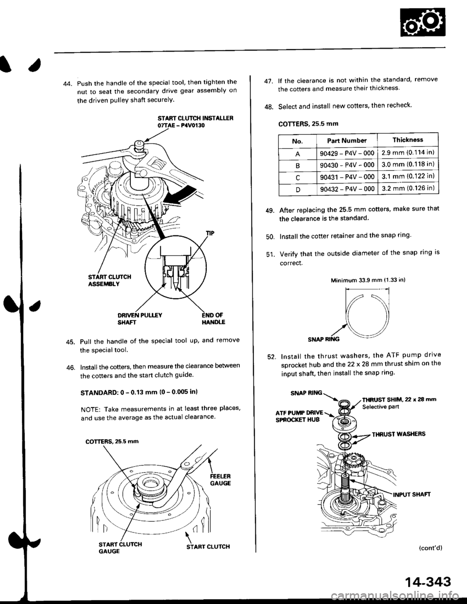
44. Push the handle of the special tool, then tighten the
nut to seal the secondary drive gear assembly on
the driven pulleY shaft securelY.
STAAT CLUTCH Ii'ISTALIIR07TAE - PaV0130
OF
46.
SHAFTHA'{DI,-E
Pull the handle of the special tool up, and remove
the special tool.
lnstallthe cotters, then measure the clearance Delween
the cotters and the start clutch guide
STANDARD: 0 - 0.13 mm (0 - 0.005 inl
NOTE: Take measurements in at least three places,
and use the average as the actual clearance
GAUGE
lil(il
COTTERS, 25.5 mm
START 1
GAUGCSTART CLUTCH
14-343
47.
48.
lf the clearance is not within the standard, remove
the cotters and measure their thickness
Select and install new cotters, then recheck.
COTTERS, 25.5 mm
After replacing the 25.5 mm cotters, make sure that
the clearance is the standard
lnstall the cotter retainer and the snap rlng
Verify that the outside diameter of the snap ring is
correct.
Minimum 33.9 mm (1.33 in)
SNAP RII{G
lnstall the thrust washers. the ATF pump drrve
sprocket hub and the 22 x 28 mm thrust shim on the
inDUt shaft, then install the snap ring.
49.
50.
52.
THRUST WASXERS
INPUT SHAFT
(cont'd)
No.Part NumberThickness
90429-P4V-0002.9mm(0.114 in)
B90430-P4V-0003.0mm(0.118 in)
c90431 -P4V-0003.1 mm (0.122 ln)
D90432-P4V-0003.2 mm (0.126 in)
SNAPRING\
ATF PUMP DRIVESPROCKET HUB
THFUST SHIM, 22 x 2a mm
Selective pan
Page 1027 of 2189

22. Install the shift cable end on the control lever, and
install the shift cable on the shift cable bracket'
CAUTION: Take care not to bend the shift cable'
23. lnstall the clip in the direction shown.
LOCKNUT
SHIFI CABLE 29 N m {3.0 kg{ m, 22lblftl
SHIFT CABLEERACKET
WASHERIPLASTIC)
CONTROL LEVER
24, Connect the solenoid harness connector. the drive
pulley speed sensor connector. and the ground
cable terminals.
6x1.0mm12 N.m {1.2 kgf.m.8,7 rbtft)
GROUND CABLETERMINAL 6x1.0mm
GROUNDTERMINAL
12 N.m {1.2 kgf'm,8.7lbtfrl
DRIVE PULLEYSPEED SENSORCONNECTOR
SOLENOID HARNESS
CONNECTOR
25. Connect the starter motor cable on the starter motor.
and install the cable holder.
NOTE: When installing the staner motor cable. make
sure that the crimped side of the ring terminal is
facing out (see section 23).
STARTEB
BMOUNTING NUT
9 N.m (0.9 kgf m,7 lbf ft)
26. Install all removed connectors and clamps'
27. Install the distributor.
28. Install the intake air duct and air cleaner housing
29.
assemDly.
Refill the transmission with the recommended
Genuine Honda CVT Fluid (see page 14-2991
CAUTION: While filling the CvT Fluid, bs surs not io
allow dust and other fotoign particles to entor into
the transmission.
Connect the battery positive (+) terminal first, then
the negative (-l terminal to the battery'
Check the ignition timing (see section 23).
Start the engine. Set the parking brake, and shift the
transmission through all gears three times Check
shift cable adjustment (see page 14-355).
Check the front wheel alignment (see section 18)
Let the engine reach operating temperature (the
radiator fan comes on) with the transmission in lXl
or E position, then turn it off and check fluid level'
Perform the start clutch calibration procedure on
page 14-293.
Road test as described on pages 14-296 and 14-297
30.
31.
34.
36.
STARTER MOTOR
14-351
Page 1281 of 2189
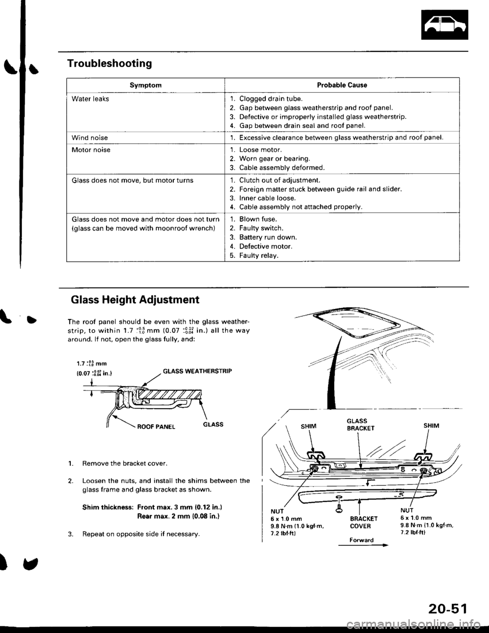
Troubleshooting
SymptomProbable Cause
Water leaks1. Clogged drain tube.
2. Gap between glass weatherstrjp and roof panel.
3. Defective or improperly installed glass weatherstrip.
4. Gap between drain seal and roof panel.
Wind noise'1. Excessive clearance between glass weatherstrip and roof panel.
Motor noise1. Loose motor.
2. Worn gear or bearing.
3. Cable assembly deformed.
Glass does not move, but motor turns'1. Clutch out of adjustment.
2. Foreign matter stuck between guide rail and slider.
3. lnner cable loose.
4. Cable assembly not attached properly.
Glass does not move and motor does not turn
{glass can be moved with moonroof wrench)
1. Blown fuse,
2. Faulty switch.
3. Battery run down.
4. Defective motor.
5. Faulty relay.
D
Glass Height Adjustment
The roof panel should be even with the glass weather-
strip, to within 1.7 :lr3 mm (0.07 :3:31 in.) all the way
around. lf not, open the giass fully, and:
GLASS WEATHERSTRIP
1. Remove the bracket cover.
Loosen the nuts, and install the shims between the
glass frame and glass bracket as shown.
Shim thickness: Front max.3 mm 10,12 in.l
Rear max. 2 mm 10.08 in.)
Repeat on opposite side i{ necessary.
)
5x1.0mm9.8 N.m 11.0 kgf m,7.2 rbtft)
SRACKETCOVEB
----------1>
6x1.0mm9.8 N.m {1.0 kgtm,7.2 tbf.ft)
1.7 tl.8 mm
{0.07 :3 3i in.}
20-51
Page 1287 of 2189
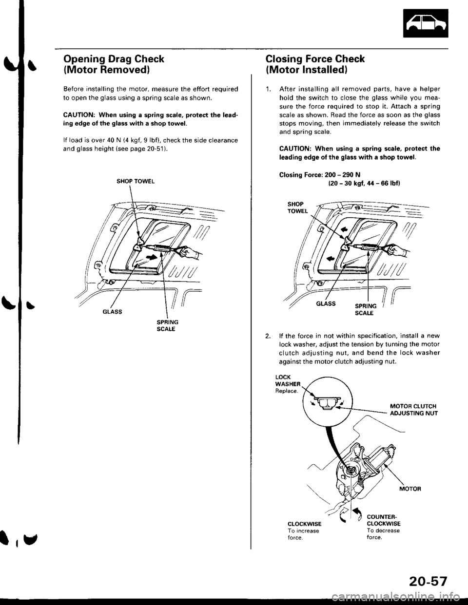
Opening Drag Check
{Motor Removed)
Before installing the motor, measure lhe effort required
to open the glass using a spring scale as shown.
CAUTION: When using a spring scale, pfotest the lead-
ing edge ol the glass with a shop towel.
lf load is over 40 N (4 kgf,9 lbf), check the side clearance
and glass height (see page 20-51).
SHOP TOWEL
l,e
20-57
Closing Force Check
(Motor Installedl
'1. After installing all removed parts, have a helper
hold the switch to close the glass while you mea-
sure the force required to stop it. Attach a spring
scale as shown. Read the force as soon as the glass
stops moving, then immediately release the switch
and spring scale.
CAUTION: When using a spring scale, protect the
lerding edge ol the glass with a shop towel.
Closing Force: 200 - 290 N(20 - 30 kst, 44 - 66 lbfl
lf the torce in not within specification, install a new
lock washer, adjust the tension by turnang the motor
clutch adjusting nut, and bend the lock washer
against the motor clutch adjusting nut.
LOCKWASHERReplace.
COUNTER.cLocKwrsETo decrease
SCALE
Page 1425 of 2189
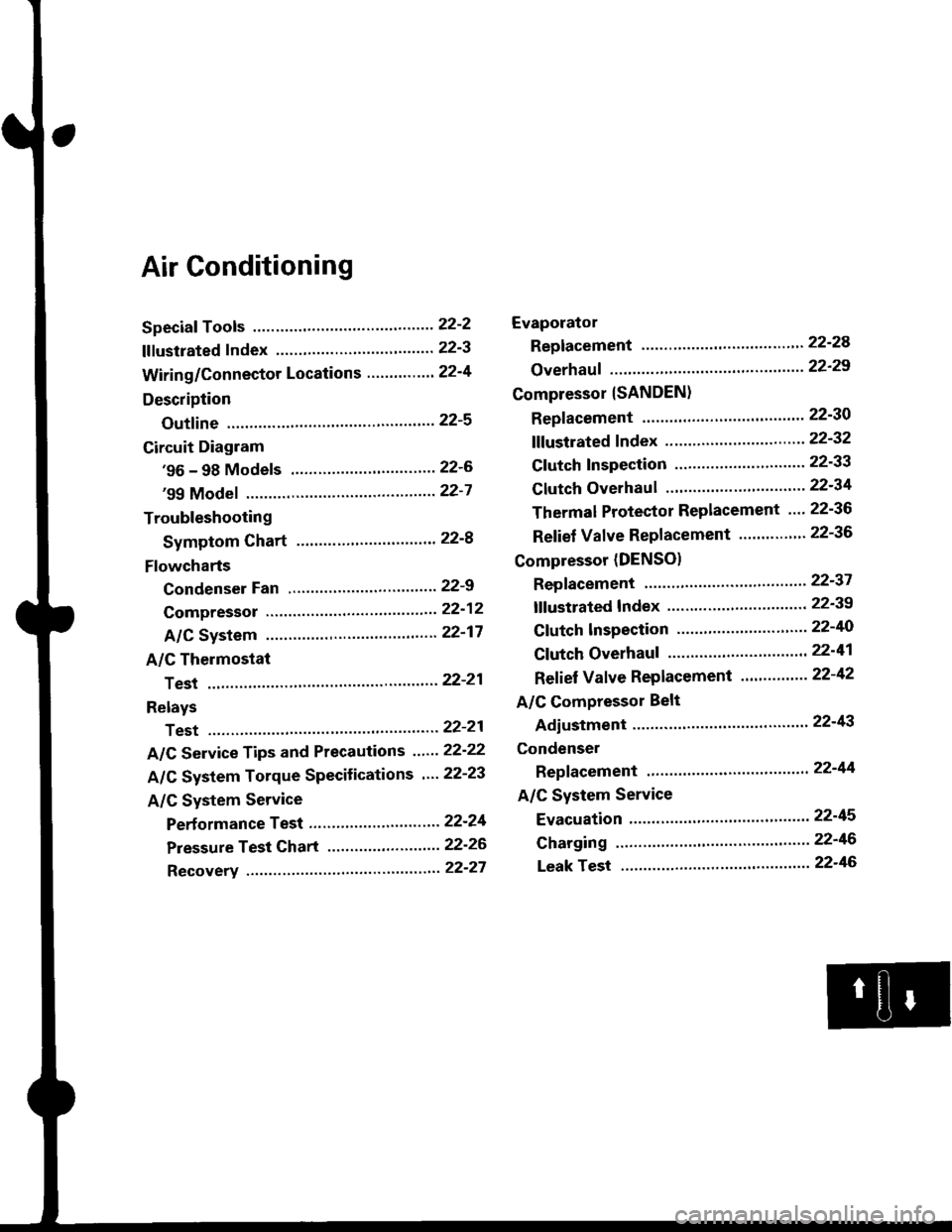
Air Conditioning
Speciaf Tools ......'.....' 22-2
f f f ustrated f ndex ......................... ".......' 22-3
Wiring/Connector Locations'.........'.... 22'4
Description
Outfine ............ .......22-s
Circuit Diagram
'96 - 98 Models ......"..........".......'.... 22-6
'99 Modef """""""' 22-7
Troubleshooting
Symptom Chart ".'......""................. 22-8
Flowcharts
Condenser Fan .........".................,..'. 22-9
Compressor .....""" 22-12
A/C System .........'.22'17
A/C Thermostat
Test ........'.......' """'22'21
Relays
Test ....."'......... ..""'22-21
A/C Service Tips and Precautions ......22-22
A/C System Torque Specifications '...22-23
A/C System Service
Performance Test ... '."......... ".... ....'..22-24
Pressure Test Chart .................. .... "' 22-26
Recovery ...".........," 22-27
Evaporator
Replacement .....",' 22'24
Overhauf .....-.....""' 22'29
Compressor {SANDEN}
Repf acement ......'.' 22-30
fffustrated fndex ......"..................'.... 22'32
Cf utch Inspection ......... "............ ...... 22-33
Clutch Overhau I ........................ ....... 22-34
Thermal Protector Replacement .... 22-36
Relief Valve Replacement ......'..."". 22-36
Compressor (DENSO)
Repfacement ..""',' 22-37
lf lustrated Index ............................... 22-39
Clutch lnspection ............."'...... "'.... 22-40
Cf utch Overhaul .....................'......... 22-41
Ref ief Valve Replacement'..'......"'.. 22-42
A/C Compressor Belt
Adiustment ............22'43
Condenser
Repfacement .......,,22'44
A/C System Service
Evacuation ...,,,.......22-45
Charging '..........--'..22'46
Leak rest """""""'22-46