Page 1544 of 2189

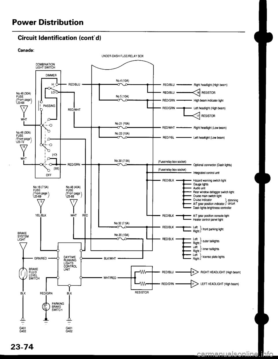
Power Distribution
Circuit ldentification (cont'd)
Canada:
COMBINATIONLIGHT SWITCH
N0.48 {30A)
RED/BLU - Right headlighl (High boam)
FEDiBLU ----< REstsTOR
REo/GRN - HiJh beam indicator lighl
BEo/GRN - Left headlighl iH,gh beam)
L
Fight headlight {Low beam)
FEo/YEL - L€ll headlight (Low beam)
(Fuse/lelay box sockel)Optional conneclor (oash lighs)
Inleg6led conlrcl unil
- Hazard wanirE swilch lighl
i- Gauge lEhts
l- Audio unil
l- Re& Yrindow delogg8r swili
t- Ctuise main swrdr ligh
l- C/uise indEator l
E g"ffiry:'l,:1':::1
Refi window delog$r swildr light
Ctuise indicalor 1 dimming,T geal posilion indicator J circu(Dasn lghls brignmess co oller
BRAKESYSTEMLIGHT
V
I
l- GFf
,,4,,0*,lf tIFLUDII ,j I LEVEL
Y
SWTCH
I8LKI
I
I
I:
G401G402
REo/BLK - l/T ged position console lqhl- Hqalor codrot panel tighl
REO/BLK -F- Lefi ) .l- g;n1J lron 9arrn! qm
FEDiBLK + Letl I
F Rqn J ouer larrqns
- I Al, I
{- i'-;*; inne' raittiotts
E fifi]t'"nt"o't't'sn"
*ro,rru -$ RcHT HEADLIGHT (Hrgh beam)
BEDiGRN -+ LEFI H EADLIGHT (High beam)
I BLK
IIPARKING IEFAKE IswrrcH I
I:
G401G402
UNDER,DASH FUSE/RELAY 8OX
lo| | PASSTNGto
/Fforn page\\a-68 l
N0.48 {304)FUSE/From page\\23-72 )
N0.18 (7.54)FUSE/From page \\?3-69 J
v
YIYEUBLK
N0.48 (40A)FUSE/From paqe \\23-68 - ,/
RED6RN
23-74
Page 1549 of 2189

t
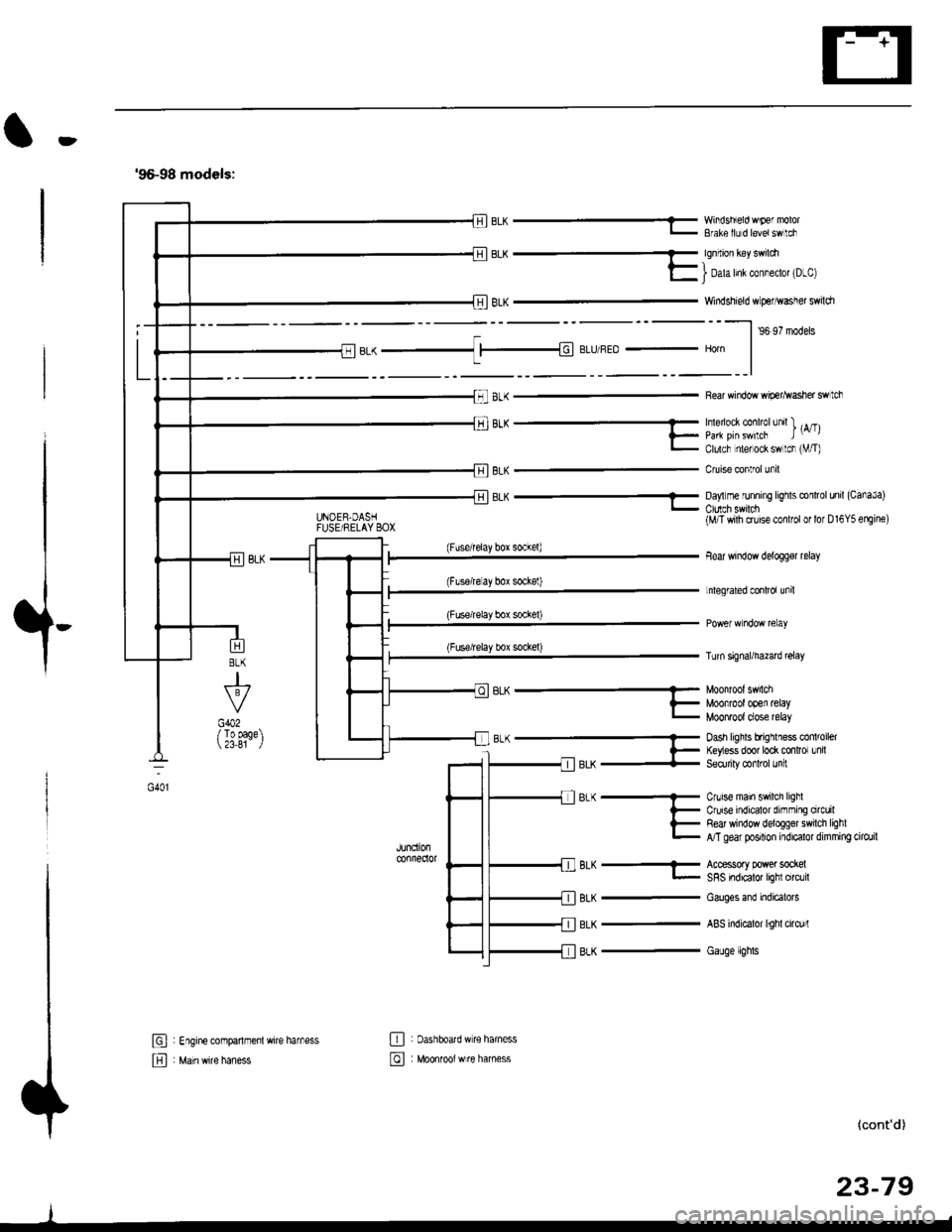
'96-98 models:
BLK -..1 |-|d BLIJ/REo - Horn
8LK
J
G402/ To page 23,81
6L^ --...........-- Munn'un' 5.nLi
?_ Moofrootooen retayL MOOnTOOI dose relay
B-(- Dash hghls bfrqrlless co 'oel
l- ftyess door to* mnlror Lnil-llerX + Seorriry @rl'ol Jn :
JUndonconnedor
BLK
BLK
BLK
Cnrise main swilch lighlCruise indicalor dirnming orcuilRed window deloggel swilch lighlA/T gear posilion indicalor dimming cilo./il
Accessory power sockelSRS indicalor lighl circlil
Cauges end indicatols
ABS indicalor lighl cirq)rl
Gauge lights
El : Engine companmenl wire harness
E , M"in *it" h"n"..
E : oashboatd w€ haness
@ : Moonrool w re harness
UNOEB,DASHFUSE/RELAY BOX
EL^ - YY'iisnEo 'F€ "'v'u'- Bfale llJ d levetswlci
qq.-_
E I Dah Inl col"eclot 'D-cl
Windshield w perhvasher swildr
--l ,o ,? '.da.
Rear window wip€r^vasher swtch
'''"_- -- , rA/Tll_ paa pirswilcF t-,l- Clulcf nlel ock sw lcr rVT)
Cruise conlrol unil
8LK - Da,'lm€ runnrng lrghts conltol unil (CanaJa)
(Fuserelay box sockel)
(Flserelay bor sockel)
(Fuse/relay box socke0
(Fuse/relay box sockel)
BLK-
(M/T wilh cruise conlfol or lor D16Y5 erEine)
Bear window delogger relay
Lnlegrated conlrol unil
Turn signal/hazad @lay
(cont'd)
23-79
oot
Page 1552 of 2189
Ground Distribution
Circuit ldentification (cont'dl
'99-00 models:(Wilholl ABS)
r'1BL( -< 6 | c40. tFror oaoe 23-BC. II
L
E
UNDEF.H@DFUSF]RELAY BOX
_::I
A,/I gefi posilion swilchELD unil
Servi@ check connector
BL-_14BL- rl--{ry--Browe,mororreray
L4 ,r^ -.;--a-r,* -11-51 BLK - Hearer conrror o6nt n"*-fi-+aLx-lfuBLK- Hearer conrror panel
eLx -iff BLK - ff;?,m",:[:' "n'
or*
ABS glmp motor
_trl
G501
Pos€r door lock cortaol unitDivers door lock aclualorDriver's door lock switchLefl miror delogger
BLK --.+t _
F J Power wndos man swdch
-. Dive/s Fo*gr window motor
TBLK -.1 F--{ BLK - Fighr.niror detogger
tr
tr
E : Healer sub-haness A
El : Healer sub'harress B
: Floor wire hamess
: Drve/sdoorwife haness
-
|,-"*T-"^tl I
vl-L"."
G551
ort,
El ' Main *it" hanes
E : Dashboafd wirc harness
23-82
@ Passenger's doof w're hamess
Page 1556 of 2189
Power Relays
Relay Test
Turn Signal/Hazard Relay:
See page 23-172
Normally-open type:
1. Check for continuity between the terminals.. There should be continujty between the No. 1 andNo.3 terminals when power and ground are con-nected to the No. 2 and No. 4 terminals.. There should be no continuity between the No. 1and No. 3 terminals when power is disconnected.
3
. Blower motor relay
. ABS pump motor relay
Terminal
-i*rt"r-*or\13
Disconnected
Connectedo
,I IIY F>rr €,?I
23-86
. Rear window defogger relay
Starter cut relayt '96 - 97 models
Horn relayi '96 97 models
Blower motor high relay: '99 - 0O mooersa
Page 1557 of 2189
Normally-opsn tYPe:
1. Check for continuity between the terminals
. There should be continuity between the No. 1 and
No. 2 terminals when power and ground are con-
nected to the No. 3 and No 4terminals.
o There should be no continuity between the No 1
and No.2 terminals when power is disconnected'
Terminal
Power iNo.3 - No,4) \
I2
Disconnected
Connectedoo
a
a
a
Power window relaY
Radiator fan relaY
Condenser fan relaY
A/C compressor clutch relaY
Starter cut relay: '98 - 00 models
Horn relay: '98 - 00 models
Five-ierminal type:
1. Check for continuitv between the terminals.
. There should be continuity betlveen the No. 1 and
No. 2 terminals when power and ground are con-
nected to the No. 3 and No 5terminals.
. There should be continuity between the No 2 and
No. 4 terminals when power is disconnected'
--1
I
II
t
Moonroof open relay: '96 - 97 models
Moonroof close relay: '96 - 97 models
(cont'd)
23-87
Terminal
Power (No. 3 - No. 5)\
4
Disconnectedo--o
Connectedo--o
Page 1558 of 2189
Power Relays
Relay Test (cont'd)
Five-terminsl type:
l. Check for continuity between the terminals.
. There should be continuity between the No. 1and No, 2 terminals when power and ground areconnected to the No. 5 and No. 3 terminals.o There should be continuity between the No. 1and No. 4 terminals when power is disconnected.
. Moonroof open relay: '98-00models
. Moonroof close relay: '98 - 00 mooets
Terminal
P"*"r{ltl"5-N".3)-\14
Disco n n ectedo----o
Connectedo-----o
23-88
Page 1617 of 2189

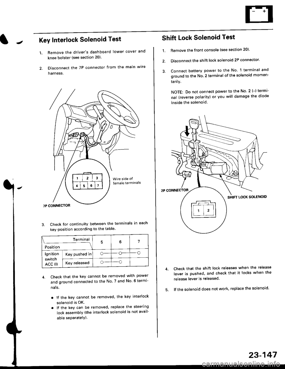
Key Interlock Solenoid Test
Remove the driver's dashboard lower cover and
knee bolster (see section 20)
Disconnect the 7P connector from the main w're
harness.
3. Check Ior continuity between the terminals in each
kev oosition according to the table'
4. Check that the key cannot be removed with power
and ground connected to the No. 7 and No 6 termi-
nals
. lf the key cannot be removed. the key interlock
solenoid is OK.
. lf the key can be removed, replace the steering
lock assembly (the interlock solenoid is not avail-
able seParatelY).
1.
Terminal
i*i,r"
- - --\7
lgnition
switch
ACC fl)
Key pushed ino--o
Key releasedo--o
Shift Lock Solenoid Test
't.Remove ths front console (see section 20)'
Disconnect the shift lock solenoid 2P connector'
Connect battery power to the No. 1 terminal and
ground to the No. 2 terminal of the solenoid momen-
Iarrry.
NOTE: Do not connect power to the No 2(-) termi-
nal (reverse polarity) or you will damage the diode
inside the solenoid
Check that the shift lock releases when the release
lever is pushed, and check that it locks when the
release lever is released
lf the solenoid does not work, replace the solenoid'
23-147
Page 1637 of 2189

Headlights/Front Turn
Signal/Parking Lights
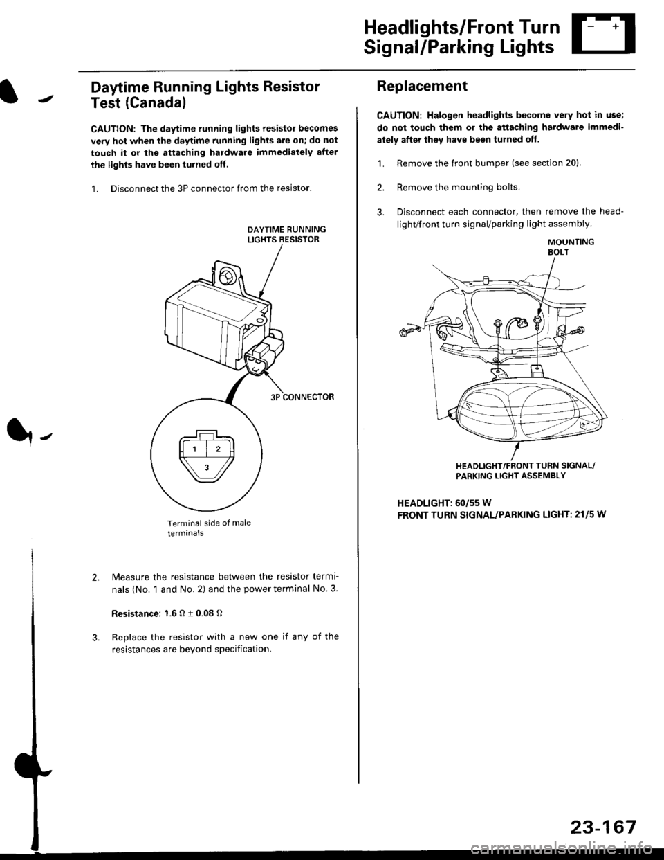
Daytime Running Lights Resistor
Test (Canada)
CAUTION: The daytime running lights resistor becomes
very hot when the daytime running lights are on; do not
touch il or the attaching hardware immediately after
the lights have been iurned off.
1. Disconnect the 3P connector from the resistor.
Terminal side of male
terminals
N4easure the resistance between the resistor termi
nals (No. 1 and No. 2) and the power terminal No. 3.
Resistance: 1.6 O t 0.08 O
Replace the resistor with a new one if any of the
resistances are beyond specification.
It-
Replacement
CAUTION: Halogen headlights b€come very hot in use;
do not touch them or the attaching hardware immedi-
ately after they have been turned off.
1. Remove the front bumper (see section 20).
2. Remove the mounting bolts,
3. Disconnect each connector, then remove the head-
lighVfront turn signal/parking light assembly.
MOUNTINGEOLT
HEADLIGHT/FRONT TUFN SIGNAL/PARKING LIGHT ASSEMBLY
HEADLIGHT: 60/55 W
FRONT TURN SIGNAL/PARKING LIGHT: 21l5 w
23-167