1999 HONDA CIVIC ABS
[x] Cancel search: ABSPage 2039 of 2189
rl,
;
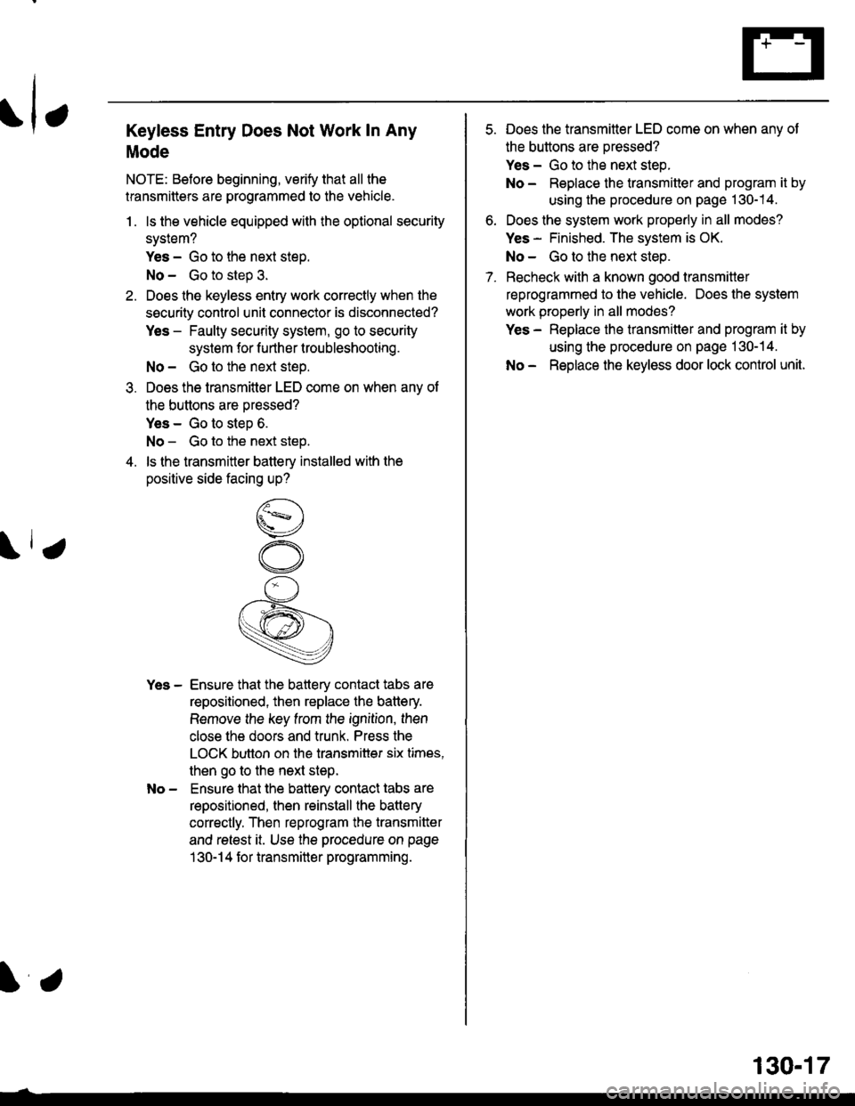
Keyless Entry Does Not Work ln Any
Mode
NOTE: Before beginning, verify that all the
transmitters are programmed to the vehicle.
1. ls the vehicle equipped with the optional security
system?
Yes - Go to the next steD.
No - Go to step 3.
2. Does lhe keyless entry work correctly when the
security control unit connector is disconnected?
Yes - Faulty security system, go to security
system for f urther lroubleshooting.
No - Go to the next steo.
3. Does the transmitter LED come on when anv of
the buttons are pressed?
Yes - Go to step 6.
No - Go to the next step.
4. ls the transmitter battery installed with the
positive side facing up?
Yes - Ensure that the battery contact tabs are
repositioned, then replace the battery.
Remove the key trom the ignition, then
close the doors and trunk. Press the
LOCK button on the transmitter six times,
then go to the next step.
No - Ensure that the battery contact tabs are
repositioned, then reinstall the battery
correctly. Then reprogram the transmitter
and retest it. Use the procedure on page
1 30-1 4 for transmitter programming.
130-17
7.
Does the transmitter LED come on when anv of
the buttons are oressed?
Yes - Go to the next steo.
No - Replace the transmitter and program it by
using the procedure on page 130-14.
Does the system work properly in all modes?
Yes - Finished. The system is OK.
No - Go to the next step.
Recheck with a known good transmitter
reprogrammed to the vehicle. Does the system
work properly in all modes?
Yes - Replace the transmitter and program it by
using the procedure on page 130-14.
No - Replace the keyless door lock control unit.
Page 2108 of 2189
-
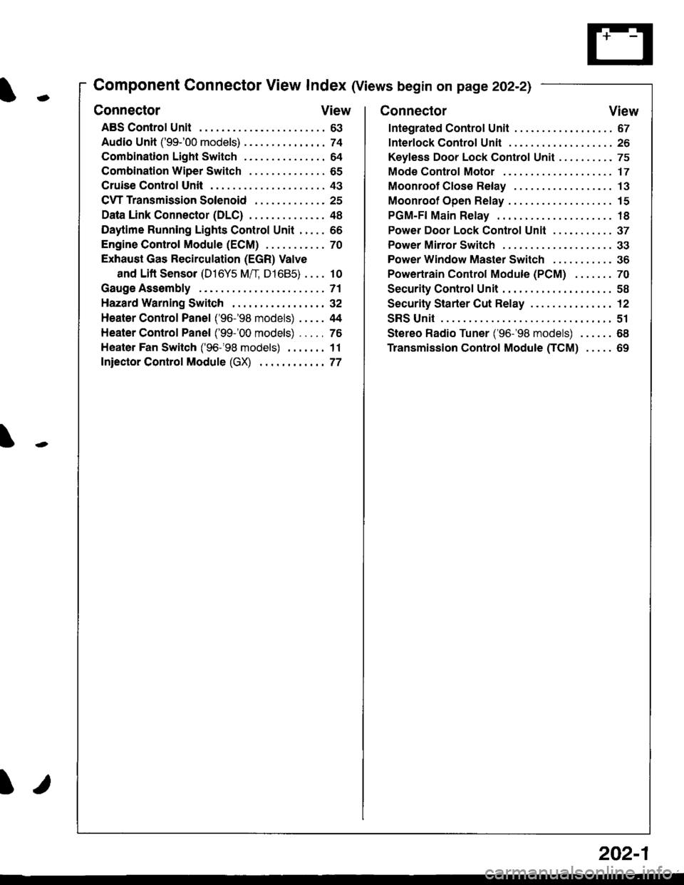
Component Connector View Index (Views begin on page 202-21
Connector View
ABS Control Unit........ ......63
Audio Unit ('99-'00 models) ......74
Combination Light Switch . . . . . . . . . . . . . . . 64
Combination Wiper Switch . . . . . . . . . . . . . . 65
Cruise Control Unit.... .....43
C\TTTransmission Solenoid ............. 25
Data Link Connector (DLC) ..... 48
Daytime Runnlng Lights Control Unit ..... 66
Engine control Module (ECM) ...........70
Exhaust Gas Recirculation (EGR) Valve
and Lift Sensor (D16Y5 Mfl, D1685) . . . . 10
Gauge Assembly .............71
HazardWarnlngSwitch,,. .,,,...,,,,... 32
Heater Control Panel ('96-'98 models) .....44
Heater Control Panel ('99-'00 models) ...., 76
Heater Fan Switch ('96-'98 models) ,,,.... 11
fniector Control Module (GX) ............77
I/
202-1
Connector View
Integrated Control Unit .......,. 67
f nterfock Control Unit .... ...... 26
Keyfess Door Lock Control Unit . . . . , . . . . . 75
Mode Control Motor ... ........'17
Moonroof Close Relay .. .......13
Moonroof Open Relay ... .......15
PGM-FI Main Relay .. .......... 18
Power Door Lock Conlrol Unil ..... ...... 37
Power Mirror Switch .,... ...... 33
Power Window Master Switch .,.........36
Powertrain Control Module (PCM) .......70
Security Control Unit ..., ..,,... 58
Security Starter Cut Belay ... ...,,,....,, 12
SRS Unit ............. 51
Stereo Radio Tuner ('96-'98 models) ...... 68
Transmission Control Module CICM) .....69
Page 2115 of 2189
Connector Views (cont'd)
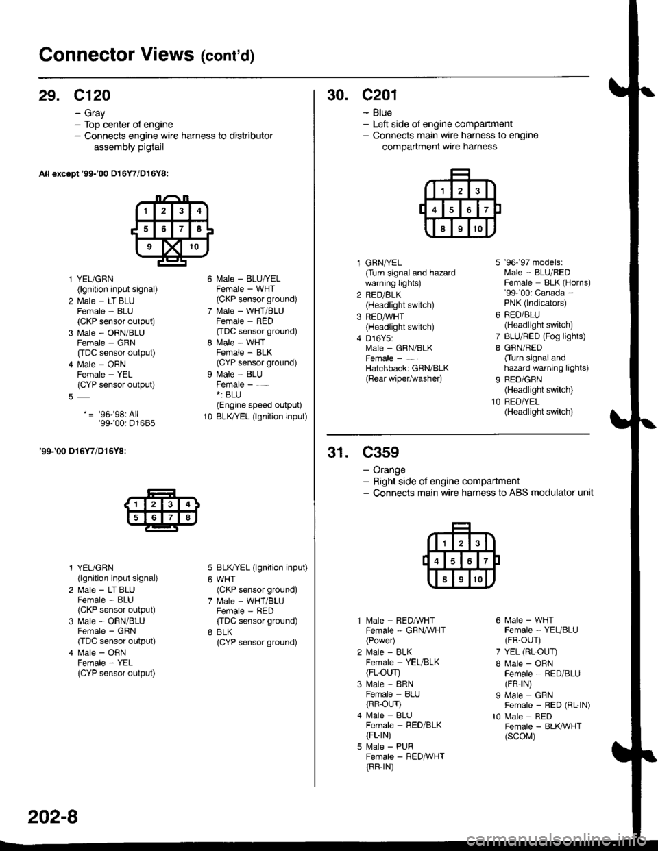
29. C120
- Gray- Top center of engine- Connects engine wire harness to distributor
assembly pigtail
All except '99-'00 016Y7/D16Y8:
l YEUGRN(lgnition input signal)
2 l\.4ale - LT BLUFemale - BLU(CKP sensor output)
3 Male - ORN/BLUFemale - GRN
[tDC sensor output)
4 l\.4ale - ORNFemale - YEL(CYP sensor output)
-= '96j98: All'99100: D1685
'99-'00 016Y7/D16Y8:
l YEUGRN(lgnition input signal)
2 Male - LT BLUFemale - BLU(CKP sensor output)
3 Male - ORN/BLUFemale - GRN
CIDC sensor output)
4 Male - ORNFemale - YEL
{CYP sensor output)
l\4ale - BLU/YELFemale - WHT(CKP sensor ground)
l\.4ale - WHT/BLUFCMAIE _ HtsL'(TDC sensor ground)
l\4ale - WHTFemale - BLK(CYP sensor ground)
Male - BLUFemale - . -*: BLU(Engine speed output)
BLK/YEL (lgnition input)
BLK/YEL (lgnition input)
WHT(CKP sensor ground)
Male - WHT/BLUFemale - RED
ffDC sensor ground)
BLK(CYP sensor ground)
10
202-8
30. c201
- Blue- Left side of engine compartment- Connects main wire harness to engine
compartment wire harness
l GRNA/EL(Turn signal and hazardwarning lights)
2 RED/BLK(Headlight switch)
3 REDAVHT(Headlight switch)
4 D16Y5:Male - GRN/BLKFemale -
Hatchbacki GRN/BLK
{Bear wipetwashe0
7
I
9b- 9/ mooets:lvlale - BLU/REDFemale BLK (Horns)'99-'00: Canada -
PNK (lndicators)
RED/BLU(Headlight switch)
BLU/RED (Fog lights)
GRN/RED
Cturn signal andhazard warning lights)
BED/GRN(Headlight switch)
RED/YEL(Headlight switch)
31. C359
- Orange- Right side ot engine compartment- Connects main wire harness to ABS modulator unit
10
l\4ale - REDAVHTFemale - GRNA/VHT(Power)
l\,4ale - BLKFemale - YEVBLK(FL-OUr)
Male - 8RNFemale BLIJ
{RR-OLrr)l\4ale BLUFemale - RED/BLK(FL-rN)
Male - PURFemale - RED&VHT(RR-rN)
6 Male - WHTFemale - YEUBLU(FR-OUr)
7 YEL (RL-OUr)
I Male - ORNFemale - RED/BLU(FR rN)
I Male GRNFemale - RED (RL-|N)
10 Male REDFemale - BLK,ryVHT(scol\,1)
Page 2122 of 2189
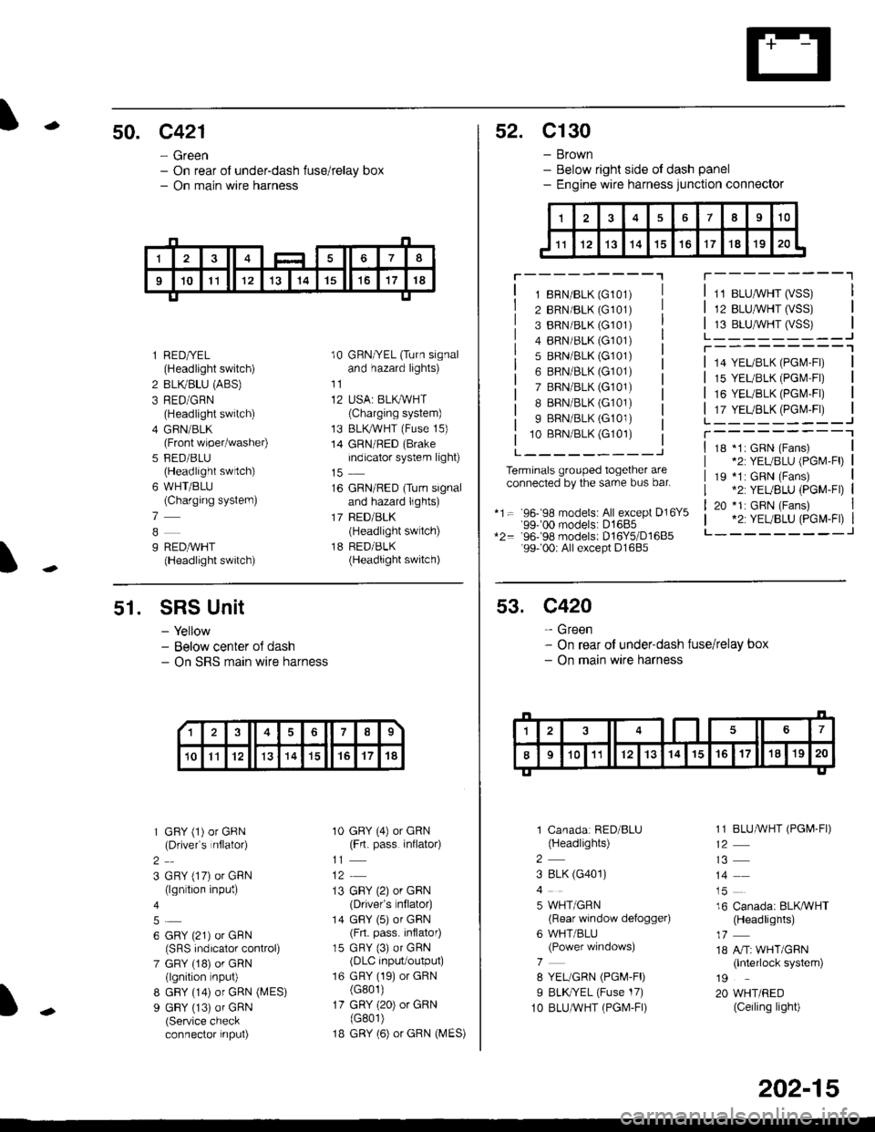
-50. c421
- Green- On rear of under-dash fuse/relay box- On main wire harness
I
l RED/YEL(Headlight switch)
2 BLIVBLU (ABS)
3 RED/GRN(Headlight switch)
4 GFIN/BLK(Front wiper/washer)
5 FED/BLU(Headlight swrtch)
6 WHT/BLU(Charging systern)
7
9 REDAVHT(Headlight switch)
10 GRN/YEL (Turn signaland hazard lights)
11
12 USA: BLKAVHT(Charging system)
13 BLKryVHT (Fuse 15)
14 GRN/RED (Brake
indicator system light)
16 GRN/RED (Turn signaland hazard lights)
17 BED/BLK(Headlight switch)
18 RED/BLK(Headlight switch)
52. C130
- Brown- Below right side ot dash panel- Engine wire harness junction connector
T---------"1
1 8RN/BLK (G101)
2 BRN/BLK (G101)
3 BRN/BLK (G101)
4 BRN/BLK (G101)
5 BRN/BLK (G101)
6 BRN/BLK (G101)
7 BRN/BLK (G101)
I BRN/BLK (G101)
9 BRN/BLK (G101)
10 BBN/BLK (G101)
L---------J
Terminals grouped together areconnected by the sarre bus bar.
*1= 96- 98 models: All except D16Y5'99-'00 models: D1685*2= 96-98 models: D16Y5/D1685'99- 00r All except D1685
11 BLUMHT (VSS)
12 BLU,ryVHT (VSS)
13 BLU,^/VHT (VSS)L_-_____--Jr---------'1
14 YEL/BLK (PGl\4-Fl)
15 YEL/BLK (PGr\4'Fr)
16 YEUBLK (PGI\4,FI)
17 YEUBLK (PGr\4,Fr)L______---JT----------118 *1: GRN (Fans)*2: YEUBLU (PGM-Fl)
19 *1: GRN (Fans).2: YEUBLU (PGM-Fl)
20 *1: GRN (Fans).2: YEUBLU (PGM-Fl)_______--J
51. SRS Unit
- Yellow- Below center oJ dash- On SRS marn wire harness
1 GFY (1) or GRN(Drivefs nflator)
2
3 GRY (17) or GRN(lgn tion input)
6 GRY (21) or GRN(SRS indicalor control)
7 GRY (18) or GRN(lgnition nput)
8 GBY (14) or GRN (MES)
9 GBY (13) of GRN(Service checkconnector input)
10 GRY (4) or GRN(Frt. pass. inflato4
11
13 GBY (2) or GRN(Drivefs nflator)
14 GBY (5) or GRN(Frt. pass. inflator)
15 GRY (3) or GRN(DLC input/output)
16 GRY (19) or GRN(G801)
17 GRY (20) or GRN(G801)
1B GRY (6) or GRN (MES)
13678
10Il12131415't7't8
53. C420
- Green- On rear of under-dash fuse/relay box- On main wire harness
1 Canadar RED/BLU(Headlights)
2
3 8LK (G401)
5 WHT/GRN(Rear window defogger)
6 WHT/BLU(Power windows)
7
8 YEL/GRN (PGM-FD
I BLK//EL (Fuse 17)
1O BLUAVHT (PGM,FI)
1 1 BLUMHT (PGI,4-FI)
14
16 Canada: BLKAVHT(Headlights)
18 A/Tr WHT/GRN(lnterlock system)
19
20 WHT/RED(Ceiling light)
202-15
Page 2123 of 2189
Connector Views (cont'd)
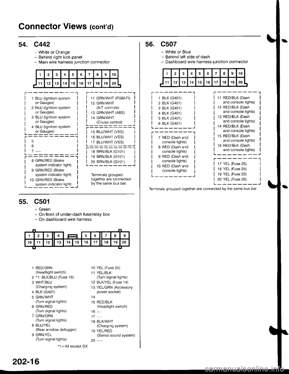
54. c442
- White or Orange- Behind right kick panel- l\,lain wire harness junction connector
r---------Tr---------"1
1 BLU (lgnition systemor Gauges)
2 BLU (lgnition syslemor Gauges)
3 BLU (lgnition systemor Gauges)
4 BLU (lgnition system
L_ or causes)L_-:-:::'-'�____Jt-----------1
11 GRN/WHT (PGM-FD
12 GRN/WHT(A/T controls)
13 GRNMHT (ABS)
14 GRNMHT
L_ lc,r'." .oIr"D_ _ _.jr----------_l
5
6
7L---------JT----------l8 GRN/RED (Brake
system indicator light)
9 GRN/RED (Brake
system indicator light)
10 GRN/RED (Brake
_ system indicator ligh0 -..1
| 15 BLUMHT (vSS) |I 16 BLUMHT (VSS) I
L T?_BLUSTrySS)--..]
l--------- - -l
| 18 BFN/BLK (G101) I| 19 BBN/BLK (G101) || 20 BRN/BLK (c101) |L---------J
Terminals groupedtogether are connectedby the same bus bar.
55. C501
- Green- On tront of under-dash tuse/relay box- On dashboard wire harness
l RED/GFN(Headlight switch)
2 *1 : BLKBLU (Fuse 16)
3 WHT/BLU(Charging systern)
4 BLK (G401)
5 GRNMHT(Turn signal lights)
6 GRN/RED(Turn signal lights)
7 GRN/ORN(Turn signal lights)
8 8LU/YEL(Rear w ndow delogger)
9 GFN/YEL(Turn signal lights)
'10 YEL (Fuse 25)
11 YEL/BLK(Turn signal lights)
12 BLKTYEL (Fuse 14)
13 YEUGRN (Accessorypower socket)
15 RED/BLK(Headlight switch)
1B BLK/WHT(Charglng system)
19 YEL/RED(Stereo sound system)
20
202-16
-1 =All e),cept GX
s6. c507
- White or Blue- Behind left side oJ dash- Dashboard wire harness junction connector
r --------'lT---------l
7 BED (Dash andconsole lights)
B BED (Dash andconsole lights)
I RED (Dash andconsole lights)
10 RFD (Dash andconsole lights)
11 RED/BLK (Dash
and console lights)
12 RED/8LK (Dash
and console lights)
13 RED/BLK {Dashand console lights)
14 RED/BLK (Dash
and console lights)
15 RED/BLK (Dash
and console lights)
16 RED/BLK (Dash
and console lights)L--------J
T--------T
L---_---_J
1 BLK (G401)
2 BLK (G401)
3 8LK {G401)4 8LK (G401)
5 BLK (G401)
6 8LK (G401)L________J
T--------"1
17 YEL (Fuse 25)
18 YEL (Fuse 25)
19 YEL (Fuse 25)
20 YEL (Fuse 25)L--------J
Term nals grouped together are connected by the same bus bat
Page 2127 of 2189
Connector Views (cont'd)
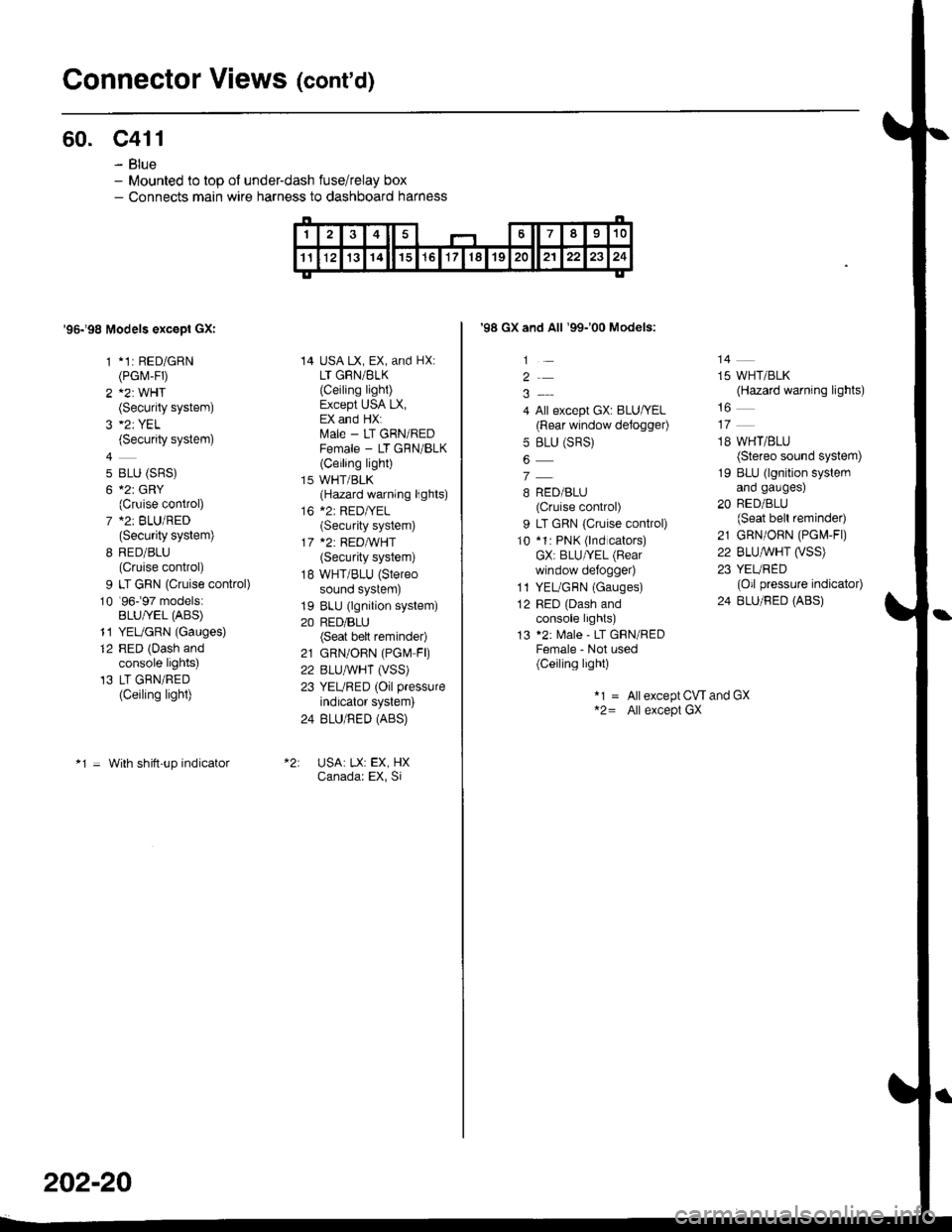
60. c411
- Blue- Mounted to top ol under-dash fuse/relay box- Connects main wire harness to dashboard harness
'95198 Models excepl GXI
1 *1: RED/GRN(PGrvr-FD
2 A2: WHT(Security system)
(Security system)
4
5 BLU (SRS)
6 *2r GRY(Cruise control)
7 *2: BLU/RED(Security system)
8 RED/BLU(Cruise control)
9 LT GRN (Cruise control)
10 '96-�97 models:BLU/YEL (ABS)
11 YEUGRN (Gauges)
12 RED (Dash andconsole lights)'13 LT GRN/RED(Ceiling light)
*1 = With shitt-up indicator
14 USA LX, EX, and HX:LT GRN/BLK
{Ceiling light)Except USA LX,EX and HX:ftrale - LT GRN/REDFemale - LT GRN/BLK(Ceiling light)
15 WHT/BLK(Hazard warning lights)
16 *2: RED|YEL(Security system)
17 *2: REDA/VHT(Security system)
18 WHT/BLU (Stereo
sound system)
19 BLU (lgnition system)
20 RED/BLU(Seat bett reminder)
21 GRN/OBN (PGN4 FD
22 BLUAVHT (VSS)
23 YEURED (Oil pressure
indicator system)
24 BLU/RED (ABS)
USA: LX: EX, HXCanadar EX, Si
202-20
'98 GX and All '99-'00 Models:
1
2
4 All except GX: BLU/YEL(Rear window defogger)
5 BLU (SRS)
7
B RED/BLU(Cruise control)
9 LT GRN {Cruise control)
10 *1: PNK (lnd cators)GX: BLU/YEL (Bear
window defo9ger)
1l YEL/GBN (Gauges)
12 RED (Dash andconsole lights)
13 *2: Male - LT GRN/REDFemale - Not used(Ceiling light)
14
15 WHT/BLK(Hazard warning lights)
18 WHT/BLU(Stereo sound system)
19 BLU (lgnition systemano gaugesl
20 RED/BLU(Seat bell reminder)
21 GRN/ORN (PG[,4-Fl)
22 BLU,ryVHT O/SS)23 YEURED(Oil pressure indicator)
24 BLU/RED (ABS)
*1 = Allexcept CW and GX*2= All except GX
Page 2129 of 2189
Connector Views (cont'd)
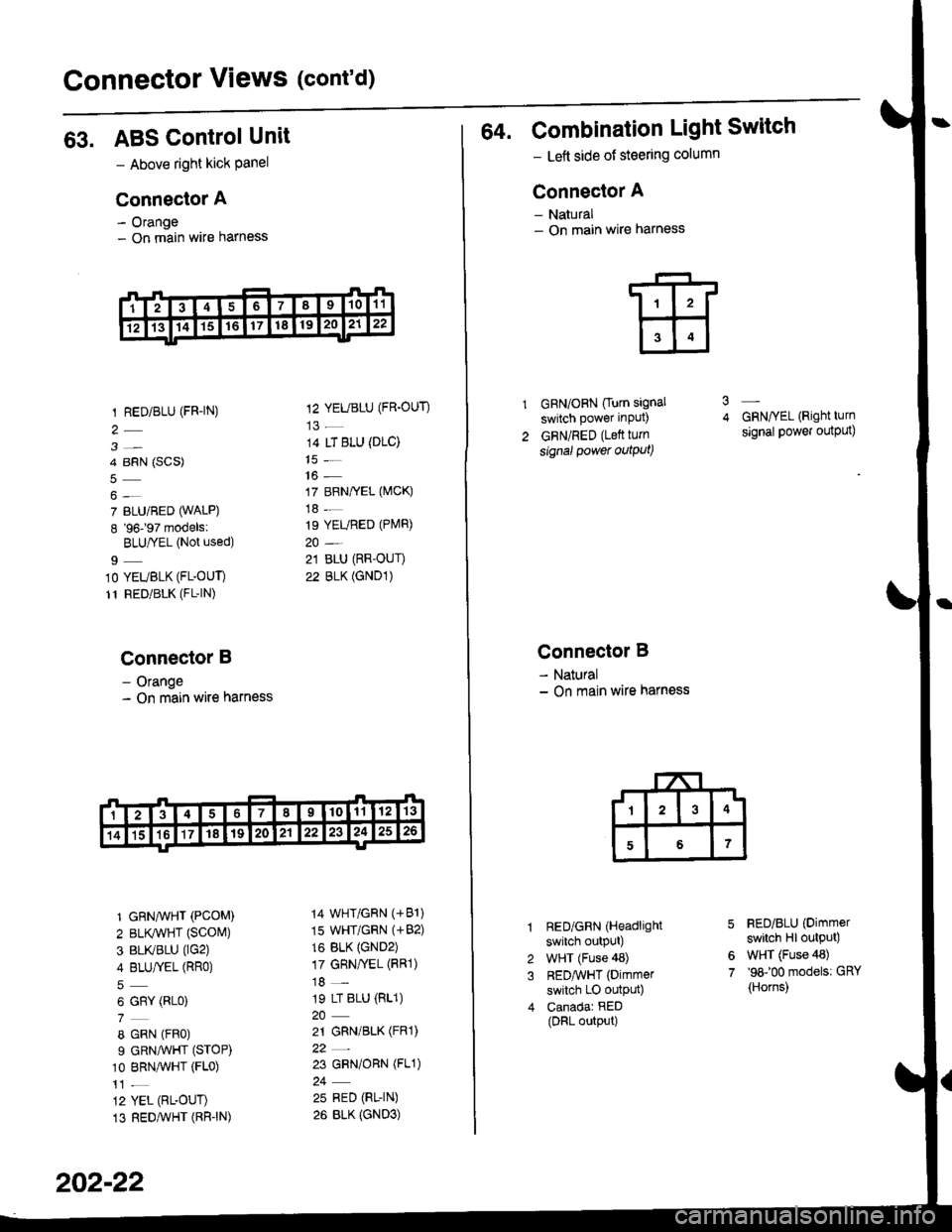
63. ABS ControlUnit
- Above right kick Panel
Connector A
- Orange- On main wire harness
1 RED/BLU (FR-|N)
3-
4 BRN (SCS)
7 BLU/BED (WALP)
8 '96197 models:
BLU|YEL (Not used)
9_
10 YEUBLK (FL-OUT)
11 RED/BLK (FL-|N)
Connector B
- Orange- On main wire harness
1 GRN^VHT (PCOM)
2 BLr(wHT {SCOM)
3 BLIVBLU (lG2)
4 BLU/fEL (RRo)
6 GRY (RLo)
8 GRN (FRo)
9 GRNAVHT (STOP)
10 BRNAVHT (FLo)
12 YEL (RL-OUT)
13 REDAVHT (RR"IN)
12 YEUBLU (FR.OUT)
14 LT BLU (DLC)
16 -
17 BRN/YEL (MCK)
18 -
19 YEURED (PlVlR)
21 BLU (RR-OUI)
22 BLK (GND1)
14 WHT/GRN (+81)
15 WHT/GRN (+82)
16 BLK {GND2)17 GRN/yEL (FRl)
18 -
19 LT BLU (RL1)
21 GRN/BLK (FRl)
22_
23 GRN/ORN (FL1)
25 RED (RL-IN)
26 BLK {GND3)
202-22
64. Combination Light Switch
- Lett side of steering column
Connector A
- Natural- On main wire harness
GRN/ORN Ourn signal
switch power input)
GRN/RED (Lett turn
signal power outqut)
3
Connector B
- Natural- On main wire harness
RED/GRN (Headlight
switch outpUt)
WHT (Fuse 48)
REDAvHT (Dimmer
switch LO outpu0
Canadar RED(DRL output)
GRN/YEL (Right turn
signal power output)
FED/BLU (Dimmer
switch Hl output)
WHT (Fuse 48)'98100 models: GRY
{Horns)
6
7
Page 2137 of 2189
Connector Views (conrd)
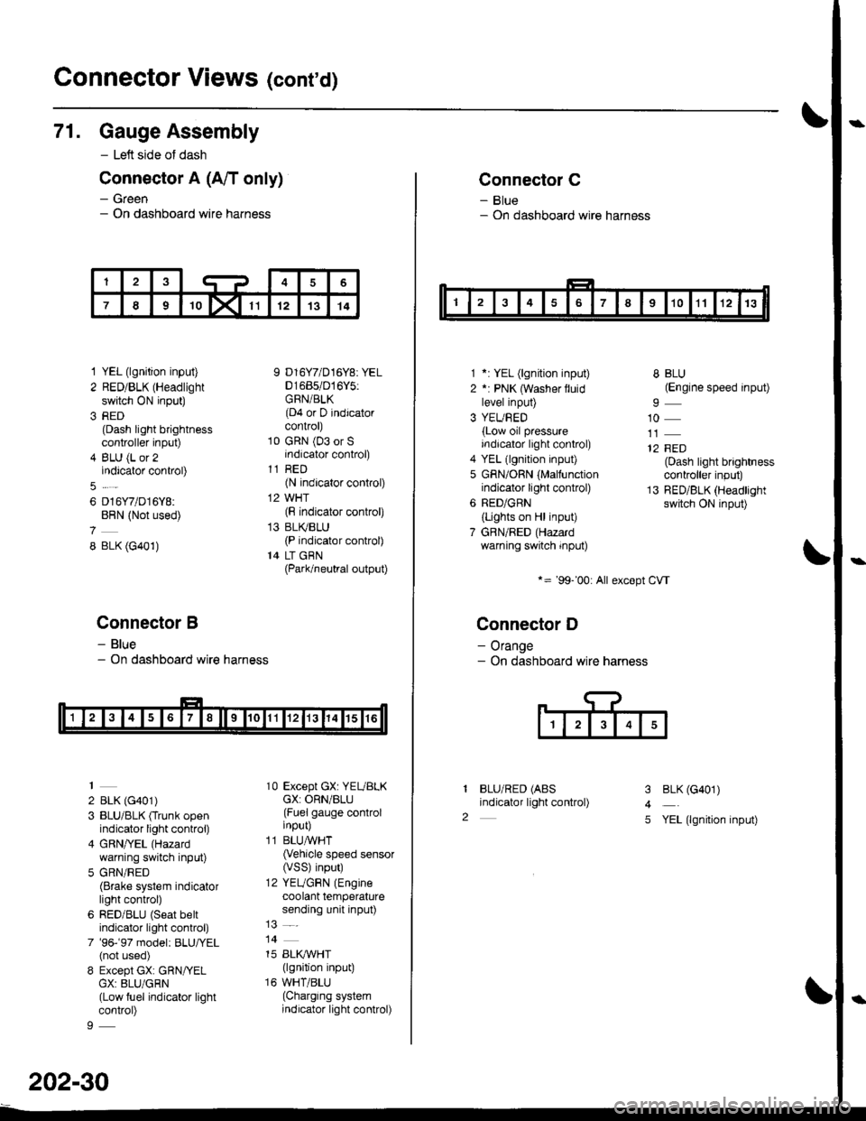
71. Gauge Assembly
- Left side of dash
Connector A (A/T only)
- Green- On dashboard wire harness
1 YEL (lgnition input)
2 RED/BLK (Headlight
switch ON input)
3 RED(Dash light brightnesscontroller input)
4 BLU (L or 2indicator control)
6 D16Y7/D16Y8:BRN (Not used)
8 BLK (G401)
Connector B
- Blue- On dashboard wire harness
2 BLK (G401)
3 BLU/BLK (Trunk openindicator light control)
4 GRN/YEL (Hazard
warning switch input)
5 GRN/RED(Brake system indicatorlight control)
6 RED/BLU (Seat beltindicator light control)
7 '96-'97 model: BLU,ryEL(not used)
8 Except GX: GRN/YELGX: 8LU/GRN(Low fuel indicator lightcontrol)
9 D16Y7/D16Y8: YEL01685/016Y5:GRN/BLK(D4 or D indicatorcontrol)
10 GRN (03 or Sindicator control)
11 RED(N indicator control)
12 WHT(F indicator control)
13 BLI(BLU(P indicator control)
14 LT GBN(Park/neutral output)
10 Except GX: YEUBLKcX: ORN/BLU(Fuel gauge controlinput)
11 BLUAVHT(Vehicle speed sensor(VSS) input)
12 YEUGRN (Engine
coolant temperaturesending unit input)
14
15 BLI(IVHT(lgnition input)
16 WHT/BLU(Charging systemindicator light control)
202-30
Connector C
- Blue- On dashboard wire harness
1 *: YEL (lgnition input)
2 *: PNK (Washer lluidlevel input)
3 YEUBED(Low oil pressureindicator light control)
4 YEL (lgnition input)
5 GRN/ORN (Malfunctionindicator light control)
6 RED/GRN
{Lights on Hl input)
7 GBN/RED (Hazardwarning switch input)
*= '99-'00: All except CVT
Connector D
- Orange- On dashboard wire harness
BLU/RED (ABS
indicator light control)
8 BLU(Engine speed input)
10
12 FED(Dash light brightnesscontroller input)
13 RED/BLK (Headlightswitch ON input)
I
2
3
4
5
BLK (G401)
YEL (lgnition input)