Page 1923 of 2189

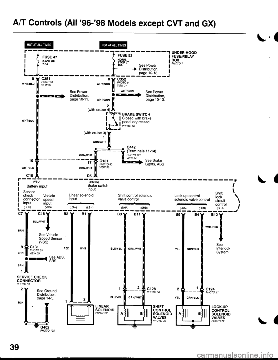
A/T Controls (All '96-'98 Models except CW and GX)
r.(
r5A see power I
--li$"i':,--iL-.At----- __*____..,,53-j"i__8 Y 93^s_1- 8Y C352'"'".u
I iii'i"' ""'o"* | i#?1o.'
ll see power ll wrr cnn See Power
la--- oisirioution, ! -t 6iri,iortion,
[--*
t"*tr*t1,'.':,:;i. wHr GFN lt page 10-13.
,i(with crurse 4) Al"'rl(-1 BRAKE swrrcH
| lClosed.with brake
Ir-I Il,?,|fll,"P'"""oL*--J
c18lr 82
"ar-"t I
I
See VehicleSpeed Sensor(vss)
ct31PHO|O 35vtEw 59
r< See ABs'
UNDER"HOODFUSE/RELAYBOXI
I
I
BFN
9
BFN
o
""il
SERVICE CHECKCONNECTOR
See GroundDistribution,page 14-5.
I
YEL
c124
L__lH:""".: G402
SHIFTCONTROLSOLENOIDVALVES
LOCK-UPCONTROLSOLENOIDVALVES
,. L ---- - - --.#ku" :::::'o f
---------tty"c;11,, l;-,f l;?t?:if,-:;tr *";.!, *"
c10 ,| Ds^'
I Lvou, (SKSV,
! Battery input Brake lwitch I
service nPUt ehin t;;;;i- Vehrcte Linear sotenoid Shift controt sol€noid Lock-up conkol iJ'[
'\
connector speed input valve conhol solenoid vatve controt tliiJ"it \uo trut tconrrol t: (scs) (vss) {Ls}) rLs ) {sHA' {SHB, (LCA) (LCB) {S-U) .--:-'--J
ct28
39
GFN/ALK
(
Page 1929 of 2189
A/T Gontrols ('96-'98 CVT) (conrd)
sfr
Dl0
YEUALU
@
I J
-'u-.'-.i - - -
I 3X3'5"
L]Sffiflulilir:
lLlftT:l,', "*,
3=:. fierminalslT-20)
*l
v56
r+
r andLights
"," I
;I
-JI!.
br
iee Dash
vtEw 56
IISs€ PowerDisfibution,page 10.6.Se€ PGIV-FI,page 23-12.See Dash arConsole Ligl
I FEo/ELK
lazIMANIFOLDABSOLUTEPRESSURE(MAP}
il'-
4o
(
REO/ELK-{ i["r.r,
RED/BLK
cl't5fferminals8n4)
wEw 3a
#.1 !3"" r,
c'l31PHOfO 85vtEw 59
1lc410
vtEw 35
Se€ GroundDistribution,page 1+7.
ORN/BLK
Dl1D12
a
-----1 ENGINE
I l-c_qllFgL
I l8l,:'�,T* lffiff" iF!&i:'
L_"S.f___ __y,' _j,ii!,J?"*
a
i
--r3 - -.
:F.
- - -.-o ,'i6i I rRANsMrssroN
I TP MAP
i iln'o, ;;;' iiaicato, i[f[!!! ftcM)
I input input conkol IVie-Jo:e'-L - - -- - - - - - - - - - - J
39-6
ir=l*--:*"ii*lF.?}t?''------JvtEwTa
\
Page 1942 of 2189
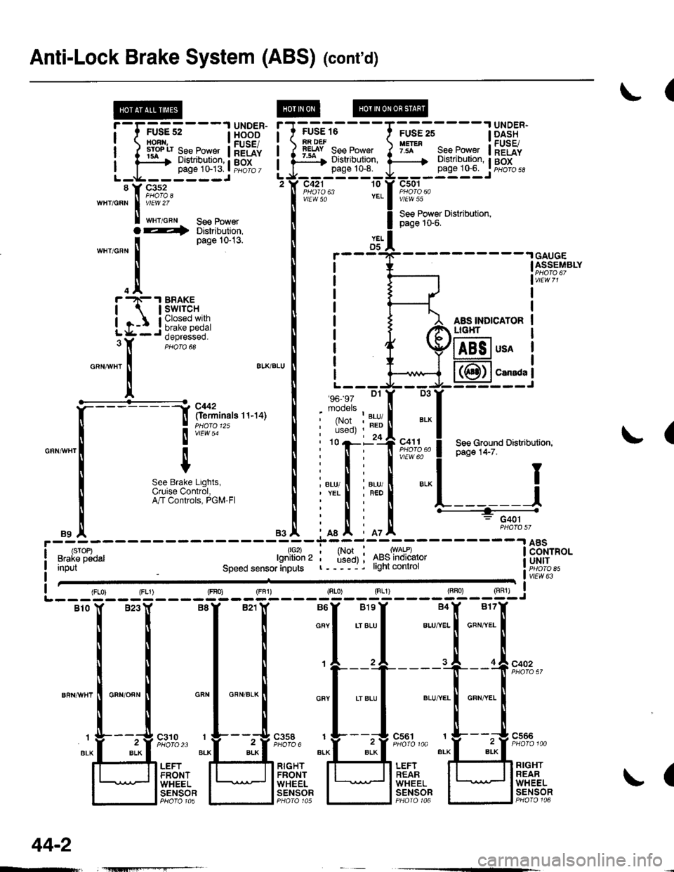
Anti-Lock Brake System (ABS)
UNDER.HOOD
H'.'"" ii[*:'*"
1
GFN
c357PHOTO 4
c359PHO|O 610
BEO
Grqlnd 2{GX!2)
l"l Fi* :l :l
!Ji I-J
.-L-----
i il
TPHOIO 125
44
Page 1943 of 2189
UNDER-HOODABS FUSE/RELAY BOX
r------1
c356
FUSE 63MTNCHECK7.54
c357 2
FUSE 61PUIiPolon
c356
ABSPUMPMOTOR
i-.t_____l
*fitr
3
YEURED
A19
(PMR) (MCK) IPump Motor Icomm6n motdr check IRight rear ABS LeftftontABS ;i; !
solenoid control solenoid controt loni of !
\^li Service.check DLC I
/ connector input inpuvoltput i&------ ---_____J
11.I A14 r aBs coNrRor_lrNrBRN I rr eru I LT BLU vttt 63trrt sRS. ATcontrols t-! vccvnv 1"Tl 'Tl ':c360
SERVICE DATA LINKCHECK CONNECTORCONNECTOR (DLC)PHoIo 83 See GrOUnd pHOrO so
Pll'lo.,jpn. p y:l:!:1
*L_T'=Llj:t
See Ground
'--=-Ea; *---==4oi
RightRearABSSolenold(Out)
nightReerABSSoloroid(ln)
LettFrontABSSolenoid(od)
PHA|A 125 PHOfO,/
44-1
Page 1944 of 2189

Anti-Lock Brake System (ABS) (cont'd)
(
FUSE 16iA DEFlEtsY See Power:ar Distribution,page 10-8.
c421 10
vlEW 50
'96- 97 Dl
mooels
.I UNDER-
page 1G6. I pHoro 5d
c501
vlEW 55
See Power Distribution,page 1S6.
AAS INDICATORLIG}IT
!'-r;us?;---l H5BE"
ilrryilrfi#ftilHriL-g------JL-g------J'tr F,1%'wHr/GRN I v/El.V 2Z
I t"r,o"" se€ Power
YELD5GAUGEASSEMBLY
usA
CarsdaI
(
D3
', ',i:,tr?""" ! P"g" t+-z".r',
*
! see cround Distributiofl,
".., I i"., I ".-l I;nl
iffit L------J
' n : G401
mI iot
T1*l ^*ry*l:-------l 8Bi"o.' used) ; 4ts5lnolcalor i UH|Tr----j. light conlrol r. iicib ett,"LTfflo",Input
1lo2)lgnition 2
Speed sensor anputsvlEw 63
(
{FLo) {FL1) (FBo) {FF1) (Rr"o) Sg____gT]-__g,l-j
Blo lf B23Y B8Y B21lf B6Y BlsY B4X B17f
i i I i o""l .,",-ul u.,"..1 o"",'.. I
rrttl
| | | I ,l ,l .I of"on"
ll ll I ti
't---'+----"[ --f !'?'%,'
""n*",lo"no""l *"1 *"*-l *"1 .'"."1 *,*.[ "**.I
I r L___t"" " t__t"." 1___!".""
"r.f_ "4::3' ;FJ,;::; ":f3:::1'' "lf-*i":''
t' ,.,Jtri"?r. ll;l]flffi lFli.ft. lU]flqtfl
l l"#tgl I lt5T8?l I lt"F"Ti?l I lt;Tt?f
O--t Distribution,
'n"r,o^n
I
Page 10-13'
.trr -N- .I BRAKE
| | swrrcH
igr:*
o"ntr"r
!
a'KBLU
It
""*[:-l
ftff^"n"o''''ot
I
", I
m;r""#,usi:",
".1
44-2
Page 1945 of 2189

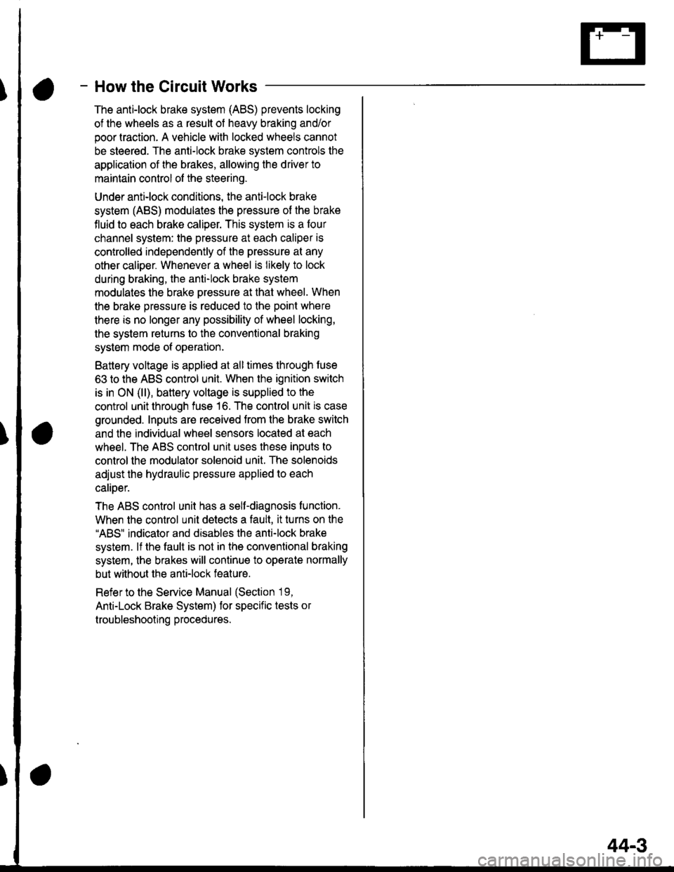
- How the Circuit Works
The anti-lock brake system (ABS) prevents locking
of the wheels as a result of heavy braking and/or
poor lraction. A vehicle with locked wheels cannot
be steered. The anti-lock brake system controls the
application of the brakes, allowing the driver to
maintain control of the steering.
Under anti-lock conditions, the antilock brake
system (ABS) modulates the pressure of the brake
tluid to each brake caliper. This system is a four
channel system: the pressure at each caliper is
controlled independently of the pressure al any
other caliper. Whenever a wheel is likely to lock
dunng braking, the anti-lock brake system
modulates the brake oressure at that wheel. When
the brake pressure is reduced to the point where
there is no longer any possibility of wheel locking,
the system returns to the conventional braking
system mode of operation.
Battery voltage is applied at all times through fuse
63 to the ABS control unit. When the ignition switch
is in ON (ll), battery voltage is supplied to the
control unit through fuse 16. The control unit is case
grounded. Inputs are received from the brake switch
and the individual wheel sensors located at each
wheel. The ABS control unit uses these inputs to
control the modulator solenoid unit. The solenoids
adjust the hydraulic pressure applied to each
calioer.
The ABS control unit has a self-diagnosis function.
When the control unit detects a fault, it turns on the"ABS" indicator and disables the anti-lock brake
system. lf the fault is not in the conventional braking
system, the brakes will continue to operate normally
but without the anti-lock feature.
Refer to the Service Manual (Section '19,
Anti-Lock Brake System) for specific tests or
troubleshooting procedures.
44-3
Page 1975 of 2189
I
I
I
I
I
&3?linars rz.zor i33o,.no
3in""li"?''""
,
"i*l?""
"*o""tr ""**"tr' """"*l'
ttl
".[ ",1 ,.[
-;--1------T-----T'"
lEil$fi' I I I
irffiPl | | I
'ip^"rf'ffi"'?H""9
J[i@)-l r- k- |
I canada | \-l see Gauges
1t;1
#ra-tu1-*
N|GHTTURI'lslclrlAlINOICATORLIGIIT
H
snsIXDICATORLIG}IT
1I
----J
GAUGEASSEMBLYPHOIO 67vlEw 71=[ =
See ABS
*l =
See sRs
c507(Termlnals 1.6)
vlEw 56
BLU/NED
S€
==:
Groufte 14-7.Distribtltion,Ground,14-7.S€e (page
(cont'd)
80-1
I
!l
i lsr
\e
\\\
\
I
I
t
I
I
l____l
- G4o1PHOIO 57
Page 2030 of 2189

Power Door Locks (cont'd)
Keyless Entry Does Not Work In Any
Mode
NOTE: Before beginning, verify that all the
transmitters are programmed to the vehicle.
1 . Does the radio work properly?
Yes - Go to step 9.
No - Go to the neld step.
NOTE: For steos 2 - 8. refer to the schematic dia-
gram for the Stereo Sound System on page 150.
2. Are fuses 28 (in the under-dash fuse box) and
fuse 47 (in the under-hood fuse box) OK?
Yes - Go to step 4.
No - Replace the blown fuse, then go to the
nen steo.
3. Does the fuse blow again?
Yes - Locate and repair the short.
No- Retest the system.
4. ls the vehicle equipped with the optional security
system?
Yes - Go to the next steP.
No - Go to steD 6.
5. Does the keyless entry work correctly when the
security control unit connector is disconnected?
Yes - Faulty security system, go to security
system for f urther troubleshooting.
No - Go to the next step.
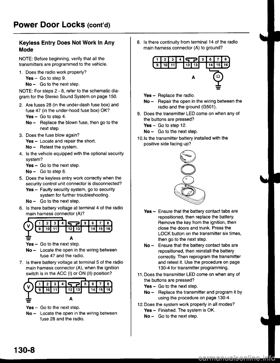
6. ls there battery voltage at terminal 4 of the radio
main harness connector (A)?
7.
=A
Yes - Go to the nen step.
No - Locate the open in the wiring between
tuse 47 and the radio.
ls there battery voltage at terminal 5 of the radio
main harness connector (A), when the ignition
switch is in the ACC (l) or ON (ll) position?
Yes - Go to the next step.
No - Locate the open in the wiring between
fuse 28 and the radio.
130-8
8. ls there continuity from terminal 14 of the radio
main harness connector (A) to ground?
Yes - Replace the radio.
No - Repair the open in the wiring between the
radio and the ground (G501).
9. Does the transmitter LED come on when any ot
the buttons are oressed?
Yes - Go to steo 12.
No - Go to the next steo.'10.ls the transmitter battery installed with the
positive side facing up?
Yes - Ensure that the battery contact tabs are
repositioned, then replace the battery.
Remove the key from the ignition, then
close the doors and trunk. Press the
LOCK button on the transmitter six times,
then go to the next step.
No - Ensure that the baftery contact tabs are
repositioned, then reinstall the batlery
correctly. Then reprogram the transmitter
and retest it. Use the procedure on page
1 30-4 f or transmitter programming.
11 . Does the transmitter LED come on when any of
the buttons are oressed?
Yes - Go to the next step.
No - Replace the transmitter and program it by
using the procedure on page 130-4.
12.Does the system work properly in all modes?
Yes - Finished. The system is OK.
No - Go to the next steD.