Page 834 of 2189
Clutch
lllustrated Index (A4RA, B4RA Transmission)
3RD CLUTCH
O-RINGSBeplace. CLUTCH ptSTON
lST CLUTCH
CLUTCHDRUM
CLUTCH ENDPLATE
SPRING RETAINER
RETUNN SPRING
CLUTCH DRUM
SNAP RING
CLUTCH END
CLUTCH PLATESStandard thickness:1.6 mm (0.063 in)
SNAP RING
CHECK VALV€
\
14-156
Page 836 of 2189
Clutch
lllustrated Index (M4RA Transmission)
3RD CLUTCHCLUTCHDRUM
CLUTCH PISTON
DISC SPRING
CLUTCII END
rST CLUTCH
CLUTCH E D
SI{AP RIiIG
CLUTCH PLATESStandard thickness:1.6 mm (0.063 in)
CHECK VALVE
L
14-158
Page 843 of 2189

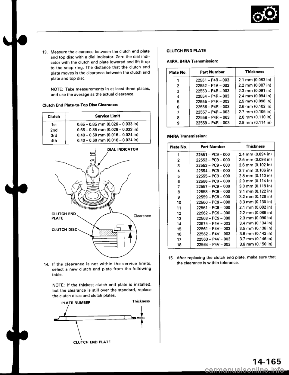
13. Measure the clearance between the clutch end plate
and top disc with a dial indicator' Zero the dial indi-
cator with the clutch end plate lowered and lift it up
to the snap ring. The distance that the clutch end
plate moves is the clearance between the clutch end
plate and top disc.
NOTE| Take measurements in at least three places,
and use the average as the actual clearance.
Clutch End Plste-to-Top Disc Clearance:
OIAL INDICATOR
CLUTCH ENDPLATEClearance
14.
CLUTCH DISC
lf the clearance is not within the service limits,
select a new clutch end plate from the following
table.
NOTE: lf the thickest clutch end plate is installed,
but the clearance is still over the standard, replace
the clutch discs and clutch plates.
PLATE NUMBERThickn6ss
ClutchSerYice Limit
1st
2nd
3rd
4th
0.65 - 0.85 mm (0.026 - 0.033 in)
0.65 - 0.85 mm (0.026 - 0.033 in)
0.40 - 0.60 mm (0.016 - 0.024 in)
0.40 - 0.60 mm (0.016 - 0.024 in)
CLUTCH ENO PLATE
14-165
Plate No.Part NumberThickness
,l
2
J
4
5
6
1
8q
22551 - P4R - 003
22552-P4R-003
22553-P4R-003
22554-P4R-003
22555-P4R-003
22556-P4R-003
22557 -P4B-OO3
22558-P4R-003
22559-P4R-003
2.1 mm (0.083 in)
2.2 mm (0.087 in)
2.3 mm (0.091 in)
2.4 mm (0.094 in)
2.5 mm (0.098 in)
2.6 mm (0.102 in)
2.7 mm {0.106 in)
2.8 mm {0.110 in)
2,9 mm (0.1 '14 in)
CLUTCH END PLATE
A4RA, g4RA Transmission:
M,IRA Transmi$ion:
15. After replacing the clutch end plate. make sure that
the clearance is within tolerance.
Plate No.Part NumberThickness
1
3
'l
.'q
10
11't2
13
14
15'16
17
18
22551 - PCg - 000
22552-PCg-000
22553-PCg-000
22554-PCg-000
22555-PCg-000
22555-PCg-000
22557-PCg-000
22558-PCg-000
22559-PCg-000
22560-PCg-000
22561 - PCg - 000
22562-PCg-000
22563-PCg-000
22574 - P4V - 003
22561 - P4V - 003
22562- P4V - 003
22563-P4V-003
22564-P4V-003
2.4 mm (0.094 in)
2.5 mm (0.098 in)
2.6 mm {0.102 in)
2.7 mm (0.106 in)
2.8 mm (0.110 in)
2.9 mm (0.114 in)
3.0 mm {0.118 in)
3.1 mm (0.122 in)
3.2 mm (0.126 in)
3.3 mm (0.130 in)
2.1 mm (0.082 in)
2.2 mm {0.086 in)
2.3 mm (0.090 in)
3.4 mm (0.134 in)
3.5 mm (0.138 in)
3.6 mm (0.142 in)
3.7 mm (0.146 in)
3.8 mm (0.150 in)
Page 847 of 2189
OilSealRemoval
1. Remov€ the differential assembly.
2, Remove the oil seal from the transmission housing,
OIL SEALRoplace.
the oil seal from ths torque converterRemove
housing.
OIL SEALReplace.
TOROUE CONVERTEFHOUSING
Oil Seal Installation/Side Glearance
1. Install a 2.50 mm (0.098 in) set ring,80 mm in trans-
mission housing.
NOTE: Do not install the oil seal vet.
RING, 80 mm
TRAITISMISSlONHOUS|l{G
Install the differential assembly into the torque con-
verter housing using the specialtool as shown.
Install the transmission housing and tighten the
bolts {see page 14-178 and 14-179).
{cont'd)
14-169
Page 848 of 2189

Differential
Oil Seal Installation/Side Clearance (cont'd)
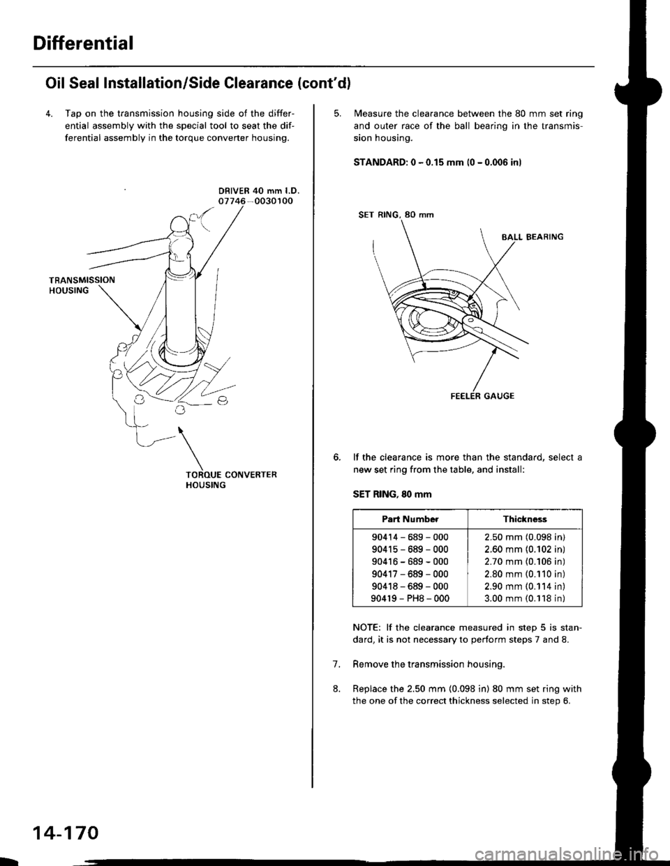
4. Tap on the transmission housing side of the differ-
ential assembly with the special tool to seat the dif-
ferential assembly in the torque converter housing.
DRIVER 40 mm l.D.
L
14-170
5. N4easure the clearance between the 80 mm set ring
and outer race of the ball bearino in the transmis-
sion housing.
STANDARD: 0 - 0.15 mm (0 - 0.006 inl
SET RING, 80 mm
BALL BEARING
lf the clearance is more than the standard, select a
new set ring from the table, and install:
SET RING, 80 mm
NOTE: lf the clearance measured in step 5 is stan-
dard, it is not necessary to perform steps 7 and 8.
Remove the transmission housing.
Replace the 2.50 mm (0.098 in) 80 mm set ring with
the one of the correct thickness selected in step 6.
7.
Part NumberThickness
90414-689-000
904r5-689-000
90416-689-000
90417-689-000
90418-689-000
904r9-PH8-000
2.50 mm (0.098 in)
2.60 mm {0.102 in)
2.70 mm {0.106 in)
2.80 mm (0.110 in)
2.90 mm (0.114 in)
3.00 mm (0.118 in)
Page 849 of 2189
9. lnstall the new oil seal flush with the transmission
housjng using the special tools as shown
DRIVER077i(} - 0010000
PILOT.26x30mm07JAO - PH80200
DRIVER ATTACHMENT, 68 mm
079i17-6110501
10. lnstall the new oil seal flush with the torque con-
verter housing using the specialtools as shown
DRIVER07749 - 0010000
14-171
Page 852 of 2189

Transmission Housing Bearings
L
Mainshaft/Countershaft Bearings Replacement
To remove the mainshaft and countershaft bearings
from the transmission housing, expand each snap
ring with snap ring pliers, then push the bearing out
using the special tools and a press as shown.
NOTE: Do not remove the snap rings unless it's
necessary to clean the grooves in the housing.
DRIVER07749 - 0010000
ATTACHMENT,62x68mm
PRESS
\
07746 -
DFIVEB07749 - 0010000
TTACHMENT
ATTACHMENT
. Mainshaft Bearing Installation us€:
ATTACHMENT. 72 x 75 mm
07746 - 0010600. Countershaft Bearing Installation use:
ATTACHMENT, 62 x 68 mm
077/16 - 0010500
IRN{L{r.)n
\bZ
MAINSHAFT BEARING
L
14-174
SNAP RING
Expand each snap ring with snap ring pliers, insert
the new bearing part-way into the housing using
the special tools and a press as shown, Install thebearing with the groove facing outside the housing.
NOTE: Coat all parts with ATF.
Release the pliers, then push the bearing down intothe housing until the ring snaps in place around it.
07749 - 0010000
ATTACHMENT
. Mainshaft Bearing Removal use:
ATTACHMENT, 72 x 75 mm
077/16 - 0010600. Counte6haft Bsaring Removal use:
ATTACHMENT, 62 x 68 mm
07746 - 0010500
After installing the bearing verify the following:
. The snap ring is seated in the bearing and hous-
ing grooves.
. The ring end gap is correct.
(0 - 0.28 in)ENDGAP:0-7mm
Page 853 of 2189
Reverse ldler GearPark Stop
lnstallation
1, lnstall the reverse idler gear.
Install the reverse idler gear shaft holder and needle
bearing into the transmission housing, then tighten
the bolts.
6 x 1.0 mm12 N.m ll .2 kgf'm,
8.7 tbf.ftl
GEAR
'1.
Inspection/Adiustment
Set the park lever in the E position.
Measure the distance between the park pawl shaft
and the park lever roller pin as ahown.
STANDARD: 72.9 - 73.9 mm 12.87 - 2.91 inl
PARK PAWLSHAFT
lf the measurement is out of tolerance, select and
install the appropriate park stop from the table
Delow.
PARK STOP
PARK STOP
After replacing the park stop, make sure the dis-
tance is within tolerance.
/A\Measuring\v
MarkPart Numb€rLr12
I24537-PAg-00311.00 mm
(0.433 in)
11.00 mm
(0.433 in)
24538-PAg-00310.80 mm(0.425 in)
10.65 mm
(0.419 in)
24539-PAg-00310.60 mm(0.417 in)
10.30 mm(0.406 in)
14-175