Page 1496 of 2189
Connector ldentification and WireHarness Routing
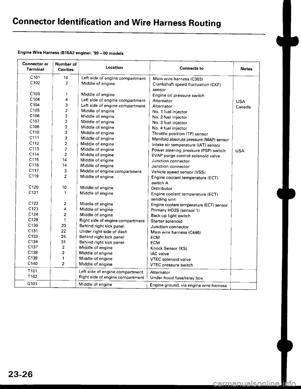
Engine Wire Harness {81642 engine}: .99 - 00 models
c 101
c102
cl03
c104
c 104
c'105
c106
cl01
c108
c110
cl11
cl12
c1'13
c114
c115
c117
cl19
c120
c121
c122
c123
c124
c129
c130
c l31
c133
c134
c137
c 138
c139
c140
Left side of engine companment
Middle of engine
Middle of engine
Left side of engine compartment
Left side of engine compartmentlvliddle of engine
Middle ot engine
Middle of engine
Middle of engine
Middle of engine
Middle of engine
Middle ot engine
Middle of engine
Middle of engine
Middle of engine
Middle of engine
Middle of engine compartment
Middle of engine
Middle of engine
Middle of engine
lMiddle of engine
Middle of engine
Middle of engine
Right side of engine compartment
Behind right kick panel
Under right side of dash
Behind right kick panel
Behind right kick panel
Middle of engine
Middle ot engine
lMiddle of engine
Middle of engine
10
2
,]
4
3
2
2
2
2
3
3
2
2
2
14
14
3
2
'10
'I
2
4
2
1
20
22
25
31
2
2
I
Main wire harness (C303)
Crankshaft speed fluctuation (CKF)
sensor
Engine oil pressure switch
Alternator
Alternator
No. 1 fuel injector
No. 2 tuel injector
No. 3 fuel injector
No. 4 fuel injector
Throttle position (TP) sensor
Manifold absolute pressure (MAP) sensorIntake air temperature (lAT) sensorPower steering pressure (PSP) swjtchEVAP purge control solenoid valve
Junction connector
Junction connector
Vehicle speed sensor (VSS)
Engine coolant temperature (ECT)
switch A
Distributor
Engine coolant temperature (ECT)
sending unit
Engine coolant temperature {ECT) sensorPrimary HO2S (sensor 1)
Back-up light switch
Starter solenoid
Junction connector
Main wire harness (C446)
ECM
ECtvl
Knock Sensor {KS)IAC valve
VTEC solenoid valve
VTEC pressure switch
USA
Canada
Left side of engine companment
Right side of engine compartment
Engine ground, via engine wire harness
Page 1508 of 2189
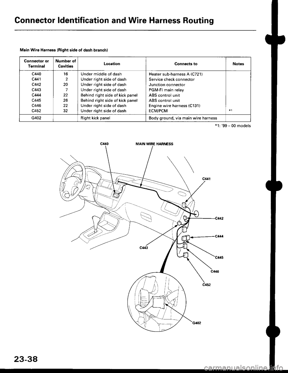
Gonnector ldentification and Wire Harness Routing
Msin Wire Harness (Right side oI dash branch)
Connector or
Terminal
Number of
CavitiesLocationConnects toNotes
c440
c441
c442
c443
c4M
c445
c446
c452
16
2
20
7
22
22
Under middle of dash
Under right side of dash
Under right side of dash
Under right side of dash
Behind right side of kick panel
Behind right side of kick panel
Under right side of dash
Under right side of dash
Heater sub-harness A (C721)
Service check connector
Junction connector
PGM-Fl main relay
ABS control unit
ABS control unit
Engine wire harness (C131)
ECM/PCM
G402Right kick panelBody ground, via main wire harness
*'l: '99 - 00 models
23-38
Page 1533 of 2189
(l'-
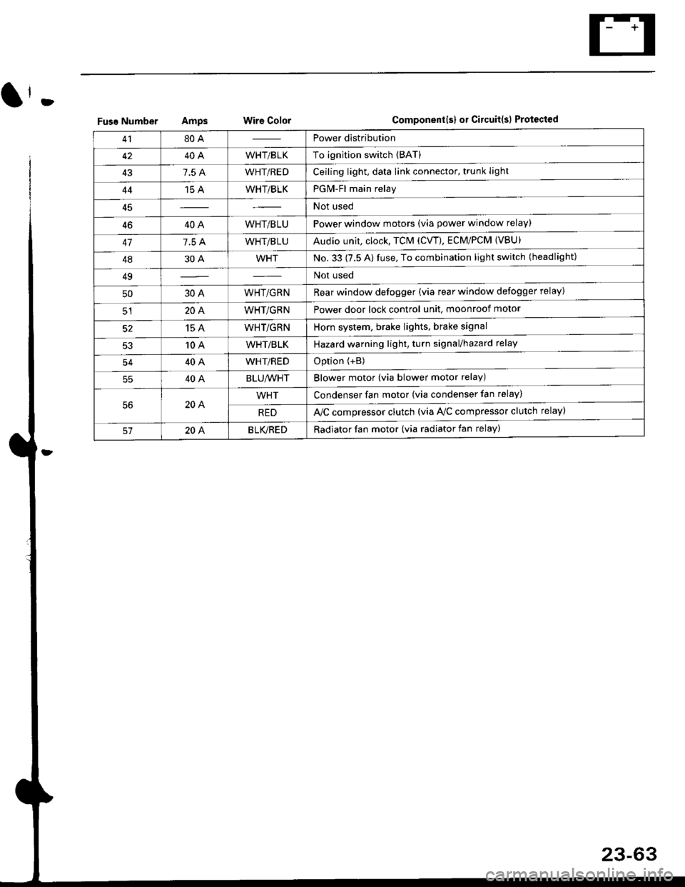
Fuse NumberAmpswire ColorComponent(s) or Circuitlsl Protect€d
4180APower distribution
4240AWHT/BLKTo ignition switch (BAT)
437.5 AWHT/REDCeiling light, data link connector, trunk light
4415 AWHT/BLKPGM-Fl main relay
Not used
4640AWHT/BLUPower window motors (via power window relay)
477.5 AWHT/BLUAudio unit, clock, TCM (CVT), ECM/PCM (VBU)
4830AWHTNo.33 (7.5 A) fuse, To combination light switch (headlight)
49Not used
5030AWHT/GRNRear window defogger (via rear window defogger relay)
cl20AWHT/GRNPower door lock control unit, moonroof motor
15 AWHT/GRNHorn system, brake lights, brake signal
10 AWHT/BLKHazard warning light, turn signal/hazard rclay
54404WHT/REDOption {+B)
5540ABLU,A/VHTBlower motor (via blower motor relay)
204WHTCondenser fan motor (via condenser fan relay)
REDl'lc compressor clutch (via IVC compressor clutch relay)
204BLVBEDRadiator fan motor (via radiator fan relay)
23-6
Page 1565 of 2189
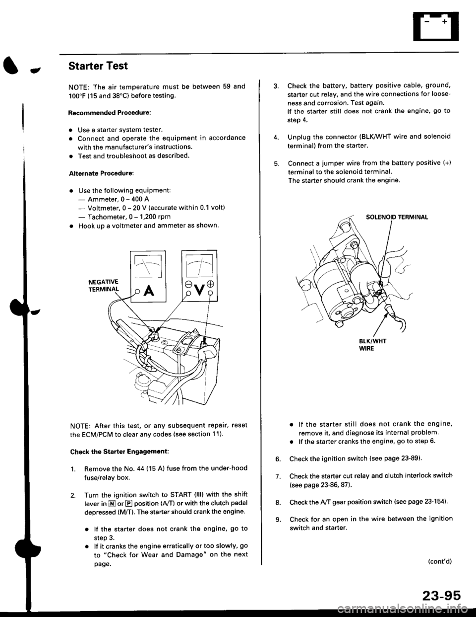
-Starter Test
NOTE; The air temoerature must be between 59 and
100'F (15 and 38"C) before testing.
Recommended Procedure:
. Use a staner system tester.
. Connect and operate the equipment in accordance
with the manufacturer's instructions.
. Test and troubleshoot as described,
Alternate Procedurg:
. Use the following equipment:- Ammeter, 0 - 400 A
- Voltmeter, 0 - 20 V (accurate within 0.1 volt)
- Tachometer, 0 - 1,200 rpm
. Hook up a voltmeter and ammeter as shown.
NEGATIVETERMINAL
NOTE: After this test, or any subsequent repair. reset
the ECM/PCM to clear any codes (see section l1)
Check the Start€r Engagemont:
1. Remove the No. 44 (15 A) fuse from the under-hood
fuse/relay box,
2. Turn the ignition switch to START (llll with the shift
lever in E or E position (rVT) or with the clutch pedal
depressed {M/T). The starter should crank the engine.
. lf the starter does not crank the engine, go to
step 3.
. lf itcranksthe engineerraticallyortooslowly, go
to "Check for Wear and Damage" on the next
page.
Check the battery. battery positive cable, ground,
starter cut relay, and the wire connections for loose-
ness and corrosion, Test again.
lf the starter still does not crank the engine, go to
step 4,
Unplug the connector (BLK,/WHT wire and solenoid
terminal) from the starter,
Connect a jumper wire from the battery positive (+)
terminal to the solenoid terminal.
The starter should crank the engine.
. lf the starter still does not crank the engine,
remove it, and diagnose its internal problem
. lf the startercranksthe engine, goto step 6.
Check the ignition switch (see page 23-891.
Check the starter cut relay and clutch interlock switch
(see page 23-86,87).
Check the A/f gear position switch (see page 23-154).
Check for an open in the wire between the ignition
switch and starter.
7.
(cont'd)
23-95
9.
Page 1579 of 2189
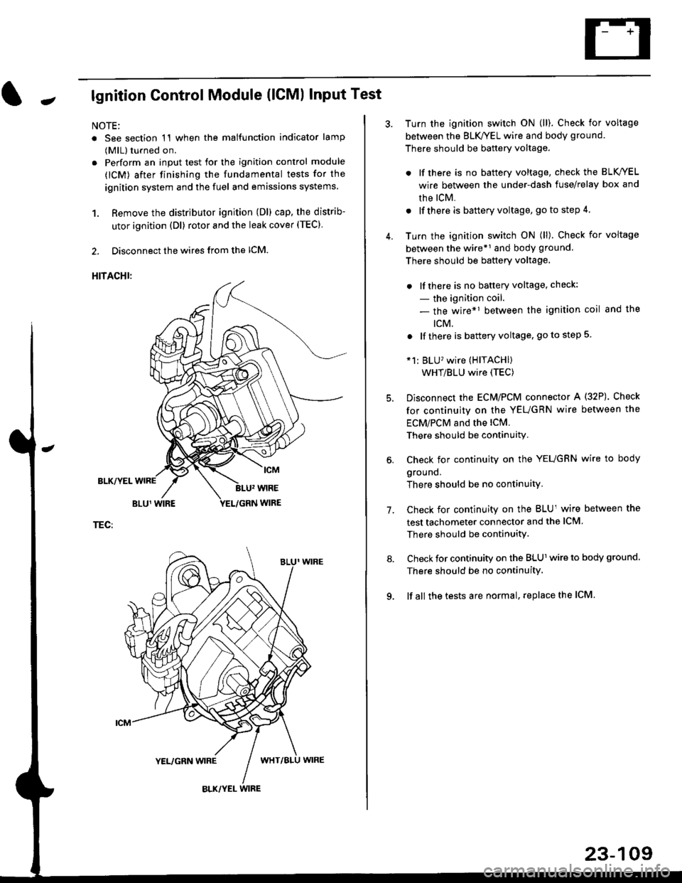
Jlgnition Control Module (lCMl Input Test
NOTE:
. See section 1'l when the malfunction indicator lamp
(MlL) turned on.
. Perform an input test for the ignition control module
(lCM) after finishing the fundamental tests for the
ignition system and the fuel and emissions systems
1. Remove the distributor ignition (Dl) cap, the distrib-
utor ignition (Dl) rotor and the leak cover (TEC).
2. Disconnect the wires from the lCM.
HITACHI:
BLK/YEL
TEC:
Turn the ignition switch ON (ll). Check for voltage
between the BLK/YEL wire and body ground.
There should be battery voltage.
. lf there is no battery voltage, check the BLK/YEL
wire between the under-dash fuse/relay box and
rhe lcM.
. lf there is battery voltage, go to step 4.
Turn the ignition switch ON (ll). Check for voltage
between the wire*r and body ground
There should be battery voltage.
. lfthere is no battery voltage, check:
- the ignition coil.
- the wire*1 between the ignition coil and the
tcM.
. lf there is battery voltage, go to step 5
*1: BLU'wire (HITACHI)
WHT/BLU wire (TEC)
Disconnect the EcM/PCM connector A (32P). Check
for continuity on the YEUGRN wire between the
ECM/PCM and the lCM.
There should be continuity.
Check for continuity on the YEUGRN wire to body
ground.
There should be no continuity.
Check for continuity on the BLUl wire between the
test tachometer connector and the ICM
There should be continuitY.
Check for continuity on the BLUl wire to body ground.
There should be no continuity.
lf all the tests are normal, replace the ICM
7.
23-109
Page 1586 of 2189
Charging System
Troubleshooting (cont'd)
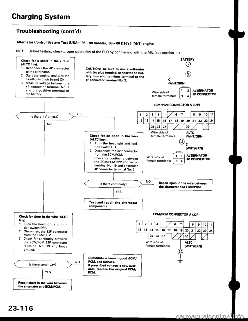
Alternator Control System Test (USA): ,96 - 98 modets, ,99 _ 00 Dl6y5 (M/Tl engine
NorE: Before testing. check proper operation of the ELD by confirming with the MrL {see section r 1).
BATTERY
CAUTION: Be 3ure to use a voltmot€.with its plus terminal connected to b.t-tery plus and its minus terminal to the{P connectoi tgmrinal No. 2.c
{WHT/GRNt
Wire side oIfemale terminals
ALTERNATOR.P CONNECTOB
Check for a 3hort in the circuitIALTC linel:1. Reconnect the 4P connectorto the alternator,2. Stan the engine, and turn theheadlights {high beam) ON.3. Measure voltage between the4P connector terminal No. 2and the positive terminal ofthe battery.
ls there 1V or less?
Check for rn opon in tha wire(ALTC linol:1. Turn the headlight and igni-tion switch OFF.2. Disconnect the 32P connectortrom the ECM/PCN4.3. Check tor continuity betweenthe ECM/PCM 32P connectorterminal No. 19 and alternator4P connector terminal No. 2.
Bspair open in thg wire lrstweenthe rhern.tor .nd ECM/PCM.
Check for short in the wire (ALTClinel:1. Turn the headlight and ignition switch OFF.2. Disconnect the 32P connectortrom the ECM/PCM.3. Check tor continuity betweenthe ECM/PCM 32P connectorterminal No. 19 and bodyground.
Subslitute a known-good ECM/PCM, .nd .och6ck.It p.escribod vohago i! now avail-able, replace the original ECM/PCM.
Ropair 3hort in the wiro betweonthe ahe.nator and ECM/PCM.
ECM/PCM CONNECTOR A I32PI
'Ia18I1011
121314151718t9
7
202'l2221
262730
Wire side offemale terminalsALTC(WHT/GRNI
c{WHT/GRNI
ALTERNATORWire side oIfemale terminals
([l
T
12
1
ECM/PCM CONNECTOB A (32PI
I23478910t1
1213 14151617182021222321
262730
Wire side of I AITCfemate terminats
A
(WHT/GRN|
23-116
Page 1587 of 2189
-
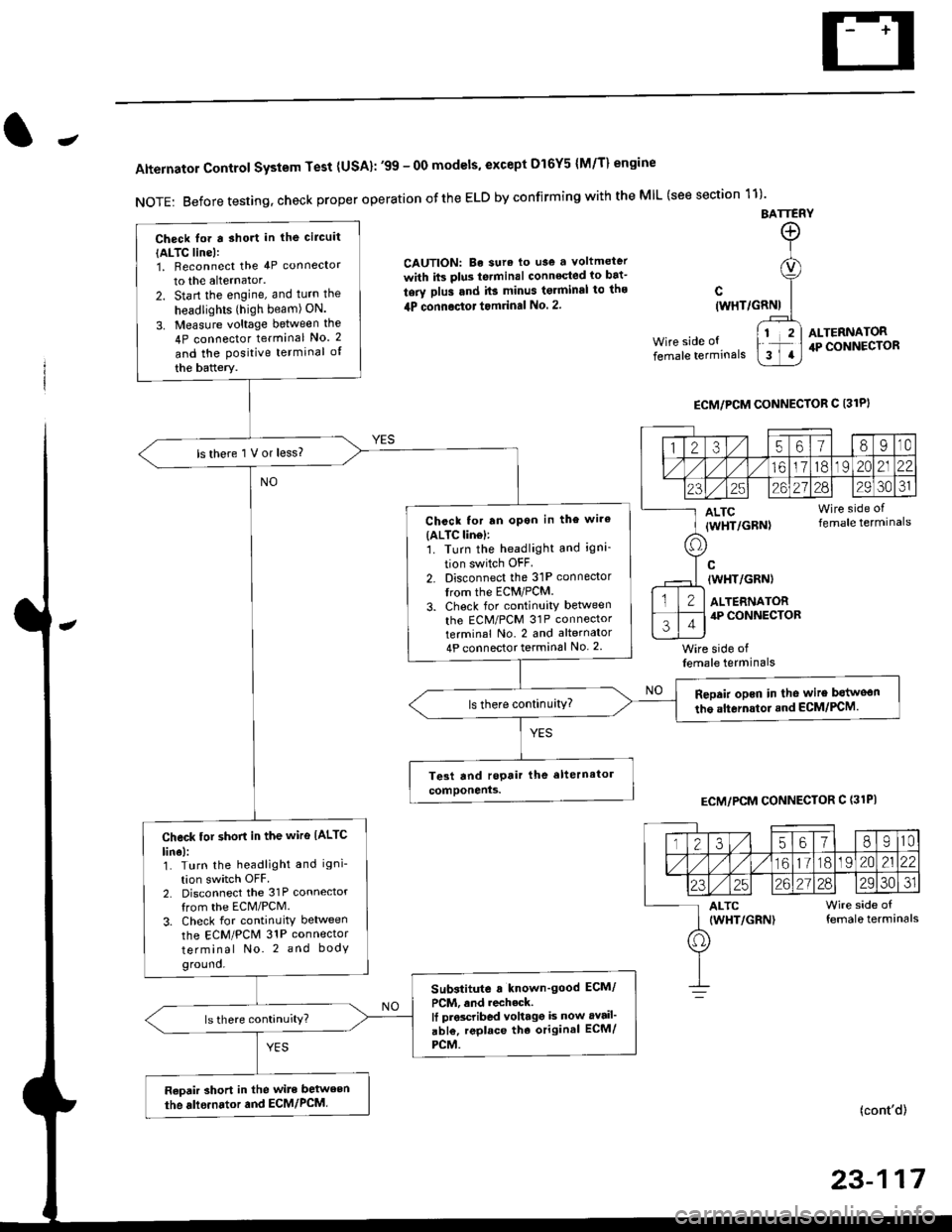
Alternator Control System Test {USA}: '99 - 0O models, except Dl6Y5 {M/T} engine
NOTE: Before testing, check proper operation ofthe ELD by confirming with the MIL (see section 11)'
BATTERY
CAUTION: Be sura lo use a voltmeter
with its plus te.minal conneqted io bat-
tery plus and it3 minus tgrminal to ths
4P connoctot tomrinal No. 2.
Wire side of
female terminals
c(WHT/GRNI
wire side offemale terminals
ALTERNATOR.P CONNECTOR
ECM/PCM CONNECTOR C 13lPI
ECM/PCM CONNECTOR C (31PI
(cont'd)
23-117
Check lor a sho.t in the circuit
{ALTC line):1, Beconnect the 4P connector
to the alternator.
2. Start the engine, and turn the
headlights (high beam) ON.
3. Measure voltage between the
4P connector terminal No. 2
and the Positive terminal of
the battery.
ls there 1 V or less?
Chcck for rn opon in the wire(ALTC lin6l:1. Turn the headlight and igni-
tion switch OFF
2. Disconnect the 31P connector
trom the ECM/PCM.
3. Check for continuity betlveen
the ECM/PCM 31P connectorterminal No. 2 and alternator
4P connector terminal No. 2
Repair opcn in the wire botweon
the alternstoi.nd ECM/PCM.ls there continuity?
Check tor short in the wire IALTC
line):1. Turn the headlight and igni-
tion switch OFF2. Disconnect the 31P connector
from the ECM/PCM.
3. Check for continuity between
the ECM/PCM 31P connector
terminal No. 2 and body
ground.
Substitute a known'good ECM/
PCM, and recheck.It prscribed voltagg is now avail'
abl€, replace tho original ECM/
PCM.
Raoair short in the wite between
the alle.nator and ECM/PCM,
1235618I10
/11611lo191 zo2122
23252621?82930JI
ALTC Wire side of(WHT/GRN) female terminals
o
Page 1611 of 2189
J
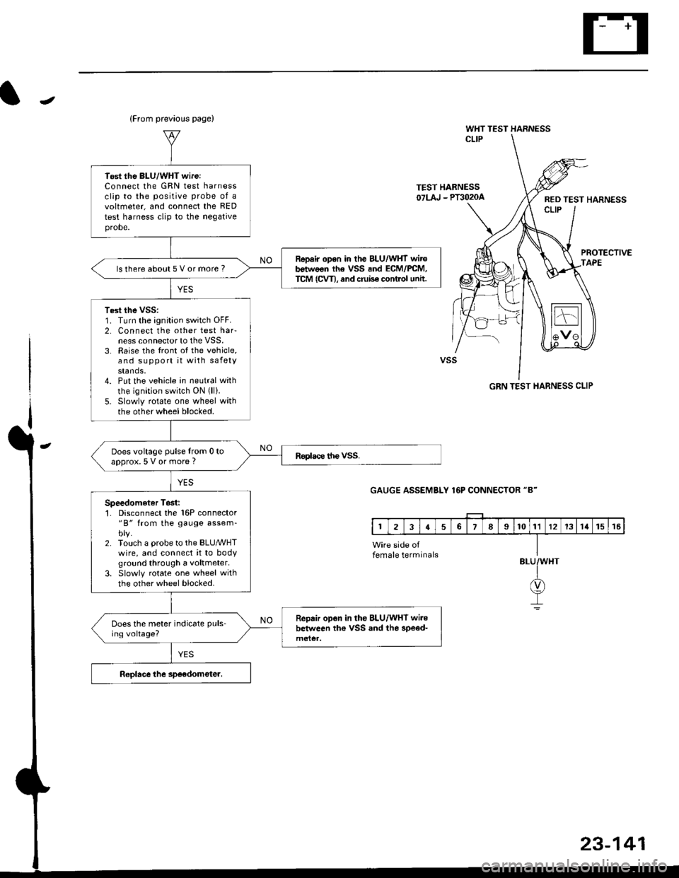
(From prevaous page)
WHT TEST HARNESSCLIP
TEST HABNESS07LAJ - Plil020aRED TEST HARNESSCLIP
PROTECTIVEAPE
GRN TEST HARNESS CLIP
GAUGE ASSEMBLY 16P CONNECTOR "8"
BLU
23-141
Tost the BLU/WHT wireiConnect lhe GRN test harnessclip to the positive probe of avoltmeter, and connect the RED
test harness clip to the negativeprobe.
Repair open in the BLU/WHT wirob€twoon the VSS and ECM/PCM,TCM (CVT), and cruise control untt.ls there about 5 V or more ?
Test the vss:1. Turn the ignition switch OFF.2. Connect the other test harness connector to the VSS.3. Raise the front ot the vehicle,and support it with safetystands,4. Put the vehicle in neutral with
the ignition switch ON (ll).
5. Slowly rotate one wheel withthe other wheel blocked.
Does voltage pulse from 0 toapprox.5 V or more ?
Speedometer Tosii'1. Disconnect the 16P connector"B" from the gauge assem-blv.2. Touch a probe to the BLUMHTwire, and connect it to bodyground through a voltmeter.
3. Slowly rotate one wheel with
the other wheel blocked.
Repair open in the BLU/WHT wi.ebelween th€ VSS and the 3pe€d-Does the meter indicate puls-
ing voltage?
female terminals