Page 730 of 2189

Symptom-to-Component Ghart
Electrical System -'gG - 98 Models
*1: The DTC in the parentheses is the code E indicator light indicates when the Data Link connector is connected to theHonda PGM Tester.*2: Whenever the Honda PGM Tester or Scan Tool detects an automatic transmission control system DTC, p07OO will beset in the PGM-FI control svstem.
DTCIIE Indicaior
LightMILDotection ltemPage
P1753
fl)BlinksONLock-up control solenoid valve A14-56
P1758
\21BlinksONLock-up control solenoid valve B14-58
P1705
(51BlinksONAy'T gear position switch (short to groundl14-60
P1706
(6)OFFONA,/T gear position switch (open)14-62
P0753
l7lBlinksONShift control solenoid valve A14-64
P0758
{8)ElinksONShift control solenoid valve B14-66
POl20
(9)BlinksONCountershaft speed sensor14-68
P0715
{15)
'96 - 97
models:
OFF'98 model:
Blinks
ON
Mainshaft speed sensor
14-70
P1768
{16)BlinksONLinear solenoid't 4-72
P0740
(40)OFFONLock-up control system14-7 4
P0730
(41)OFFONShift control system14-75
P0700*,
(none)Automatic transmission control svstem in the pGM-Fl
control svstem
14-52
Page 732 of 2189

Symptom-to-Component Chart
Electrical System -'99 - 00 Models
*1: The DTc in the parentheses is the code E indicator tight indicates when the Data Link connector is connected to theHonda PGM Tester.*2: Whenever the Honda PGM Tester or scan Tool detects an automatic transmission control system DTc, p07oo will beset in the PGM-FI control svstem
DTC*IE Indicator
LightMILDotostion ltemPage
P1753
fi)BlinksONLock-up control solenoid valve A'14-80
P1758
t2lBlinksONLock-up control solenoid valve B14-82
P1705
{5}BlinksONAy'T gear position switch {short to ground)14-84
P1706
(6)OFFONy'VT gear position switch {open)14-81
P0753
\71BlinksONShift control solenoid valve A14-89
P0758
(8)BlinksONShift control solenoid valve B14-9r
P0720
(9)BlinksONCountershaft speed sensorr4-93
P0715
(15)B linksONMainshaft speed sensor14-95
P1768
(16)BlinksONLinear solenoid't 4-97
PO7 40(40)OFFONLock-up control system14-99
P0730
(41)OFFONShift control svstem14- 100
P0700*,
(none)OFFAutomatic transmission control system in the pGM_Fl
controt svstem
14-54
Page 734 of 2189

Electrical Troubleshooting (,96 - gg Models)
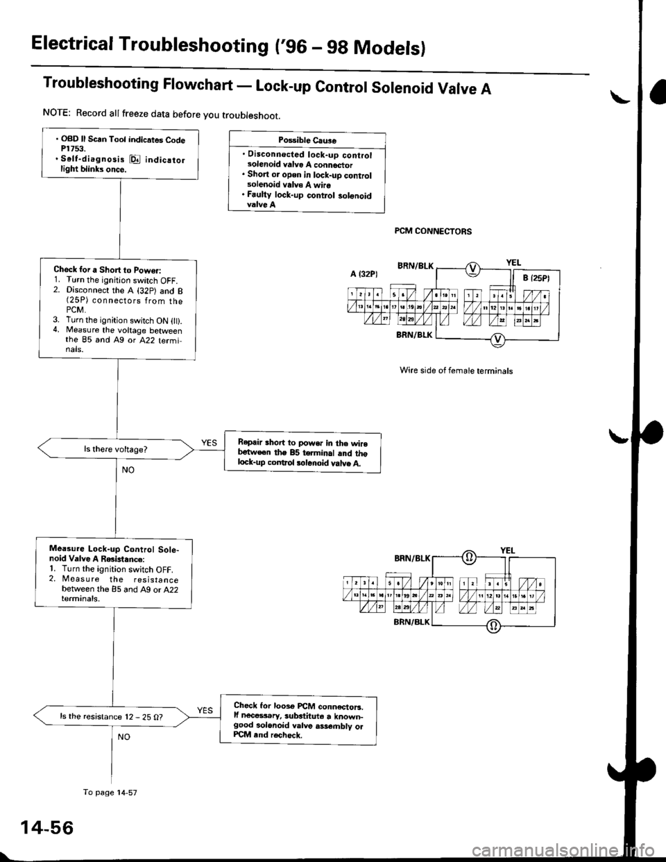
Troubleshooting Flowchart - Lock-up contror sorenoid Varve A
Po$ible Cau3e
. Disconnecled lock-up controlsolenoid valvo A connector. Short or open in lock-uD controlsolenoid valv€ A wire. Fauliy lock-up contlol solonoidvalve A
PCM CONNECTORS
Wire side of female terminals
. OBD ll Scrn Toot indicates CodeP1753.. Self-diagnosis @ indicatorlight blinks once.
Check for a Short to Powo.:1. Turn the ignition switch OFF.2. Disconnect the A (32p) and B(25P) connsgl6ps 1rq- thaPCM.3. Turn the ignition swjtch ON 0t).4, Measure the voltage betweenthe 85 and Ag or A22 terminals.
Repair shoit to power in the wirebetw€en the 85 terminal and thglock-up coDtrol tolenoid valve A.
Mea3ure Lock-up Control Sole-noid Valve A RGislance:'1. Turn the ignition switch OFF.2. Measure the resistancebetween the 85 and A9 or A22terminals.
Check lor looso PCM conn€ctoB.lf nece$.ry, substituto a known-good aolonoid valve ass€.nblv olPCM end rech6ck.
ls the resistance 12 - 25 O?
NOTE: Record allfreeze data before you troubleshoot.
A l32P)
To page'14-57
Page 735 of 2189
From page 14-56
Ch6ck Lock-up Control Solenoid
Valve A tor a Short Cilcuiti
1. Disconnect the 2P connector
lrom the lock-up control sole-
noid valve assemblY.2. Check for continuity between
the 85 and Ag or A22 termi-
nats.
Ropair 3hort to giound in iha wila
b.twoqn th6 85 terminrl rnd tho
locl-up control 3olanoid valvo A.
Mo..ura Lock-up Control Sole'
noid Velve A Reri3tanc. at tho
Solenoid Conn6cto.:Measure the resistance betweenthe No. 2 terminal of the lock-up
control solenoid connector and
body ground.
Chock for opan in tha wit.
ba(w.an tha 85 torminll lnd the
lock-uo control lolanoid vtlYa A.ls the resistance 12 _ 25 O?
Roplsce tho lock"up cont.ol 3ol€_
noid vllvo arsembly.
PCM CONNECIOBS
Wire side of lem6leterminals
LOCK.UP CONTROLSOrINOID CONNECTOR
YEL
Teaminal side of malo terminals
lml-,f
(o)
I
14-57
Page 736 of 2189

Electrical Troubleshooting ('96 - 9g Modelsl
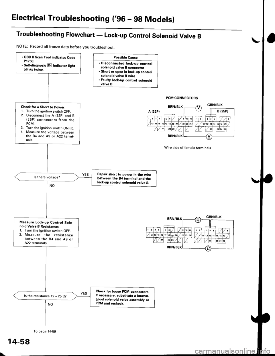
Troubleshooting Ftowchart - Lock-up control sorenoid Varve B
Possible Cause
. Disconnected lock-up controlsolenoid valve B connector' Short or open in lock-up controlsolonoid valve B whe. Faulty lock-up control solenoidvalve B
PCM CONNECTORS
Wire side of female terminals
. OBD ll Scan Tool indicrtes CodeP1758.. Self-diagnosis E indicrtor lightblinkstwice.
Check for a Shon to Power:1. Turn the ignition switch OFF.2. Disconnect the A (32p) and B(25P) connectors from thePCM,3. Turn the ignition switch ON t).4. Measure the voltage betweenthe 84 and A9 or A22 termi-nals.
Repeir short to power in the wirebetween the 84 teiminal and thelock-up control solenoid valve B.
Moasure Lock-up Control Sole-noid Valve B Resistance:1. Turn the ignition switch OFF.2. Measure the resistancebetween the 84 and Ag orA22 terminals.
Check for loose FCM connectors,lf necessary, substitute a known-good solenoid valve assembly olP1CM and rech6ck.
ls the resistance 12 - 25 O?
NOTE: Record all freeze data before you troubleshoot.
A {32P)
To page 14-59
t-
Page 737 of 2189
From page 14 58
Check Lock-up Control Solenoid
Valve B for a Short Circuh:
1. Disconnect the 2P connector
from the lock-uP control sole'
noid valve assefibly.
2. Check for continuity between
the 84 and A9 or A22 terma-
nals,
Rgprir 3hort to ground in tho wite
Hwoon the 84 torminal and the
lock-uo contlol solonoid valvs B.ls there continuity?
Measu.o Lock-uP Control Sole'
noid Valve I Resistance at tho
Solenoid Connector:Measure the resistance between
the No. 1 terminal o{ the lock-up
control solenoid connector and
body ground.
Chcck tor opcn in the wirs
b€tlve.n the 84 ierminal and tho
lock-up conttol solonoid vllvc B.ls the resistance 12 - 25 O?
Reolace the lock'up control sole-
noid valve assemblY.
PCM CONNECTORS
Wire side oI lemale terminals
LOCK.UP CONTROL
SOLENOID CONNECTOR
IFl;II-r:-]
6nn/eLKfi
I
Terminal sido ot male terminals
14-59
Page 752 of 2189

Electrical Troubleshooting ('96 - 98 Models)
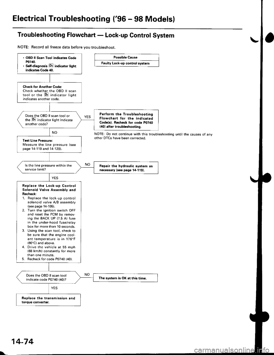
Troubleshooting Flowchart - Lock-up Control System
NOTE: Record all freeze data before vou troubleshoot.
Possible Cause
Faulty Lock-up cont.ol system
NOTE: Do not continue with this troublesnoonnoother DTCS have been corrected.until the causes of any
. OBD ll Sc6n Tool indicatG Codem7{0.. Self-diagnosis E indicator lightindicates Code 40.
Check tor Another Code:Check whether the OBD ll scantool or the E indicato, lightindicates another code.
Perform lhe Troublo3hooiingFlowchart tor the indicatedCode(s). Recheck for cod. P07il0lilol aftor iroubl€3hooting.
Does the OBD ll scan tool orthe E indicator light indicateanother code?
Tast Line Pressure:Measure the line pressure (seepage 14-119 and 14-120).
Repair tho hydreulic aystem a3necessary {3ee page 14-119).
Replace the Lock-up ControlSolenoid Valve Assembly andR6check;1. Beplace the lock up controlsolenoid valve Ay'B assembly(see page 14-105).2. Turn the ignitaon switch OFFand reset the PCM by removing the BACK UP (7.5 A) fusein the underhood fuse/relaybox for more than 10 seconds,3. Using the scan tool, check tobe sure that the engine coolant temperature is in 176'F(80'C) and above.4. Drive the vehicle at 55 mph(88 km/h) constantly for morethan one minute.5. Recheck for code P0740 (40).
Does the OBD ll scan toolindicate code P0740 {40)?The systom k OK at this time.
l'.
14-74
Page 758 of 2189

Electrical Troubleshooting ('99 - 00 Models)
Troubleshooting Flowchart - Lock-up Control Solenoid Valve A
NOTE: Record all freeze data before vou troubleshoot.
Possible Cause
. Disconnocted lock-uD controlsolenoid valve A/B alsemblyconnector. Short or opon in lock-up conkolsolenoid valv6 A wire. Faulty lock-up control solenoidvalva A' Open in VB SOL wireFCM CONNECTORS
LGl IBRN/BLXI LG2 (BRN/BLK)
Wire side ot female terminals
LGl (BRN/BLKILG2 IBRN/8LK)
To page 1+81
a\
. OBD ll Scan Tool indic.t6 CodeP1753.. Self-diagnosis @ indicatorlight blink3 once.
Check lor a Short to Power:L Turn the ignition switch OFF.2. Disconnect the B (25P) and D(16P) connectors lrom thePCt\4.3. Turn the ignition switch ON (ll).4. Measure the voltage betweenthe Dl and 820 or 822 termi-nats.
Ropair short to powcr in the wirebstwoon tho Dl tolminal and thelock-up cor|lrol lolonoid valvo A.
Measu.e Lock-up Cont.ol Sole-noid V.lvo A R63btanc6:1. Turn the ignition switch OFF.2. Measure the resistancebetween the Dl and 820 or822 terminals.
ls the resistance 12 - 25 O?
Measure VB SOL Vohage:1. Turn the ignition switch ON (ll).2. Measure the voltage betweenthe D5 and 820 or 822 termi-nals.
Check for blown No. 15 17.5 Alfu3€ in the undordash fuse/rabybox. l{ th€ tusa ii OK, r.pair oponin the wira b€twoen th€ 05 torfti-nal and thc und€r{ash fuso/r€laybox.
Check to.loose tarminalfit in thePCM connecloa3. ll necessary,substilute a known-good PCMand rocheck.
B (25Pt ll D {16P1
B (2sPt ll D {16P1
I t25Pt D (16P1
l..
14-80