Page 1142 of 2189
Front Damper
Disassembly/lnspection
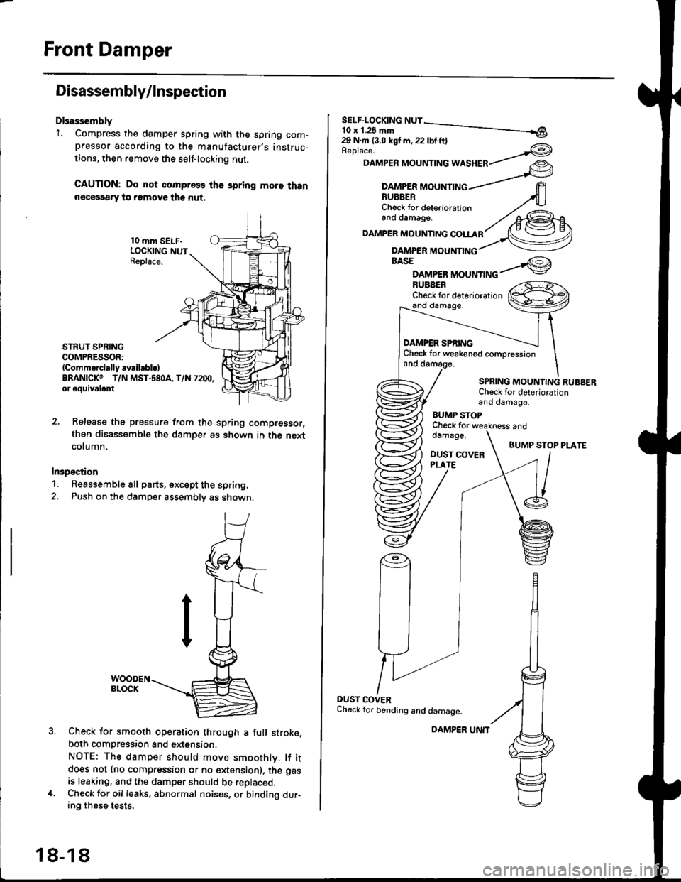
Disassembly'1. Compress the damper spring with the spring com-pressor according to the manufacturer,s instruc-
tions, then remove the self-lockino nut.
CAUTION: Do not compress the spring more thann€cessary to remove the nut.
10 mm SELF-LOCKING NUTReplace.
STRUT SPRINGCOMPRESSOR:(Commerci.lly availabl.lBRANICKO T/N MST.s8I}A, T/N 7200,or eouivalent
Release the pressure from thg spring compressor,
then disassemble the damper as shown in the next
column.
Inspostion
1. Reassemble all parts, except the spring.
2. Push on th€ damper assembly as shown.
Check for smooth operation through a full stroke,
both compression and extension,
NOTE: The damper should move smoothlv. lf itdoes not (no compression or no extension), the gas
is leaking, and the damper should be replaced.Check for oil leaks, abnormal noises, or binding dur-ing these tests.
18-18
DAMPER UNIT
Replace.
DAMPER MOUNTING WASHER
BASE
DAMPER MOUNTINGBUBBERCheck for deteriorationand damage.
DAMP€R SPf,INGCheck tor weakened compressionand damage.
SPBING MOUNTING RUBBERCheck for deteriorationand damage,
BUMP STOPCheck fordamage.
DUST COVERPLATE
and
BUMP STOP PLATE
OUST COVERCheck for bending and damage.
Page 1150 of 2189
Rear Damper
Removal
1. Bemove the rear wheels (see page 1g-22).
2. Remove the speaker cover and speaker (Hatchback).
Sedan and Coupe: Remove the trunk side panel (see
section 20).
3. Remove the two flange nuts.
FLANGE NUTS10 x 1.25 mm
4. Remove
FLANGE BOLT10 x 1,25 mm
Remove the flange bolt that connects the lower armto the trailing arm.
the flange bolt from the damper.
FLANGE BOLT'10 x 1 .25 mm
18-26
6. Lower the rear suspension, and remove the damper.
Page 1152 of 2189
Rear Damper
Disassembly/lnspection (cont'dl
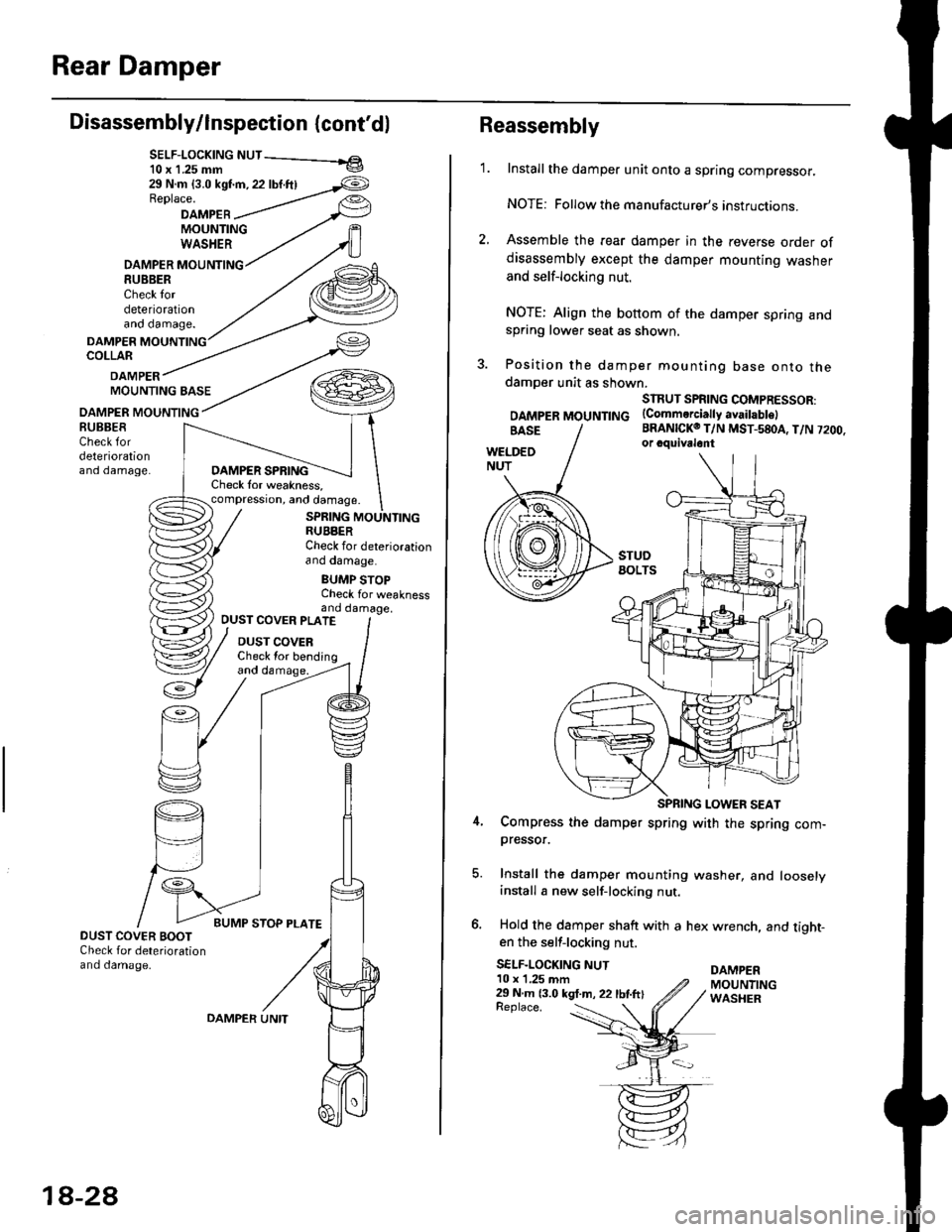
SELF-LOCK|NG NUT - el10 x 1.25 mm v
29 N.m {3.0 kst'm, 22 lbf.ftlReplace.
DAMPEBMOUNTINGWASHER
DAMPER MOUNTING8U8BERCheck tordeteriorationano oamage.
DAMPERCOLLAR
DAMPERMOUNTING BASE
OAMPER MOUNTING
DAMPER SPRINGCheck lor weakness,compression, and damage.
SPRING MOUNTINGRUBBERCheck for deteriorationano oamage.
BUMP STOPCheck for weaknessand damage,
BUBBESCheck fordeteriorationano oamage.
OUST COVER PLATE
DUST COVERCheck lor bending
DUST COVER BOOTCheck for deteriorationand damage.
18-2A
OAMPER UNITReplace. :
Reassembly
1.Install the damper unit onto a spring compressor.
NOTE: Followthe manufacturer's instructions.
Assemble the rear damper in the reverse order ofdisassembly except the damper mounting washer
and self-locking nut.
NOTE: Align the bottom of the damper spring andspring lower seat as shown.
Position the damper mounting base onto thedamoer unit as shown.
SIRUT SPRING COMPRESSOR:
DAMpERMOUNTTNG (Commerciattyavaitabtel
BRANICKO T/N MST-580A, T/N 7200.or cquivalont
Compress the damper spring with the spring com-pressor.
Install the damper mounting washer, and looselyinstall a new self-locking nut.
Hold the damper shaft with a hex wrench, and tight-en the self-locking nut.
SELF-LOCKING NUTDAMPER10 x 1,25 mm29 N m 13.0 kgt.m, 22 lbtftlMOUNTINGWASHER
Page 1158 of 2189
Inspection and Adjustment
€)
@
@
@
Brake System Rubber Parts and Brake Booster
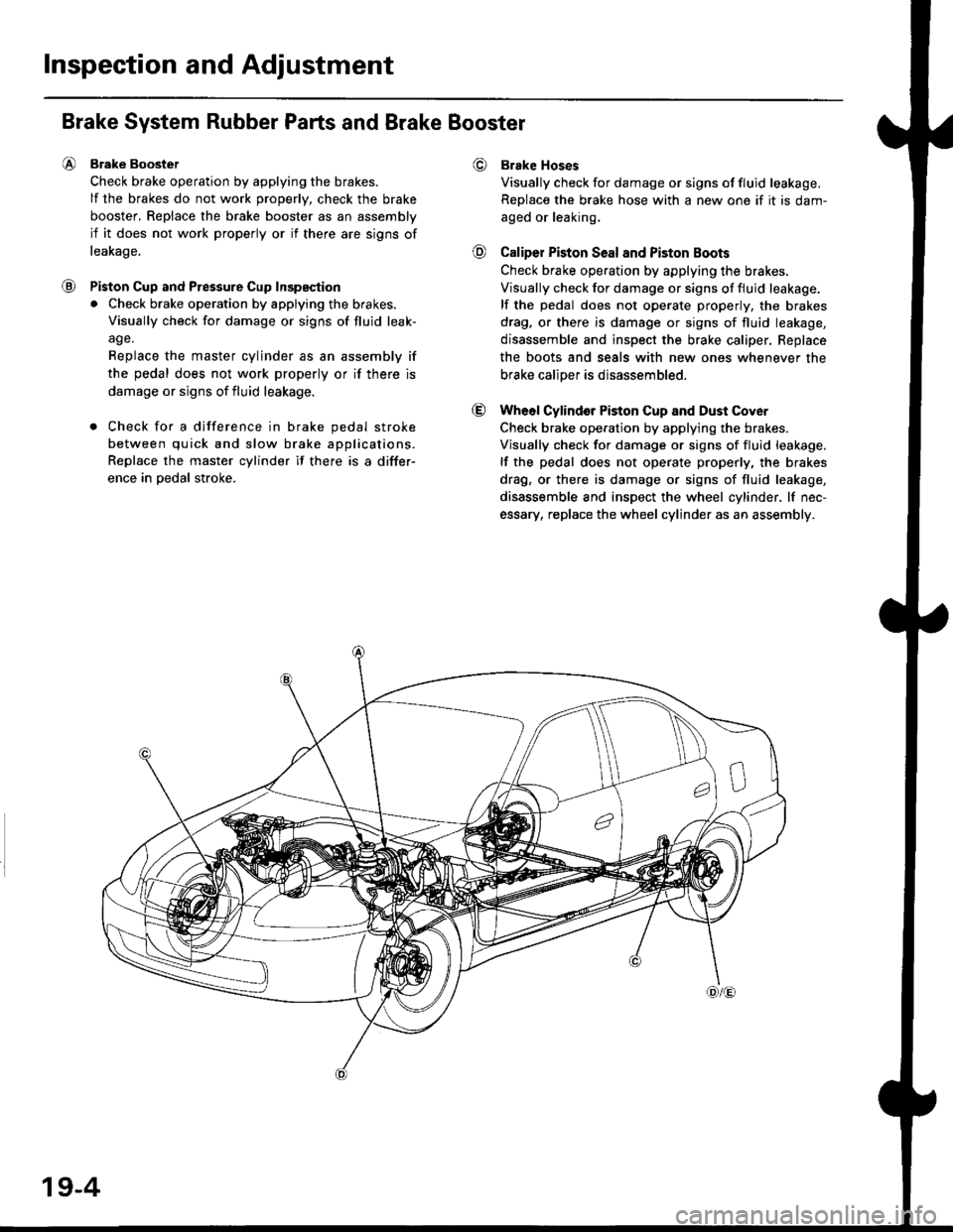
Brake Boostet
Check brake operation by applying the brakes.
lf the brakes do not work properly, check the brake
booster, Replace the brake booster as an assembly
if it does not work properly or if there are signs of
leakage.
Piston Cup and Pressure Cup Inspeqtion
. Check brake operation by applying the brakes.
Visually check for damage or signs of fluid leak-
age.
Replace the master cylinder as an assembly if
the pedal does not work properly or if there is
damage or signs of fluid leakage.
. Check for a difference in brake pedal stroke
between quick and slow brake applications.
Replace the master cylinder if there is a differ-
ence in oedal stroke.
Brake Hoses
Visually check for damage or signs of fluid leakage.
Replace the brake hose with a new one if it is dam-
aged or leaking.
Caliper Piston Seal and Piston Boots
Check brake ope.ation by applying the brakes.
Visually check for damage or signs of fluid leakage.
lf the pedal does not operate properly, the brakes
drag. or there is damage or signs of fluid leakage,
disassemble and inspect the brake caliper. Replace
the boots and seals with new ones whenever the
brake caliDer is disassembled.
Wheol Cylindor Piston Cup and Dust Cover
Check brake operation by applying the brakes.
Visually check for damage or signs of fluid leakage.
lf the pedal does not operate properly, the brakes
drag, or there is damage or signs of fluid leakage,
disassemble and inspect the wheel cylinder. lf nec-
essary, replace the wheel cylinder as an assembly.
19-4
Page 1168 of 2189
Front Brake Caliper
2056 Type:
@
Disassembly (cont'dl
Nevor u3e an air hos€ or dry brush to clgan brake
assomblios.
Use an OSHA approved vacuum cl6aner to avoid
braathing braks duet.
CAUTION:
. Do not spill brakefluid on ths vchicle; it may damage
the paint; if brako fluid does contact the p.int. wash
it olt immediately with wato..
. To prevsnt spills, cover the ho3o ioints whh rag3 or
shop towels.
. Cl€an all parts in brake fluid and air dry; blow out 8ll
passagss with compr63€d air.
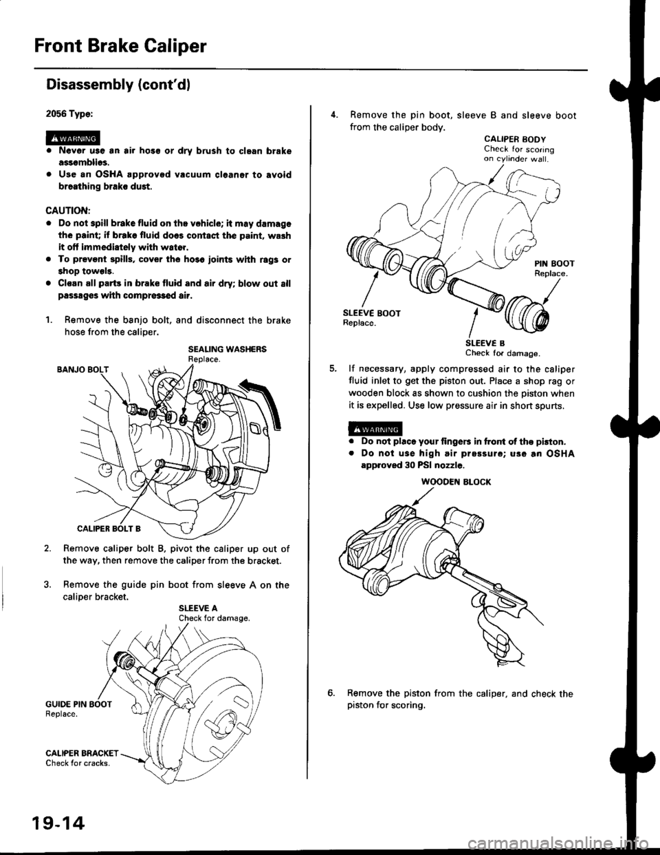
1. Remove the banjo bolt, and disconnect the brake
hose from the caliper.
SEALING WASHERS
Remove caliper bolt B, pivot the caliper up out of
the way, then remove the caliper from the bracket.
Remove the guide pin boot from sleeve A on the
caliDer bracket.
GUIDE PIN BOOTReplace.
GALIPER BRACKETCheck tor cracks.
Check for damage.
19-14
4. Remove the pin boot, sleeve B and sleeve boot
from the caliper body.
CALIPER EODYCheck for scoringon cytinder wa .
SLEEV€ BCheck for damage.
lf necessary, apply compressed air to the csliper
fluid inlet to get the piston out. Place a shop rag or
wooden block as shown to cushion the oiston when
it is expelled. Use low pressure air in short spurts,
a
a
Do not placo your lingers in ftont ol tho pkton.
Do noi usa high air prsssure; uso an OSHA
approved 30 PSI nozzle.
Remove the piston from the caliper, and check thepiston for scoring.
WOODEN ALOCK
Page 1175 of 2189
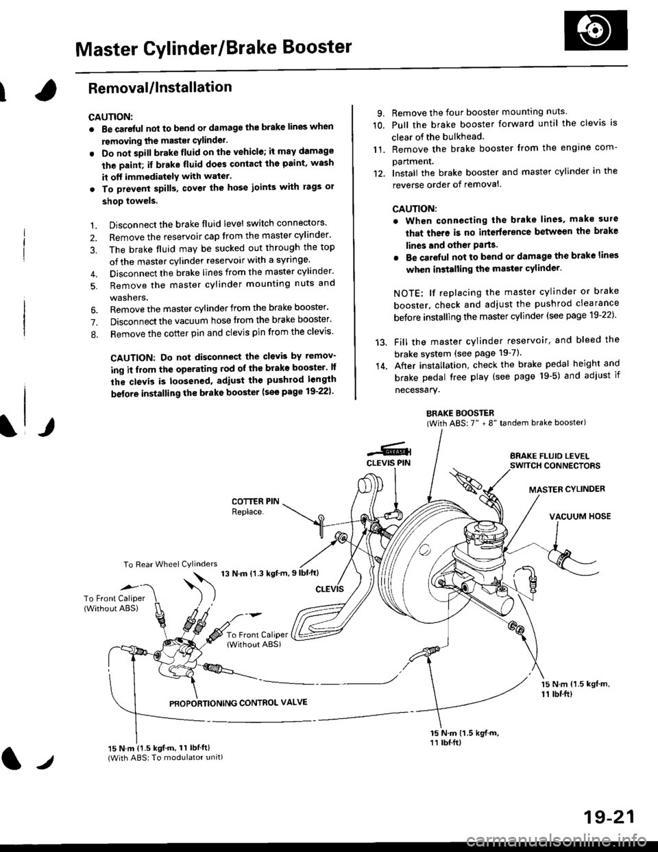
Master Cylinder/Brake Booster
IRemovaUlnstallation
CAUTION:
. Be care{ul nol to bend or damage the brake lines when
rsmoving the mastsr cYlinder.
. Do not soill brakefluid on the vehicle; it may damage
the paint; if brake fluid does contact the paint, wssh
it off immediatelY with water'
. To prevent spill3, cover the hose ioints with rags or
shop towels.
9. Remove the four booster mountlng nuts
10. Pull the brake booster forward until the clevis is
clear of the bulkhead.
11. Remove the brake booster from the engine com-
panmenr.'12. Install the brake booster and master cylinder in the
reverse order of removal.
CAUTION:
. When connecting the brake lines. make sure
that there is no inte erence between the brake
lines and oth6r Parts.
r Be careful not to bend or damage the brake lines
when installing the master cylinder.
NOTE: lf replacing the master cylinder or brake
booster, check and adiust the pushrod clearance
be{ore installing the master cylinder (see page 19-221'
Fill the master cylinder reservoir, and bleed the
brake svstem (see Page 19-7).
After installation. check the brake pedal height and
brake pedal tree play (see page l9-5) and adjust if
necessary.
BRAKE BOOSTER(With ABS: 7" + 8" tandem brake booster)
BRAKE FLUIO LEVELSWITCH CONNECTORS
MASTER CYLINDER
VACUUM HOSE
1.
2.
3,
5.
Disconnect the brake fluid level switch connectors'
Remove the reservoir cap from the master cylinder'
The brake fluid may be sucked out through the top
of the master cylinder reservoir with a syrlnge.
Disconnect the brake lines from the master cylinder'
Remove the master cylinder mounting nuts and
washers.
\l/
6. Remove the master cylinder from the brake booster'
7. Disconnect the vacuum hose trom the brake booster'
8. Remove the cotter pin and clevis pin from the clevis'
CAUTION: Do not disconnect the clevb by remov-
ing it from the operating rod of the brako booster' lf
the clevis is loosened, adiust the pushrod length
before installing th€ brake booster (see page 19-221'
COTTER PINReplace.
To Rear Wheel Cylinders
14.
-6.4CLEVIS PIN
To Front Caliper(Without ABS)$
t'N't'ttrnt'-''
To Front CaliperlWithout ABSi
PBOPORTIONING CONTROL VALVE
15 N.m {1.5 kgl m,11 tbtft)
15 N.m {1.5 kgif.m, 11 lbtft}(With ABS: To modulator unit)lr
19-21
Page 1181 of 2189
Rear Brake Caliper
Disassembly
@f l',lever use an air hose or dry brush to clean
assemblies.
. Use an OsHA-approved vacuum cleaner to
brake
avoid
breathing brake dust.
. Contaminated brake discs or pads reduce stopping
ability.
CAUTION:
. Do not spill brake tluid on the cal; h may damage the
paint; if brake fluid does contact the paint, wash ii
ofl immediatelY with water.
. To prevent spills, cover the hose ioints whh rags or
shop tow€ls.
. Clean all parts in brake fluid and air dry; blow out all
passagss with complessed air.
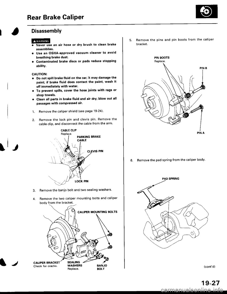
1. Remove the caliper shield (see page 19-24).
2. Remove the lock pin and clevis pin. Remove the
cable clip, and disconnect the cable from the arm
CABLE CLIP
Remove the banjo bolt and two sealing washers
Remove the two caliper mounting bolts and caliper
body from the bracket.
CALIPER MOUNTNG AOLTS
CALIPER BRACKETCheck for cracksSEALINGWASHERSReplace.BANJOBOLT
5, Remove the pins and pin boots from the caliper
bracket.
6. Remove the pad spring from the caliper body
PIN A
(cont'd)
19-27
Page 1182 of 2189
Rear Brake Galiper
Disassembly (cont'd)
7. Remove the piston by rotating the piston counter-clockwise with the tool, and remove the piston
boot.
CAUTION: Avoid damaging the piston.
PISTON BOOTReplace.
Remove the piston seal.
CAUTION: Take care not to damage the cylinderbore.
CALIPER BODYCheck for scoring on
9. Install the special tool between the caliper bodv andspnng cover.
CAUTION: Be caretul not to damags the inside ofthe caliper cylinder during caliper disassembty.
BRAKE SPRINGCOMPRESSOR07HAE - SG00100
11.
LOCKNUTS
Position the locknuts as shown. then turn the shaftuntil the plate just contacts the caliper body.
NOTE: Do not compress the spring under thespring cover.
Turn the shaft clockwise 1/4 -'ll2 tu.n to comoressadjusting spring B in the caliper body.
CAUTION: To preyant damage to the inner compo-nonts. do not turn the shaft mor€ than 1/2 turn.
SHAFT
LOCKNUTS
PISTON SEALReplace.
ADJUSTII{GSPRING 8
19-28