Page 1262 of 2189
Rear Window
Removal
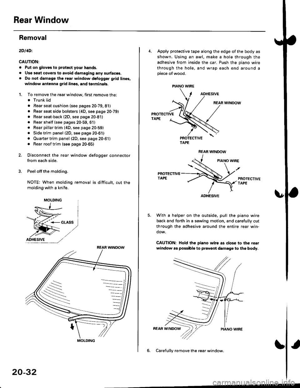
2DllDl
CAUTION:
. Put on gloves to protect your hands.
. Uso ssat covers to avoid damaging any surlaces,. Do not damage thg roar window dofogggr grid linss,
window antenna grid lines, and tsrminalg.
1. To remove the rear window, first remove the:. Trunk lid
. Rear seat cushion (see pages 20-79, 81). Rear seat side bolsters {4D, see page 20-79). Rear seat-back (2D, see page 20-81)
. Rear shelf {see pages 20-59, 61}
. Rear pillar trim {4D, see page 20-59). Side trim panel (2D, see page 20-61)
. Ouarter trim panel (2D, see page 20-61)
. Rear roof trim (see page 20-65)
2, Disconnect the rear window defogger connector
from each side.
3. Peel off the molding.
NOTE: When molding removal is difficult, cut the
molding with a knile.
F"*t,
MOLDING
ID_HESI.VE ---, ,/,/
REAR WINDOW
S
MOLDING
20-32
PIANO WIRE
4. Apply protective tape along the edge of the body as
shown. Using an awl, make a hole through the
adhesive from inside the car. Push the piano wire
through the hole, and wrap each end around apiece of wood.
ADHESIVE
REAR WINDOW
PROTECTIVETAPE
TAPE
REAR WNDOW
PIANO WIRE
PROTECTIVETAPE
With a helper on the outside, pull the piano wire
back and forth in a sawing motion, and carefully cut
through the adhesive around the entire rear win-
dow.
CAUTION: Hold the piano wiro as close to the rear
window as possibls to prcyent damage to the body.
6. Carefullv remove the rear window.
ADHESIVE
Page 1270 of 2189
Rear WindowOuarter Glass
Installation {cont'd)
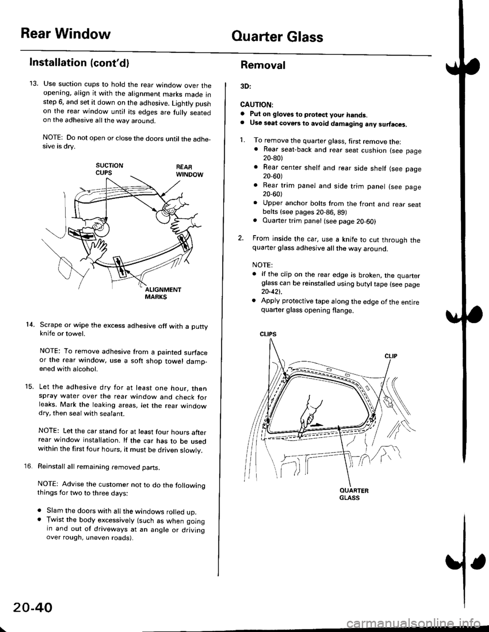
13. Use suction cups to hold the rear window over theopening. align it with the alignment marks made inslep 6. and set it down on the adhesive. Lightly pushon the rea. window until its edges are fully seatedon the adhesive allthe way around.
NOTE: Do not open or close the doors until the adhe_sive is drv.
sucTtoNCUPS
Scrape or wipe the excess adhesive off with a puttyknife or towel.
NOTE: To remove adhesive from a painted surfaceor the rear window. use a soft shop towel damp-ened with alcohol.
Let the adhesive dry for at least one hour. thenspray water over the rear window and check forleaks, Mark the leaking areas, let the rear windowdry, then seal with sealant.
NOTE: Let the car stand for at least four hours afterrear window installation. lf the car has to be usedwithin the first four hours, it must be driven slowly.
Reinstall all remaining removed parts.
NOTE: Advise the customer not to do the followingthings for two to three days:
. Slam the doors with all the windows rolled up.. Tr,vist the body excessively lsuch as when goingin and out of driveways at an angle or drivingover rough, uneven roads).
14.
15.
\
20-40
Removal
3D:
CAUTION:
a Pul on gloves to protect your hands.. Use seat covers to avoid damaging any surfaces,
1. To remove the quarter glass, first remove the:. Rear seat-back and rear seat cushion (see page20_80)
. Rear center shelf and rear side shelf lsee page20_60)
. Rear trim panel and side trim panel (see page20_60)
. Upper anchor bolts from the front and rear seatbelts {see pages 20-86. 89). Ouarter trim panel (see page20-60)
2, From inside the car, use a knife to cut through thequarter glass adhesive all the way around.
NOTE:
. lf the clip on the rear edge is broken, the quarterglass can be reinstalled using butyltape (see page20-421.
. Apply protective tape along the edge of the entirequarter glass opening flange.
OUARTERGLASS
Page 1275 of 2189
Removal
2Oi
CAUTION:
. Put on gloves to protect your hands.
. Use seat covers to avoid damaging any surfaces.
1. To remove the quarter glass, first remove the:
. Rear seat-back and rear seat cushion (see page
20_81)
o Slde trim panel (see page 20-611
. Rear shelf (see page 20-61)
o Upper anchor bolt from the front seat belt (see
page 20-86)
. Ouarter trim panel (see page 20-6'l)
2. From inside the car. use a knife to cut through the
quarter glass adhesive allthe way around.
NOTE:
. lf the quarter glass is to be reinstalled, take care
not to damage the molding.
. Apply protective tape along the edge ofthe entire
quaner glass oPening flange
D
I
GLASS
Upper portion:
ADHESIVE
PROTECTIVETAPE
Rear edge portion:
Pillar portion:
Carefully remove the quarter glass.
NOTE: Check the molding for damage, and replace
it if necessary.
3.
TAPE
20-45
Page 1281 of 2189
Troubleshooting
SymptomProbable Cause
Water leaks1. Clogged drain tube.
2. Gap between glass weatherstrjp and roof panel.
3. Defective or improperly installed glass weatherstrip.
4. Gap between drain seal and roof panel.
Wind noise'1. Excessive clearance between glass weatherstrip and roof panel.
Motor noise1. Loose motor.
2. Worn gear or bearing.
3. Cable assembly deformed.
Glass does not move, but motor turns'1. Clutch out of adjustment.
2. Foreign matter stuck between guide rail and slider.
3. lnner cable loose.
4. Cable assembly not attached properly.
Glass does not move and motor does not turn
{glass can be moved with moonroof wrench)
1. Blown fuse,
2. Faulty switch.
3. Battery run down.
4. Defective motor.
5. Faulty relay.
D
Glass Height Adjustment
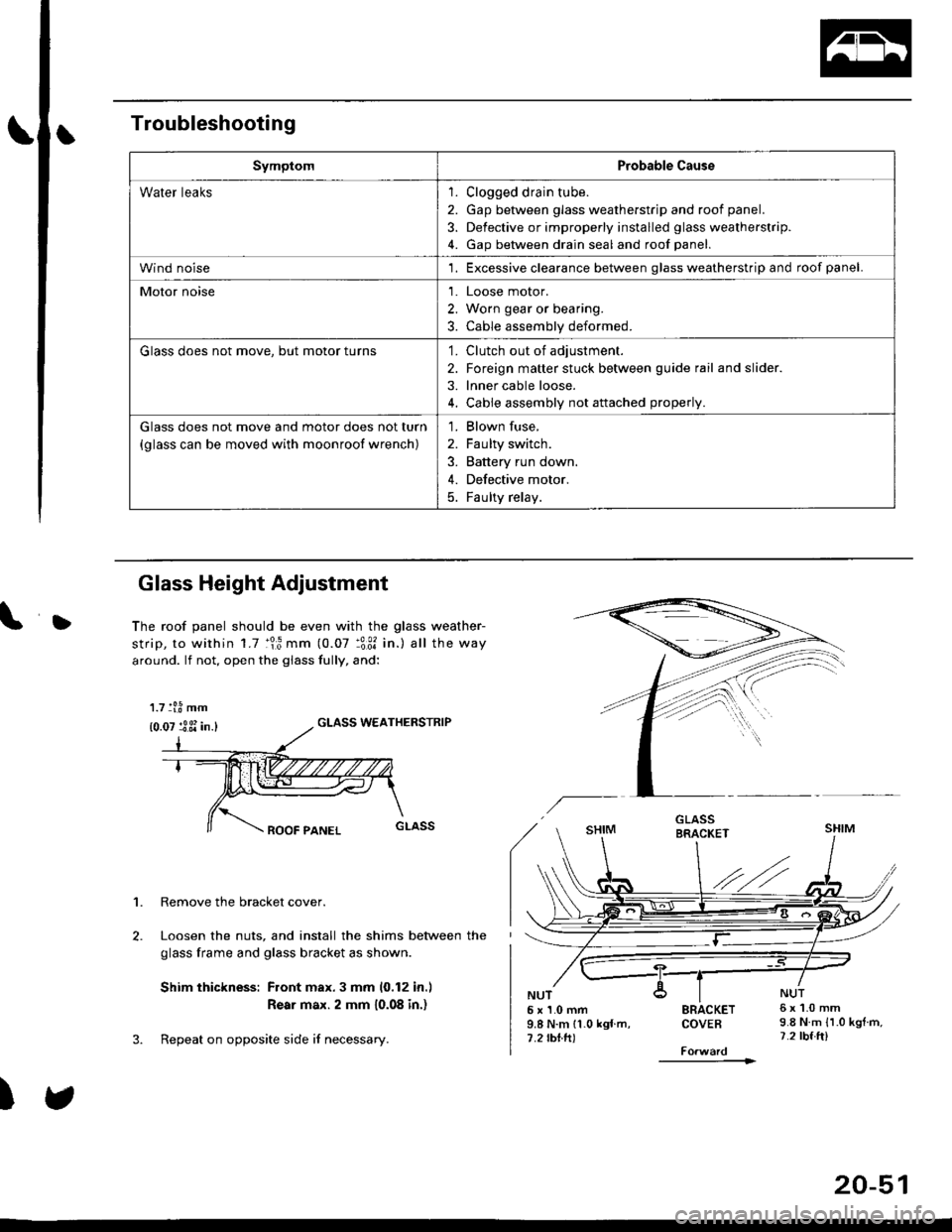
The roof panel should be even with the glass weather-
strip, to within 1.7 :lr3 mm (0.07 :3:31 in.) all the way
around. lf not, open the giass fully, and:
GLASS WEATHERSTRIP
1. Remove the bracket cover.
Loosen the nuts, and install the shims between the
glass frame and glass bracket as shown.
Shim thickness: Front max.3 mm 10,12 in.l
Rear max. 2 mm 10.08 in.)
Repeat on opposite side i{ necessary.
)
5x1.0mm9.8 N.m 11.0 kgf m,7.2 rbtft)
SRACKETCOVEB
----------1>
6x1.0mm9.8 N.m {1.0 kgtm,7.2 tbf.ft)
1.7 tl.8 mm
{0.07 :3 3i in.}
20-51
Page 1282 of 2189
Moonroof
Glass, Glass Bracket and Sunshade Replacement
l. Close the glass fully.
2. Slide the sunshade all the way back.
3. Remove both bracket covers.
Forward_--____->
4. Remove the nuts from both glass brackets.
6x1.0mm9.8 N.m (1.0 kgf.m,7.2lbt.ftl
Remove the glass by lifting up and pulling forward
as shown.
NOTE: Do not damage the roof panet.
ERACKET COVER
GLASS EBACKET
GLASS
\
20-52
DRAIN CHANNEL
6. Remove the drain channel.
7. Remove the holder cover. then remove the
holder B.
NUT6x1.0mm9 N.m {0.9 kgf.m.? tbtftl{i;t'm
RAIL HOLDER B
Using the moonroof wrench, move the glass bracket
to the position where the moonroof normally pivots
down, and remove the screws.
scREws
Page 1296 of 2189
Carpet
Replacement
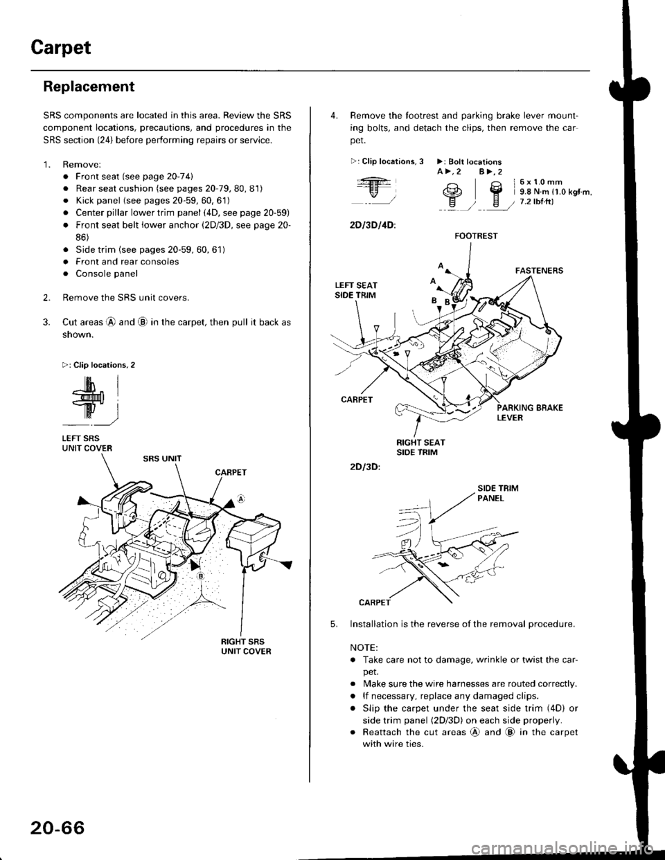
SRS components are located in this area. Review the SRS
component locations, precautions, and procedures in the
SRS section {24} before performing repairs or service.
1. Remove:
. Front seat (see page 2O-7 4l
. Rear seat cushion (see pages 20 79, 80, 81)
o Kick panel (see pages 20-59, 60, 61)
o Center pillar lowertrim panel i4D, see page 20-59)
. Front seat belt iower anchor (2Dl3D, see page 20-
86)
. Side trim (see pages 20-59, 60,61)
o Front and rear consoles
. Console panel
Remove the SRS unit covers.
Cut areas @ and @ in the carpet, then pull it back as
snown.
>: Clip locations,2
2.
3.
-lM- IlMt l
ry-l
LEFT SRSUNIT COVER
20-66
4. Remove the tootrest and parking brake lever mount-
ing bolts, and detach the clips, then remove the car
pet.
>:Clip localions,
:ft
\/l
2D l3D l4D:
3 >: Bolt locationsA>.2 A>,2
3 l6x10mm
e2 Y 9.8 N.m r1.o kgr'm,
H ) E / 7.2tbtrtl::a /
5.
2D I3D:
Installation is the reverse of the removal procedure.
NOTE:
. Take care not to damage. wrinkle or twist the car-
pet.
. Make sure the wire harnesses are routed correctly.
. lf necessary, replace any damaged clips.
. Slip the carpet under the seat side trim (4D) or
side trim panel (2Dl3D) on each side properly.
. Reattach the cut areas @ and @ in the carpet
with wire ties.
FOOTREST
SIOE TBIM
Page 1298 of 2189
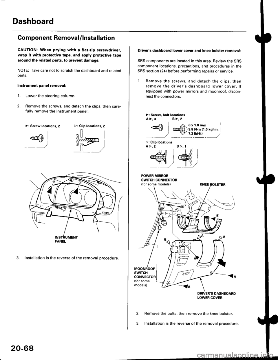
Dashboard
Component RemovaUlnstallation
CAUTION: When prying with a flat-tip screwdriver,
wrap it with protoctivo tape, and apply protective tape
around tho r6lat6d parts, to prevent damag6.
NOTE: Take care not to scratch the dashboard and relatedpans.
Instrument Danel removal:
1.Lower the steering column.
Remove the screws, and detach the clips, then care-
fully remove the instrument panel.
3. Installation is the reverse of the removal procedure.
>: Clip locations, 2
.il |
Pit)_ _ ,/
>: Screw locations,2
^l
@sl
:)
PANEL
20-68
Driver's dashboard lower cover and knee bolster removal:
SRS components are located in this area. Review the SRS
component locations, precautions. and procedures in the
SRS section (24) before performing repairs or service.
'1. Remove the screws, and detach the clips, then
remove the driver's dashboard lower cover. lf
equipped with power mirrors and moonroof, discon-
nect the connectors.
>: Screw, boh loc.tionsA>.3B>,2
_-rri I /a_6x1.0mm*\Y @{[) s 8 N'm tt o rst'm,
_-_- J _ \J- 7 2_rbtftl -_
>: Clip locationsA>.2 B >, 1
tu
DRIVER'S DASHBOARDLOWER COVER
Remove the bolts, then remove the knee bolster.
Installation is the reverse of the removal procedure.
Page 1299 of 2189
Glove box removal:
Remove the bolts, then remove the glove box.
>: Bolt locations,2
Installation is the reverse of the removal proceoure
Side air vent/Side defogger trim removal:
SIOE DEFOGGER TRIMSHOPTOWET_Carefully PrY rt at the
then remove it,side edge,
SIDE AIR VENTRemove the driver's dashboard lower
cover, or oPen the glove Dox,
HOOKS
then push the cliPs from each
opening by hand, and Pull it
out. Disconnect the connedors(driver's side).
HOOKS
DASH LIGHTSBRIGHTNESSCONTROLLERCONNECTOR{for some models)
CFUISE CONTROLMASTER SWITCHCONNECTOR(for some models)
Center dashboard lower covel:
1. Remove:
. Driver's dashboard lower cover
. Glove box
2. Remove the screws and bolt, then remove the cen-
ter dashboard lower cover. Disconnect the accesso-
ry socket connector'
>i Boh, screw locations
a>, 1 B>'5
A s*o.e-- I A
@;*;ry'-1'-.J _e)
3. Installation is the reverse of the removal proceoure'
(cont'd)
20-69
LOWER COVER