Page 980 of 2189

ATF Filter
l.Removal/lnstallation
!@ Make sure lifts, lEcks, snd safoty stands
ara pl8ced properly {sae section 1).
CAUTION: While removing and installing the ATF tilier,
be sure not to allow dust or other for6ign particle3 to
enter thg transmission.
1. Raise the front of the vehicle, and support it with
safety stands (see section 1).
2. Set the parking brake, and block both rear wheels
securely.
3. Remove the drain plug, and drain the CVT fluid.
Reinstall the drain plug with a new sealing washer
{see page 14-299).
fl,
5.
CAUTION: Keep all toreign particles out ot the
transmission.
Remove the ATF cooler hoses at the ATF cooler
lines. Turn the ends of the ATF cooler hoses up to
prevent ATF from flowing out, then plug the ATF
cooler noses.
CAUTION: Keep all foreign particles out of the
transmission.
Remove the right front mounvbracket.
10 x 1.25 mm4{ N.m {i1.5 kgf.m,33 lbf ft)
ATF COOLER LINE
10 x 1.25 mm54 N.m {5.5 kgt'm,
40 rbl.ft)
ATF COOLER HOSE(|'t
14-303
6. Remove the ATF cooler outlet line.
7. Remove the ATF cooler line bracket bolt.
8. Remove the ATF pan (fourteen bolts)
9. Remove the ATF cooler inlet line from the ATF pan
(three bolts).
10. Remove the ATF filter, and clean it.
11. Check that the ATF filter is in good condition.
12. Replace the ATF filter if it is clogged.
LINE BOLT28 N.m {2.9 kgf.m,21 lbt.ft)
ATF COO1TR OUTIET
6x1.0mm
ATF COOLER INI-ETLINE ERACKET BOLT8 x 1.25 mm26 N.m (2.7 kgt.m,20 rbtftt
O.RINGReplace.
ATF
ATF FILTER
ATF PAN
6x1.0mm12 N.m (1.2 kgt'm,8.7 lbl'ft)
lnstall the ATF filter in the reverse order of the
removal procedure.
GAUTION: Keep all foreign particles out ot the
transmission,
NOTE:
Replace the O-rings, the ATF pan gasket and
sealing washers.
lf the ATF cooler inlet line bracket is bent or
warped. put it back to the original position
GASKETReplace.
'13.
12 N m (1.2 kgf m,
Page 986 of 2189
O ATF DIPSTICK
O o-RING Replace.
.' SOLENOID HARNESS CONNECTOR
@ LOWER VALVE BODY ASSEMBLY
O DOWEL PIN
O LINE BOLT
.i ATTf COOUR IruIET LINE B8ACKET BOLT
€] lrr cooua truler LINE ASSEMBLY
O SEALING WASHER RePIACE'
G, ATF COOLER OUTLET PIPE
6) o-RING Replace.
@ ATF FILTER
fO o-RING Replace.
@ ATF PAN(3 DOWEL PIN(D O-RING Replace.
E) ATF STRAINER
@ ATF MAGNET(9 ATF PAN GASKET RePIACE'
O ATF MAGNET
€t oRAIN PLUG
@ SEALING wAStlER Replace.
TOROUE SPECIFICATIONS
Bolt/Nut No.Torque ValueSizeRemarks
8F
12J
18D
12 N.m {1.2 kgf m, 8.7 lbf'ft}
26 N.m (2.7 kgim,20 lbf'ft)
28 N.m (2.9 kgf'm,21 lbf'ft)
49 N.m (5.0 kgf'm, 36 lbf'ft)
6x1.0mm
8 x 1.25 mm
12 x 1.25 mm
18 x 1.5 mm
Line bolt
Drain plug
14-309
Page 991 of 2189
Transmission Housing/Lower Valve Body Assembty
Removal
NOTE:
. Clean all parts thoroughly in solvent or carburetor cleaner, and dry with compressed air.. Blow out all passages.
. When removing the lower valve body, replace the followingl- O-rings- ATF pan gasket- Sealing washers
DOWEL PIN
ATF STRAINER
6 x 1.0 mm BOLT
ATF PAN GASKETReplace.
ATF COOLER INLET LINEBRACKET BOLT8 x 1.25 mm
ATF COOI..ER INLET LINE
O.RINGReplace.
SOLENOIO HARNESS CONNECTOR
6 x'1.0 mm BOLT
LOWER VALVE BODY ASSEMBLY
6 x 1.0 mm BOLT
14-314
6 x 1.0 mm EOLT
Page 992 of 2189
l.
'1.
2.
5.
6.
7.
Remove the ATF cooler inlet iine bracket bolt'
Remove the ATF cooler outlet line
Remove the ATF pan (fourteen bolts).
Remove the ATF strainer {two bolts)
Remove the one bolt securing the solenoid harness
connector, then push the connector.
Remove the lower valve body (eight bolts)
Clean the inlet opening of the ATF strainer thoroughly
with compressed air, then check that it is in good
condition, and the inlet opening is not clogged'
ATF STRAINER
INLET OPENING
Replace the ATF strainer if it is clogged or damaged
NOTE: The ATF strainer can be reused it it is not
clogged.
2c'
c;2 ar\
14-315
Page 1006 of 2189
Differential
l.lllustrated Index
BOLTS10 x 1.0 mm98 N.m 110.0 kgf.m,72 tbl.ltlLeft-hand threads
FII{AL ORIVEN GEAR
BAIT EEANIM;
SET RING. 8() tnmSoloctivo pan
Bacl(lash Inspection
1. Place the differential assembly on V-blocks, and install
both axles.
2. Check the backlash of both pinion gears.
Standard (Newl: 0.05 - 0.15 mm 10.002 - 0.006 in)
PINION GEARS
lf the backlash is out of tolerance, replace the differ-
ential carrier.
14-329
Page 1011 of 2189

Transmission Housing Bearings
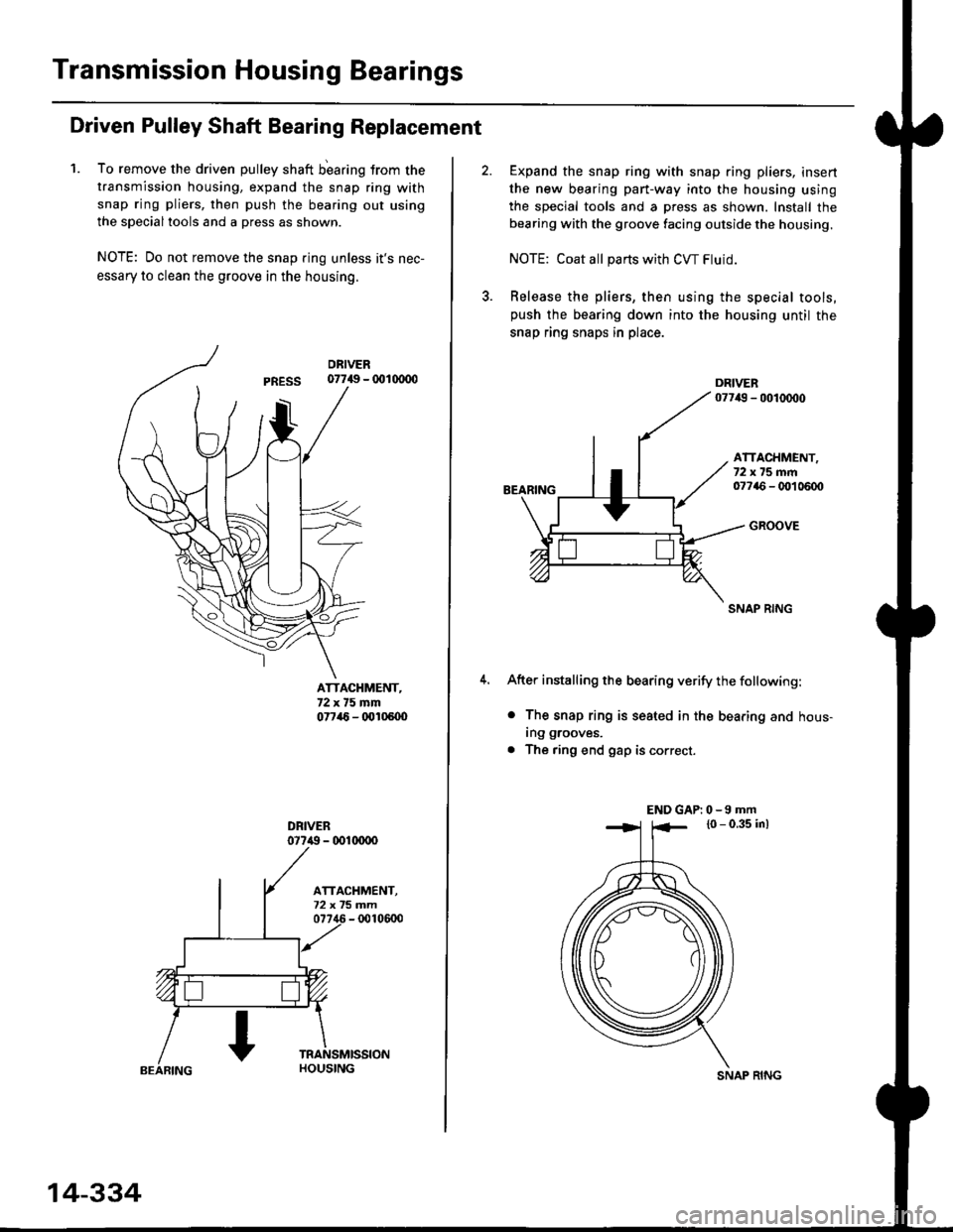
Driven Pulley Shaft Bearing Replacement
1. To remove the driven pulley shaft b'earing trom the
transmission housing, expand the snap ring with
snap ring pliers, then push the bearing out using
the specialtools and a press as shown.
NOTE: Do not remove the snap ring unless it's nec-
essary to clean the groove in the housing.
07749 - 001(xDo
ATTACHMENT,72x75mm07746 - (x'l05U)
077i() - 001(xrco
14-334
SNAP RING
Expand the snap ring with snap ring pliers, insert
the new bearing part-way into the housing using
the special tools and a press as shown. Install the
bearing with the groove facing outside the housing.
NOTE: Coat all pans with CW Fluid.
Release the pliers, then using the special tools,push the bearing down into the housing until the
snap ring snaps in place.
BEARING
ATTACHMENT,72x75mm07746 - OO1 0600
GROOVE
SNAP RING
After installing the bearing verify the following:
o The snap ring is seated in the bearing and hous-
ing grooves.
. The ring end gap is correct.
END GAP| 0 -9 mm
l0 - 0.35 inl
Page 1017 of 2189

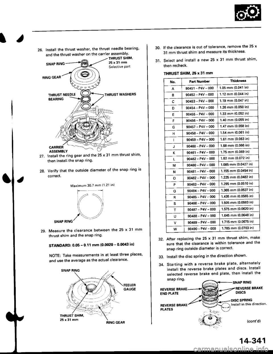
26. Install the thrust washer, the thrust needle bearing'
and the thrust washer on the carrier assembly'
SNAP RING
THRUST SHIM,
25x31 mm
Selective Pan
21.
24.
RING GEAR
THRUST NEEDLETHRUST WASHERS
EEARING
CARRIERASSEMBLY
lnstallthe ring gear and the 25 x 31 mm thrust shim,
then installthe snaP rrng.
Verify that the outside diameter of the snap ring is
correct,
Maximum 30.7 mm (1.21 in)
SNAP RING
Measure the clearance between the 25 x 31 mm
thrust shim and the snaP rlng.
STANDARD: O.O5 - 0.11 mm (0.0020 - 0.00'8 in)
NOTE: Take measurements in at least three places'
and use the average as the actual clearance
29.
,**r#*,".
'- t )
RING GEAR
14-341
30.
31.
lf the clearance is out of tolerance, remove the 25 x
31 mm thrust shim and measure its thickness'
Select and install a new 25 x 31 mm thrust shim.
then recheck.
THRUST SHIM, 25 x 31 mm
snap nng.RING
After replacing the 25 x 31 mm thrust shim, make
sure that the clearance is within tolerance and the
snap ring outside diameter is correct'
Install the disc spring in the direction shown'
Starting with a reverse brake plate, alternately
install the reverse brake plates and discs lnstall
selected reverse brake end plate, then install the
32.
33.
34.
REVERSEEND PLATE
BRAKE
Dtscs
SPRINGlnstall in this direction.
(cont'd)
REVERSEPI-ATES
No.Part Numb.lThickne*3
90451 - P4V - 0001.05 mm (0.041 in)
B90452-P4V-0001.12 mm (0.044 in)
c90453-P4V-000'1.19 mm (0.047 in)
D90454 - P4V - 000'l.26 mm (0.050 in)
90455-P4V-0001.33 mm (0.052 in)
F90456-P4V-0001.40 mm (0.055 in)
904s7-P4V-0001.47 mm (0.058 in)
90458-P4V-0001.54 mm (0.06'l in)
90459-P4V-000'1.61 mm (0.063 in)
J90460-P4V-0001.68 mm (0.066 inl
K90461-P4V-0001.75 mm (0.069 in)
90462-P4V-0001.82 mm (0.072 in)
M904a0-P4V-0001.085 mm (0.0427 in)
N90481-P4V-0001.155 mm (0.0454 in)
o901a2-P4V-0001.225 mm (0.0482 in)
90483-P4V-0001.295 mm (0.0510 in)
o90484-P4V-0001.365 mm (0.0537 in)
R904a5-P4V-0001.435 mm (0.0565 in)
90486-P4V-0001.5O5 mm (0,0593 in)
T90487-P4V-0001.575 mm (0.0620 in)
90488-P4V-00{)1.645 mm {0.0648 in)
90489-P4V-0001.715 mm (0.0675 in)
90490-P4V-0001.785 mm (0.0703 in)
Page 1018 of 2189

Transmission
Reassembly (cont'd)
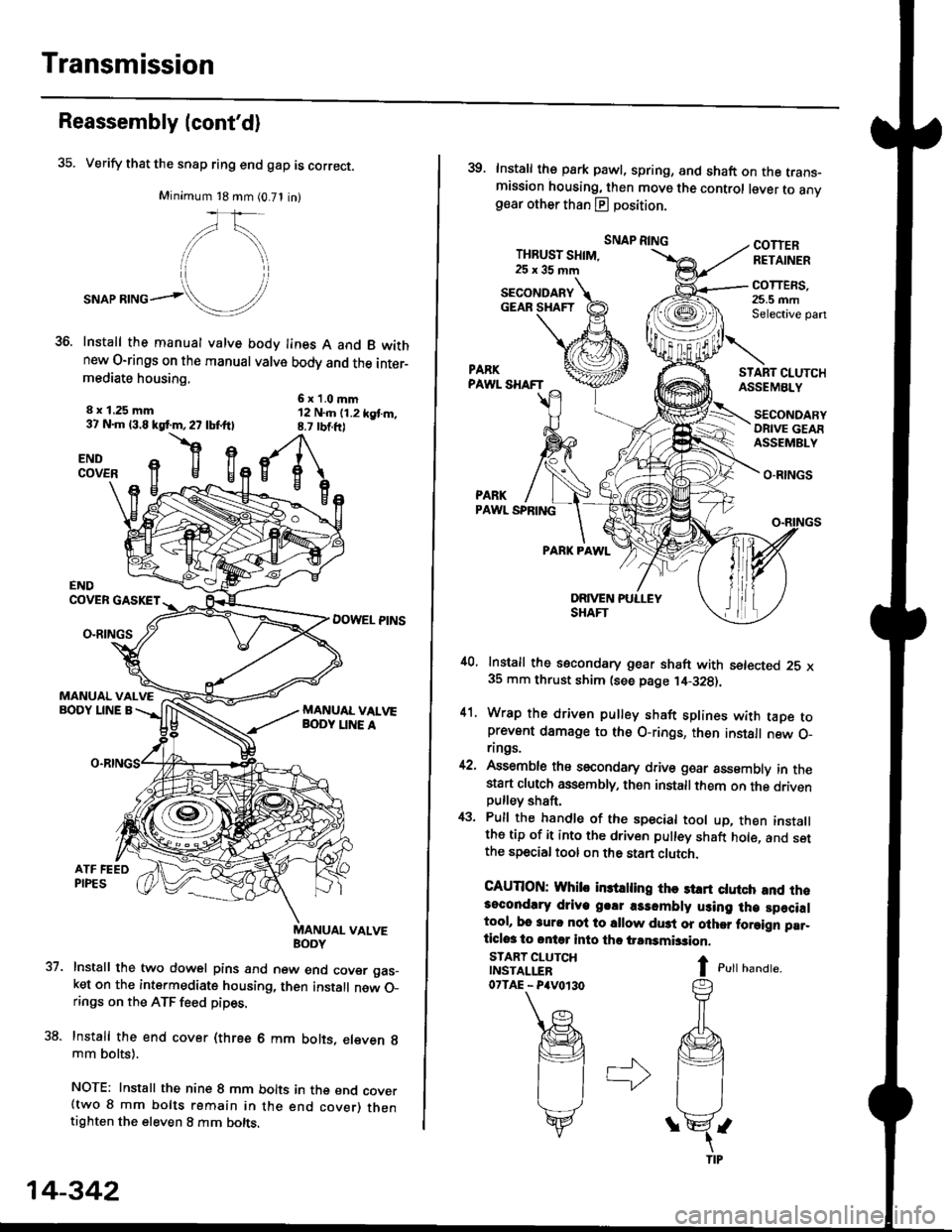
35. Verify that the snap ring end gap is correct.
Minimum 18 mm (0.71 in)
,/\,
."or**ol!/'
Install the manual valve body lines A and B wkhnew O-rings on the manual valve body and the inter-mediate housing.
6x1.0mm12 N..n (1.2 kgt m,8.7 rbtft)
8 x 1.25 mm37 N.m 13.8 kgf.m,27 lbf.ftl
flgENDCOVER
37.
ENDCOVER GASKET
DOWEL PINSO-RINGS
MANUAL VALVEBODY LINE A
uaNYuAL VALVE
Install the two dowel pins and new end cover gas_ket on the intermediate housing, then install new O_rings on the ATF feed pipes.
Install the end cover (three 6 mm bolts, eleven g
mm bolts).
NOTE: Install the nine 8 mm bolts in the end cover(two 8 mm bolts remain in the end cover) thentighten the eleven 8 mm bolts.
14-342
39. Install the park pawl, spring, and shaft on the trans-mission housing, then move the control lever to anvgear other than E position.
THBUST SHIM,25x35mm
SNAP RINGCOTTERRETAINER
COTTERS,25.5 mmSelective pan
START CI.UTCHASSEMBLY
O.RINGS
PARKPAWL SPRING
PARK PAWL
,10, Install the secondary gear shaft with setected 25 x35 mm thrust shim (see page ,14-328).
41. Wrap the driven pulley shaft splines with taDe toprevent damage to the O-rings, then install new O_rings.
42, Assemble ths secondary drive goar assembly in thestart clutch assembly, then installthem on the drivenpulley shaft,
43. Pull the handle of the special tool up, then installthe tip of it into the driven pulley shaft hole, and setthe special tool on the stan clutch.
CAUTION: Whib in3trling thc st rt ctutch and rh.3ocondlry driye g.!r a3sombly using lh€ specialtool, bo 3urc nol to sllow du3t or olher foraign par_ticlos to ontq into tho iransmbsion.
I c,rr r,unar".
SECONDARYGEAR SHAFT
START CLUTCHINSTALLER07TAE - P4V0r30
SECONDARYORIVE GEAFASSEMBLY