Page 911 of 2189
Troubleshooting Procedures
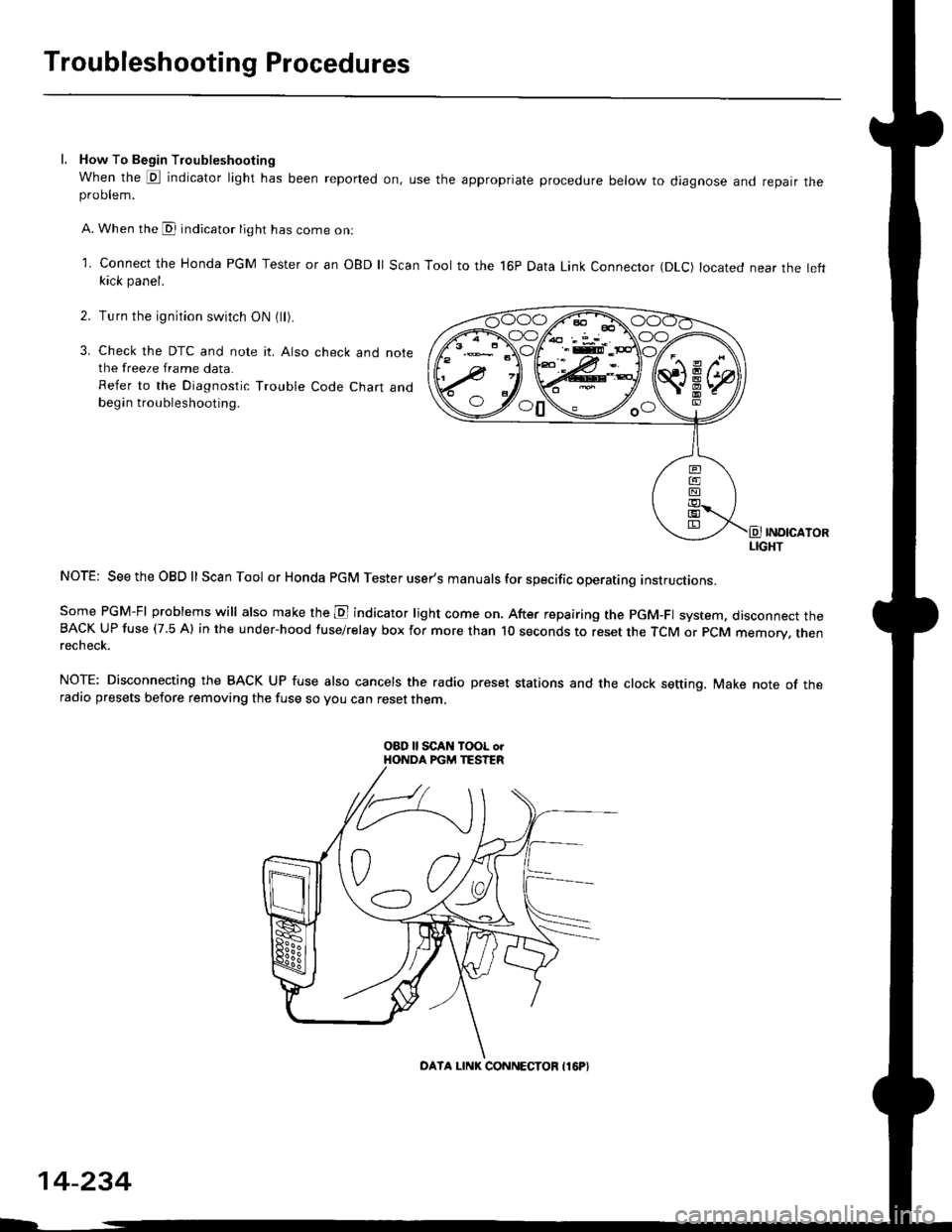
l. How To Begin Troubleshooting
When the E indicator light has been reported on, use the appropriate procedure below to diagnose and repatr theproDlem.
A. When the @ indicator light has come on:
l connect the Honda PGM Tester or an oBD ll Scan Tool to the 16P Data Link Connector (DLc) located near the leftkick panel.
Turn the ignition switch ON (ll).
Check the DTC and note it. Also check and notethe freeze frame data.
Refer to the Diagnostic Trouble Code Chart andbegin troubleshooting.
INOICATORLIGHT
NOTE: SeetheOBDll Scan Tool or Honda PGM Tester user's manuals for specific operating instructions.
Some PGM-FI problems will also make the E indicator light come on. After repairing the pGM-Fl system, disconnect theBACK UP fuse (7.5 Al in the under-hood fuse/relay box for more than l0 seconds to reset the TCM or PCM memory, rnenrecheck.
NOTE: Disconnecting the BACK UP fuse also cancels the radio preset stations and the clock setting. Make note of theradio presets before removing the fuse so you can reset them,
2.
3.
o0\e--loo
OATA LINK CONNECTOB I16P}
14-234
Page 913 of 2189
Troubleshooting Procedures
(cont'd)
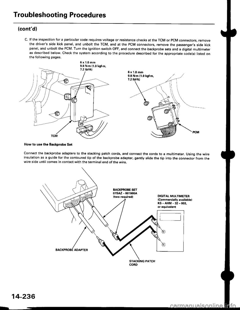
C. lf the inspection for a particular code requires voltage or resistance checks at the TCM or PCM connectors, removethe driver's side kick panel, and unbolt the TCM, and at the PCM connectors, remove the passenger's side kickpanel, and unbolt the PCM. Turn the ignition switch OFF, and connect the backprobe sets and a digital multimeteras described below. Check the system according to the procedure described for the appropriate code(s) listed onthe following pages.
6x1.0mm9.9 N.m {1.0 kgt m,
How to use lhe Backprob€ SE{
Connect the backprobe adapters to the stacking patch cords, and connect the cords to a multimeter, Using the wireinsulation as a guide for the contoured tip of the backprobe adapter, gently slide the tip into the connector from thewire side until comes in contact with the terminal end of the wire.
BACI(PROBE SET07saz - 001 txtoaItwo requirodlDIGITAL MULTIMETER(Commarcially avsibblelKS-AHM-32-(x)3,or oquivalent
6 x 'l,0 mm9.E N.m (1.0 kgf.m,7.2 rbtftt
coRo
14-236
ADAPTER
Page 953 of 2189

Electrical Troubleshooting ('gg - 00 Modelsl
Troubleshooting Flowchart - start clutch control Linear solenoid (cont,d)
Frcm page 14.275
SOLENOID HARNESS 8P CONNECTOR
T6rminal side of male terminals
Wire side of f6male terminals
SC LSM(PNK/BLU)
Measurs Start Clutch ControlLinear Solenoid R€aistance at thsSolenoid Harne€s Connector:1. Disconnect the solenoid har-ness 8P connector.2, M easu re the resistancebetween the No. 4 and No. Iterminals of the solenoid har-ness 8P connector,
ls the resistance 3.8- 6.8 0?
Check Start Clutch Control Line.rSolenoid tor a Short Circuit:Check for continuity between thobody ground and the 818 termi-nal and B2Sterminal individually.
R€p.ir short in th. wire bctw.onth6 818 and 825 termin.lr rndthe 3hift cont ol linc.r solonoid.
Measure Start Clutch ControlLinear Solenoid R6ist.nco:1. Connect the solenoid harness8P conn€clor.2. Measure the resistancebetlveen the 818 and 825 ter,mtnats,
Raprir looa. t€.minal or opan intha wirars lratwe.n the B18 and825 terminal3 and tha st!rtclutch control linoar 3olanoid,
ls the resistance 3.8-6.8 O?
Check to. loose tarminal fit in thoPCM connactors. It necessary,substitute a known-good PCMand recheck.
SC LSP
SC LSM
14-276
Page 955 of 2189
Electrical Troubleshooting ('99 - 00 Models)
Troubleshooting Flowchart - Inhibitor Solenoid (cont'dl
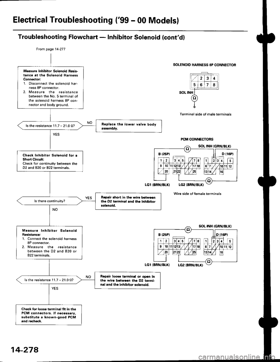
SOLENOID HARNESS 8P CONNECTOR
SOL INH
Terminal side of male terminals
Wire side oI temale terminals
Mersure Inhibitor Solenoid R6b-t.nce at the Solenoid Harne3sConn€ctor:1. Disconnect the solenoid har,ness 8P connector,2. Measure the resistancebetween the No.5 terminal ofthe solenoid harness 8P con-nector and body ground.
ls the resistance 11.7 - 21.0 O?
Check Inhibitor Solonoid fo. .Short Ci.c!it:Check for continuity between theD2 and 820 or 822 terminals.
R.p.ir 3hort in thc wire botwaanth€ 02 t.rminal and the inhibhotsolenoid.
Measur6 Inhibitor SolenoidRe3istance:1, Connect the solenoid harness8P connector.2, Measure the lesistancebetween the D2 and 820 or822 terminals.
Rcpair loo3. tarminal or opan intho wha brtw.€n tho D2 to.mi-nal .nd tho inhibitor lolonoid.
ls the resistance 11.7 - 21.0 O?
Check fol looso torminal fit in thePCM connectors. lf n€cessaay,substitute a known-good PCMand r€check.
Ftom page 14-277
LGl IBRN/BLKI
LGl{BRN/ALKI
B t25P) ll D t16P)
B t25Pt otl6Pt
14-274
Page 957 of 2189
Electrical Troubleshooting ('gg - 00 Models)
Troubleshooting Flowchart - Drive pulley Speed Sensor (cont,d)
PCM CONNECTOR D {16P}
Wire side of temale terminals
From page 14-279
Measure Drivo Pulley Speed Sen-sor Circuit tor an Open:1. Connect the drive pulleyspeed sensor connector,2. lvleasu re the resistancebetween the Dl1 and Dl2 ter-minals.
R6pair loose tgrminal or opan inthe wiros betwo€n tho D1,l .ndOl2 tarminrl! .nd th. drivs pul-ley speed *n3or.
ls the resistance 350 - 600 O?
Ch6ck for loose lerminal tit in thePCM connectors, ll nece3saay,substituto a known-good PCM6nd r€check.
14-280
Page 973 of 2189
Road Test
NOTE: Warm up the engine to normal operating temperature (the radiator fan com6s on).
1. Apply the parking brake and block the wheels. Start the engine, then shift to the E position while depressing the
brake pedal. Depress the accelerator pedal and release it suddenly. The engine should not stall.
2. Test in E position
Park the vehicle in a slope (approx. 16'). apply the parking brake, and shift into E position. Release the brake; the
vehicle should not move.
3. Test-drive the vehicle on a flat road in the position shown in the table. Check that the engine speeds meet the approx-imate vehicle speeds shown in the table.
NOTE: Throttle position sensor voltage represents the throttle opening. To monitor the throttle position sensor volt-age, use one of the following methods:
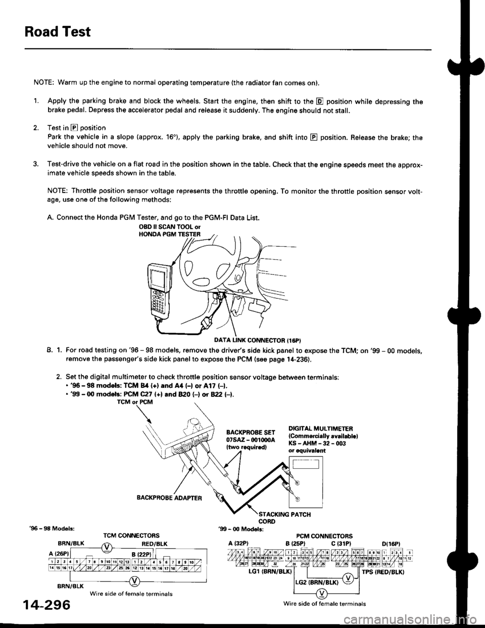
A. Connect the Honda PGM Tester, and go to the PGM-FI Data List.
A1For road testing on '96 - 98 models, remove the drive/s side kick panel to expose the TCM; on '99 - OO models,remove the passenger's side kick panel to expose the PCM (see page l,[-236),
Set the digital multimeter to check throttle position sensor voltage between terminals:. '96 - 98 modols: TCM 84 {+} and Aa (-) or A17 (-1.. '99 - 0O models: FCM C27 {+l and 820 (-l ot 822 l-1.
DIGITAL MULTIMETER(Commerci.lly rvrilabl.lKS-AHM-32-003or oquivalant
BACKPROBE ADAPTER
BRN/BLK
A {26P1
TPS {BED/BLK}
'96 - 98 Models:
BRN/BLK
14-296
OBD ll SCAN TOOL orHONOA PGM TESTER
D{16Pt
Ware side ot female terminals
Wire side of female terminals
Page 977 of 2189
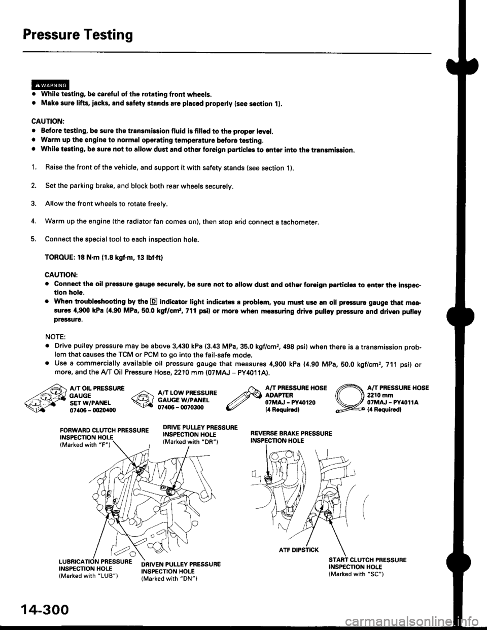
Pressure Testing
. While testing, be careful of the rot8ling front wheels.
. M8k6 suro lifts, iacks, and satety stands are placed properly lsee section 11.
CAUTION:
. Before testing, be sur. the transmb3ion fluid is fillod to the propor lcvel.. Warm up the engin€ to nolmal operating tsmperature bofore testing. While t€sting, be 3ure not to allow dust and other loreign particles to onler into the transmi$ion.
1. Raise the front of the vehicle, and support it with safety stands (see section 1).
2. Set the parking brake. and block both rear wheels securely.
3. Allow the front wheels to rotate freely.
4. Warm up the engine (the radiator fan comes on), then stop arid connect a tachometer.
5. Connect the special tool to each inspection hole.
TOROUE: 18 N.m (1.8 kgt'm, 13 tbtfr)
GAUTION:
. Connect the oil pressuro gauge !!€curoly, bs sur6 not to allow dust and other foroign particlG3 to ontar the inspsc-tion hole.
. Whon troubleshooting by tho E indicltor light indic.t6 a problam. you mu3t u3e an oil p.essure gluge that moa,sures 4,9(X) kPa (a.90 MPa,50.0 kS cr*,771psi) or more when molsuring driv. pulley pressure and driven pullcypre33ure.
NOTE:
. D.ive pulley pressure may be above 3,430 kPa (3.i8 MPa,35.0 kgf/cmr, 498 psi) wh€n there is a transmission prob-
lem that causes the TCM or PCM to go into the fail-safe mode,. Use a commercially available oil pressure gauge that measures 4,900 kPa {4.90 MPa, 5O.O kgf/cmr, 711 psi) ormore, and the Ay'T Oil Pressure Hose, 2210 mm (07MAJ - PY4011A).
FORWARD CLUTCH PRESSUREINSPECTION
lMarked with "F")
REVERSE BRAKE PRESSUREINSPECTION I.IOLE
A/T OIL PRESSUREGAUGESET W/PANEL0ta{r6 - oO2Oi|(Xt
A/T LOW PRESSUREGAUGE W/PANEL0706 - qt7o:t{ro
DRIVE PULLEY PRESSUREINSPECTION HOI.E(Marked with "DR")
A/T PRESSURE HOSEADAPTER07MAJ - PYar'120lil R.qulr.d)
A/T PRESSUBE HOSE2210 mm07MAJ - PYitollAla R.quir.d)
(
INSPECNON HOLE(Marked with "SC")
CLUICH PRESSURE
INSPECTION HOLE(Marked with "LUB")
DRIVEN PULLEY PRESSUREINSPECTION HOLElMarked with "DN")
14-300
ATF DIPSTICK
Page 979 of 2189

Lower Valve Body Assembly
Replacement
@ Make sure lifts, iacks, and saf€ty stands
are placsd prop€rly {sea section 1).
CAUTION: While removing and installing th6 lower
valve body asssmbly, b€ sule not to allow dust and
other for€ign particles to entsr inio the transmksion.
1. Raise the front of the vehicle, and support it with
safetv stands (see section 1).
2. Set the parking brake, and block both rear wheels
securetv.
4.
6.
Remove the drain plug, and drain the CVT fluid.
Reinstall the drain plug with a new sealing washer(see page 1+299).
CAUTION: Keop all of other toreign parliclos out of
the transmission.
Disconnect the 8P connector from the solenoid har-
ness connector.
Remove the ATF cooler hoses at the ATF cooler
lines. Turn the ends of the ATF cooler hoses up to
prevent ATF from flowing out, then plug the ATF
cooler noses.
CAUTION: Keep all of other foroign particlo3 out of
tho transmission.
Remove the right front mounvbracket.
10 x 1.25 mmila N.m (,1.5 kgf.m, 33 lbtft)
RIGHT FRONTMOUNT/BRACKET
ATF COOLER LINE
10 x 1.25 mmsil N.m 15.5 kgf.m,40 rbr.ft)
ATF COOLER HOSE
14-302
14.
7. Remove the ATF cooler outlet line.
8. Remove the ATF cooler line bracket bolt.
9. Remove the ATF pan (fourteen bolts).
10. Remove the ATF strainer (two bolts).
1 l. Remove the one bolt securing the solenoid harness
connector,
12. Remove the
bolts).
lower valve body assembly (eight
LINE BOLT28 N.m (2.9 kgtm,21 lbtft)SEALINGReplace.
ATF COOI.-EROUTLET
OOWEL PIN
O.RINGFeplace.
SOLENOIO HARNESSCONNECTOR
5x1.0mm12 N.m 11.2 kgt.m,8.7 tbt.ftlO.RINGReplace.ATFSTNAINER
6x1.0mm12 N.m 11.2 kgt m,E.7 tbt'ft)
OOWEL NN
BODY ASSEMBLY
6x1.0mm12 N.m 11.2 kgf.m,8.7 rbf.ft)
ATF PAN GASKETReplace.
VALVE
ATF COOLER INLETUNE BRACKET BOLT8 x 1,25 mm26 N.m {2.7 kgf.m,20 tbf.frl
13.
ATF PANx 1.0 mm12 N.m 11.2 kgf.m, E.7 lbf.ftl
Install the new lower valve bodv in the reverse
ordgr of the removal orocedure.
CAUTION: Koep all ot other fo.oign particles out of
ths transmission.
NOTE:
. Replace the following parts:
- O-rings on the solenoid harness connector
and the ATF strainer- ATF pan gasket- Sealing washers
. lf the ATF cooler inlet line bracket is bent or
warped, put it back to the original position.
Perform the start clutch calibration orocedure on
page 14-293.