Page 770 of 2189

Electrical Troubleshoot:ng ('gg - 00 Models)
Troubleshooting Flowchart - Shift Control Solenoid Valve B (cont,dl
PCM CONNECTOR A {25PI
LGl (BRN/BLK)
IBRN/BLKI LG2IBRN/BLK)
Wire side of temale terminals
Wire sid€ ot female terminals
FCM CONNECTORS
SHIFT @NTROL SOENOID VALVEA/A ASSEMBLY CONNECTOR (2PI
.-_
1)2-.T-
I sn e tcanlwxrt
(o
YI
Terminal side oI male terminals
Check for continuity between the820 terminal and body ground,and between the 822 terminaland body ground.
Ropair opan in the wirgsb.twocn the 820 rnd 822 te.mi,n.ls and ground lG10t), and..p.ir poor ground lG10t).
Check Shift Control Sol.noidVrlve B tor a Short Ci.cuit:1. Disconnect the 2P connectorfrom the shift control solenoidvalve A/B assembly.2. Check for continuity betweenthe D2 and 820 or 822 termi-nals.
Repair 3hort to ground in tho wirebotw.en tha 02 torminsl and theshift com.ol rolonoid v.lv. B.
Meaiuro Shift Cont.ol SolonoidVrlve B Raailtrnca at the SolonoidConn€c,toa:Messure the r€sistance belweenthe No. 2 terminal of the 6hiftcontrol solenoid valve A/Bassembly connector and bodyground.
R.pl.co th. 3hift control lolenoidv!lv. A/8.lsombly.ls the resistance 12 - 25 O?
Chack for open in the wi.ebetwoon th€ D2 termin.l and the3hift control lolanoid valv6 8.
B (25P1 - llDt
From page'14-91
SH B (GRN/WHTI
\
14-92
Page 772 of 2189
Electrical Troubleshooting ('gg - 00 Modelsl
From page 14-93
Measure CounteJahaft SpeedSensor Circuit tor an Open:1. Connect the countershaltspeed sensor connector,2. Measure the resistancebetween the Dl0 and D16 termtnats.
Roptir loo.€ t6.minal or opan inth6 wir€! betwo€n lho D10 lndD16 t.rmina13 and the count.r-shatt apaad aaNor.
ls the resistance 400 - 600 O?
Check for loose t.rminal frt in thePCM connectors. It necalsary,3ubstitute a known-good PCMand recheck.
Troubleshooting Flowchart - Countershaft Speed Sensor (cont,d)
PCM CONNECTOR D I16PI
Wire side of female terminals
\
14-94
Page 775 of 2189

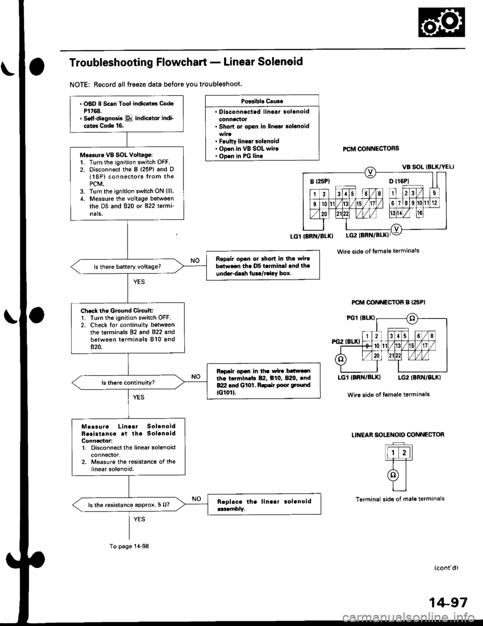
Troubleshooting Flowchart - Linear Solenoid
NOTE: Record all freeze data before you troubleshoot.
Poitibl. Cau3.
. Disconnacted linoaJ tolanoidconnaclol. Shorl or opon in linolr solonoid
. Flulty linoar 3olenoid. ODon in VB SOL wit.. ODen in PG linoPCftI @NNECTORS
Wire side ol female terminals
PCM OONNECTOR B I25PI
LGT (BNN/BLKI LG2 {BBN/BLKI
Wir6 side of Iemale terminals
LINEAF SOITNOID OONNECTOR
Flr-11=T=T
olYI
L_l
Terminal side of mal€ termanals
(cont'd)
B t25Pl D {16P1
. OBD ll Scln Tool indic.t.t CodoP1768.. Self-diagnosis E indicltol indi-
cat6 Cods 16.
Moasur. VB SOL Voltago:1. Turn the ignition switch OFF.2. Disconnect the B {25P) and D(16P) connectors from thePCM.3. Turn the ignition switch ON (lll.
4. Measure the voltage between
the D5 and 820 or 822 termi-
nals.
Ropair opan or thort in dla wi.9hrw..n th. D5 t.rminrl .nd th.
und.r-d.rh fu ta/r.l.y box.
Ch.ck th. Ground Circuit:1. Turn the ignition switch OFF.2. Check lor continuity betwoenthe terminals 82 and 822 and
between terminals 810 and820.
Rapair opal| in tfr wi|! batlwaoth. tcrrnln.l. 82, B10, B:20. .ndBZI .id Gt01. R.p.ir poor ground
tG10rl.
M.!sure Linea. SolenoidRcai3tancc rt tha SolanoidConn6ctor:1. Disconnect the linearsolenoidconnectol,2. Measure the resistance of thelinear solenoid.
ls the resistance approx. 5 O?
To page 14-98
1+97
Page 797 of 2189

Pressure Testing
@I While testing, be caroful of th€ rotating front wheels.
. Make sure lifts, iacks, and satoty stands are placod properly (see section 1)'
CAUTION:
. Beforo iesting, be sure the transmission fluid is tilled to tho proper level'
. Warm up tho engine before testing'
1. Raise the vehicle (see section 1).
2. Warm up the engine, then stop the engine and connect a tachometer'
3. Connect the oil pressure gauges to each inspection hole.
TOROUE: 18 N.m (1.8 kgf'm, 13 lbnft)
cAUTloN: connact the oil pressuro gauges securely; be suro not to allow dust and other foreign Parlicles to entel
the inspestion holos'
A/T OIL PRESSURE GAUGESET w/PANEL07t06 - 0020400
A/T LOW PRESSURE GAUGE
SET WPANEL07406 - 0070300
A/T OIL PRESSURE HOSEADAPTER07Mru - PY0120(4 requiJedl
A/T OIL PBESSURE HOSE
2210 mmOTMAJ - PY4{)llA
14 roquircdl
Start the engine, and measure the respective ptessure as follows'
a Line Pressure
. 1st Clutch Pressure
. 2nd,3rd and 4th Clutch Pressure
Install a new washer and the sealing bolt in the inspection hole. and tighten to the specified torque'
TOROUE: l8 N.m (1.8 kgf'm,13lbf'ft)
NOTE: Do not reuse old sealing washers; always replace washers'
(cont'd)
14-119
Page 820 of 2189
Main Valve Body
Disassembly/lnspection/Reassembly
NOTE:
. Cleanall parts thoroughly in solvent or carburetor cleaner, and drywith compressed air. Blowoutall passages.. Replace the valve body as an assembly if any pans are worn or damaged.. Check all valves for free movement. lf anyfail toslidefreely, see Valve Body Repairon page,l4-139.. Coat all parts with ATF during assembly.
CAUTION: Do not use a magnet to removs tha check balls; it may magnetizo the balls.
CPB VALVEVALVE CAP CLIP
ORIFICE CONTROL VALVE
BALLS, 8
lST ACCUMULATOR CHOKE
MODULATORVALVE
RELIEF VALVEVALVE
MAIN VALVE EODYInspect for wear, scratchesand scoring.
SEBVO CONTROL VAL
I.2 SHIFT VALVE
14-142
VALVE CAP
Page 825 of 2189
Lock-up Valve BodY
Disassembly/lnspection/Reassembly
NOTE:
. Clean all pans thoroughly in solvent or carburetor cleaner' and dry with compressed air' Blow out all passages'
a Replace the valve body as an assembly if any parts are worn or d€maged'
. Checkall valves for free movement ttanytaitio stlae freely' see Valve Body Repairon page 14-'139'
. Coat all parts with ATF during assembly
LOCK.UP VALVE BODY
Inspect for wear, scratchesand sconng.
VALVE CAP
LOCK-UP TIMING VAL
SPRING SPECIFICATIONSUnit: mm (in)
73.1 t2.902J
ao.7 13.'17717.6 (0.302)
8.1 (0.319)Lock-up shift valve sPrang
Lock-up timing valve sPrlng
14-147
Page 852 of 2189

Transmission Housing Bearings
L
Mainshaft/Countershaft Bearings Replacement
To remove the mainshaft and countershaft bearings
from the transmission housing, expand each snap
ring with snap ring pliers, then push the bearing out
using the special tools and a press as shown.
NOTE: Do not remove the snap rings unless it's
necessary to clean the grooves in the housing.
DRIVER07749 - 0010000
ATTACHMENT,62x68mm
PRESS
\
07746 -
DFIVEB07749 - 0010000
TTACHMENT
ATTACHMENT
. Mainshaft Bearing Installation us€:
ATTACHMENT. 72 x 75 mm
07746 - 0010600. Countershaft Bearing Installation use:
ATTACHMENT, 62 x 68 mm
077/16 - 0010500
IRN{L{r.)n
\bZ
MAINSHAFT BEARING
L
14-174
SNAP RING
Expand each snap ring with snap ring pliers, insert
the new bearing part-way into the housing using
the special tools and a press as shown, Install thebearing with the groove facing outside the housing.
NOTE: Coat all parts with ATF.
Release the pliers, then push the bearing down intothe housing until the ring snaps in place around it.
07749 - 0010000
ATTACHMENT
. Mainshaft Bearing Removal use:
ATTACHMENT, 72 x 75 mm
077/16 - 0010600. Counte6haft Bsaring Removal use:
ATTACHMENT, 62 x 68 mm
07746 - 0010500
After installing the bearing verify the following:
. The snap ring is seated in the bearing and hous-
ing grooves.
. The ring end gap is correct.
(0 - 0.28 in)ENDGAP:0-7mm
Page 868 of 2189

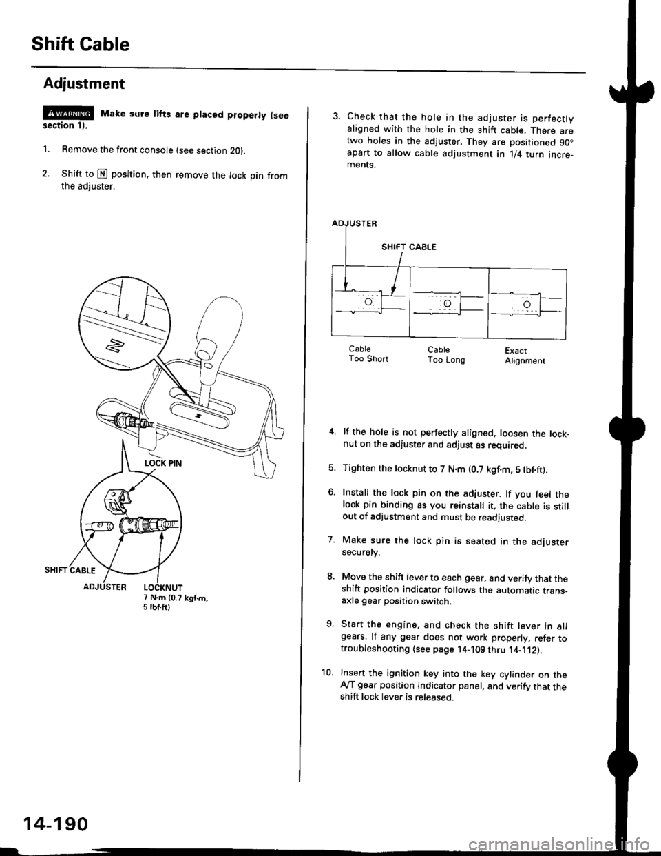
Shift Cable
Adjustment
@ Make sure lifts are ptaced properly (see
section 1).
1. Remove the front console (see section Z0l.
2. Shift to @ position. then remove the lock pin fromthe adiuster.
7 N.m (0.75 tbtftlkgtm.
14-190
3. Check that the hole in the adjuster is perfectlyaligned with the hole in the shift cable. There aretwo holes in the adjuster. They are positioned 90.apart to allow cable adjustment in 1/4 turn incre-ments.
ExactAlignment
4. lf the hole is not perfectly aligned, loosen the lock-nut on the adjuster and adjust as required.
5. Tighten the tocknut to 7 N.m (0.7 kgf.m, 5 tbf.ft).
6. Install the lock pin on the adjuster. lf you feel thelock pin binding as you reinstall it, the cable is stillout of adjustment and must be readjusted.
7. Make sure the lock pin is seated in the adjustersecuretv.
8. Move the shift lever to each gear, and verify that theshift position indicator follows the automatic trans-axle gear position switch.
9. Start the engine, and check the shift lever in allgears. lf any gear does not work properly, refer totroubleshooting (see page 14-109 thru 1'4-'112).
10. Insert the ignition key into the key cylinder on theAy'T gear position indicator panel, and verify that theshift lock lever is released.
CableToo ShortCableToo Long