Page 1058 of 2189

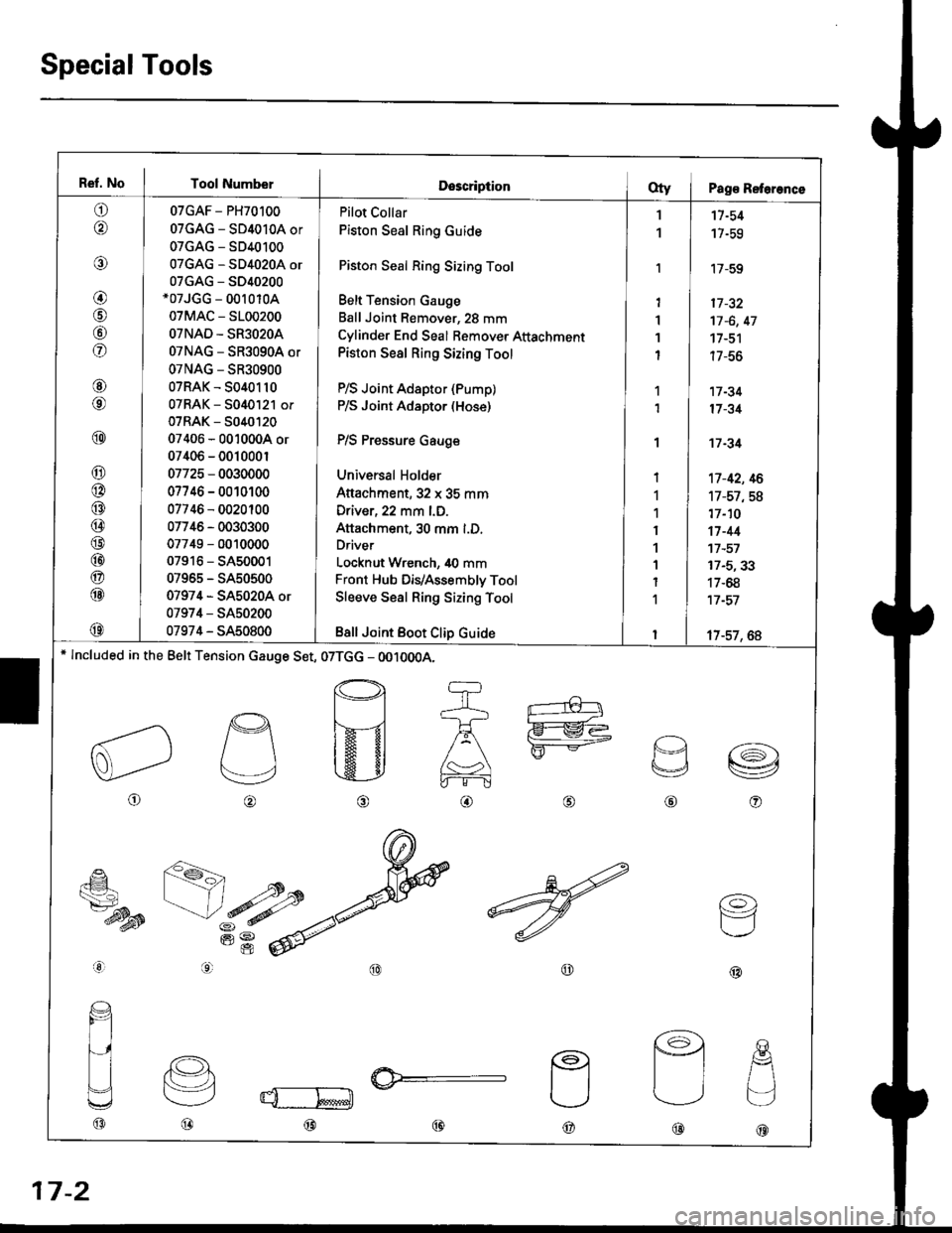
Ref. No I Tool NumberDescriptionOty I Pag€ Reterence
o
@
@
@
@
fof
@
@
@
@
@
@
@
@
@
@
@
@
@
07GAF - PH70100
07GAG - SD4010A or
07GAG - SD40100
07GAG - SD4020A or
07GAG - S040200*07JGG - 00r 010A
07MAC - 5100200
OTNAD - SR3O2OA
07NAG - SR3090A or
07NAG - SR30900
07RAK - 5040110
07RAK - 5040121 or
07RAK - 5040t20
07406 - 0010004 or
07406 - 001000r
07725 - 0030000
07746 - 0010100
07746 - 0020100
07746 - 0030300
07749 - 0010000
07916 - SA50001
07965 - SA50500
07974 - SA5020A or
07974 - SA50200
07974 - SA50800
Pilot Collar
Piston Seal Ring Guide
Piston Seal Ring Sizing Tool
Belt Tension Gauge
Ball Joint Remover, 28 mm
Cylinder End Seal Bemover Attachment
Piston Seal Ring Sizing Tool
P/S Joint Adaptor (Pump)
P/S Joint Adaptor (Hose)
P/S Pressure Gauge
Universal Holder
Attachment,32 x 35 mm
Driver, 22 mm l.D.
Attachment, 30 mm l.D.
Driver
Locknut Wrench, 40 mm
Front Hub DiVAssembly Tool
Sleeve Seal Ring Sizing Tool
Bsll Joint Boot Clip Guide
1
1
'I
1'I
1
I
1
1
I
1
1
I
1
1
I
1
I
11-54
17-59
'17-59
17 -32
17 -6, 47
17-51
| /-ao
17 -34
17 -31
't7 -34
't7-42, 16
17-57,58
17-10
17-44't7 -57
17-5,33
17-68
17 -57
17-57, 6A* lncluded in the Belt Tension cauge Set, 07TGG - OO10OOA.
o
p
v
@o
€_
ts7-dysB
aal
@@
(o)
F=1
@@@
@@@
17-2
Page 1072 of 2189
System Description
Fluid Flow Diagram
The system is a compact rotary-valve-type power steering, connected to the steering gearbox. The fluid pressure is pro-
vided by a vane-type pump which is driven by the engine crank pulley. The amount of fluid and pressure is regulated by
the flow control valve built into the pump. The fluid pressure from the pump is delivered to the valve body unit around the
pinion of the steering gearbox. The valve inside the valve body unit controls the hydraulic pressure and changes the direc-
tion of the flow. The fluid then flows to the power cylinder. where rack thrust is generated. Fluid returning from the power
cylinder flows back to the reservoir, where the fluid is "filtered" and supplied to the pump again.
RESERVOIR
VALVE BOOY UNIT
SUB.VALVE
FLOW CONTROL VALVESTEERING GEARBOX
17-16
Page 1074 of 2189

System Description
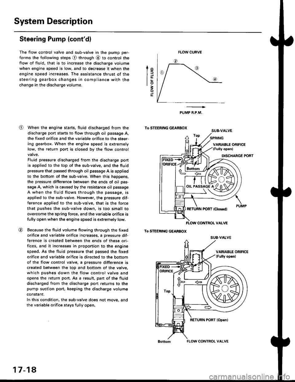
Steering Pump (cont'dl
The flow control valve and sub-valve in the pump per-
forms the following steps @ through @ to control the
flow of fluid, that is to increase the discharge volume
when engine speed is low, and to decrease it when the
engine speed increases. The assistance thrust of the
steering gearbox changes in compliance with the
change in the discharge volume.
When the engine starts, fluid discharged from the
discharge port starts to flow through oil passage A,
the fixed orifice and the variable orifice to the steer-
ing gearbox. When the engine speed is extremely
low, the return port is closed by the flow control
Fluid pressure discharged from the discharge port
is applied to the top of the sub-valve, and the fluid
pressure that passed through oil passage A is applied
to the bottom of the sub-valve. When this happens,
the pressure difference between the ends of oil pas-
sage A, which is caused by the resistance oil passage
A when the fluid flows through the passage. is
applied to the sub-valve, However, the pressure dif-
ference applied to the sub-valve. that is the force
that pushes the sub-valve down, is too small to
overcome the spring force, and the variable orifice is
fully open when the engine speed is extremely low.
Because the fluid volume flowing through the fixed
orifice and variable orifice increases, a pressure dif-
terence is created between the ends of these ori-
fices, and it increases in proportion to the engine
speed. As the fluid pressure that passed the fixed
orifice and variable orifice is directed to the bottom
of the flow control valve. a pressure difference is
created between the top and bottom of the valve,
which pushes down the flow control valve and
opens the return port. As a result, pan of the fluid
discharged from the discharge port feturns to the
pump suction port, keeping the discharge volume
constant.
In this condition, the sub-valve does not move. and
the variable orifice stays fully open.
lo
trrtrrlo3
J
o
PUMP R.P.M.
To STEERING GEARBOXSUB.VALVE
To STEEnING GEARBOX
FLOW CURVE
!rs+/f/ffih\
o,,-i^"l^tKzYt)91y ul3Yl
FLOW CONTNOL VALVE
su8-vALvE
ORIFICE
ToP
17-18
FLOW CONTROL VALVE
Page 1076 of 2189

System Description
Steering Gearbox
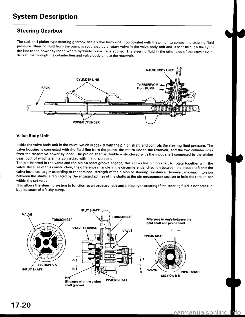
The rack-and-pinion type steering gearbox has a valve body unit incorporated with the pinion to control the steering fluidpressure. Steering fluid from the pump is regulated by a rotary valve in the valve body unit and is sent through the cylin,der line to the power cylinder, where hydraulic pressure is applied. The steering fluid in the other side of the power cylin,der returns through the cylinder line and valve body unit to the reservoii.
VALVE EODY UNIT
CYLINDER LINE
To RESERVOm +-From PUMP -;
POWER CYLINDER
Valve Body Unit
Inside the valve body unit is the valve, which is coaxial with the pinion shaft, and controls the steering fluid pressure. Thevalve housing is connected with the fluid line from the pump, the return line to the reservoir, and the two cylinder linesfrom the respective power cylinder. The pinion shaft is double - structured with the input shaft connected to the piniongear, both of which are interconnected with the torsion bar.
The pin inserted in the valve and the pinion shaft groove engage; this allows the pinion shaft to rotate together with thevalve. Because of this construction, the difference in angle in the circumferential direction between the input shaft and thevalve becomes larger according to the torsional strength of the pinion or steering resistance. However, maximum torsionbetween the shafts is regulated by the engaged splines of the shafts at the pin engagement section to hold the torsion barwithin the set value,
This allows the steering system to function as an ordinary rack-and-pinion type steering if the steering fluid is not pressur-
ized because of a faulty pump,
VALVE
Difforence in angle botwoon theinput shaft and pinion shsft
PINION SHAFT
lo
INPUT SHAFT
-l
a
17-20
INPUT SHAFT
Page 1126 of 2189
Special Tools
Ref. No. Tool NumborDescriptionOty Page Reteronc€
o
€)
@
\9
o
@aa\
@
o
@
@
@
07GAF - SE00200
07GAF - SE00401
07GAG - SD40700
07JAF - SH201 l0
07JAF - SH20120
07JAF - SH20200
07MAC - S100200
07746 - 0010500
07749 - 0010000
07947 - 6340201
07965 - SB00100
07965 - 5800200
07965 - SD90100
07974 - SA50700
Hub Assembly Guide Attachment
Hub DivAssembly Base
Ball Joint Boot Clip Guide
Hub Dis/Assembly Pilot, 38 mm
Hub Dis/Assembly Shaft,22.4 x25.4 mm
Ball Joint Remover Base
Ball Joint Remover,2S mm
Attachment, 62 x 68 mm
Driver
Driver Attachment
Eall Joint Remover/lnstaller
Ball Joint Installer Base
Support Base
Ball Joint Boot Clip Guide
,|
1
1
1
1
1
1
1
1
1
1
1
I
1
td- tc
18- 14
18-17
18- 14
18- 14
18-16
18-12, 13
18-14
18- 14
18- 15
18- 16
18- 16
18-15
18-16, 17
o@@.@@
@
o@
1a-2
Page 1197 of 2189
Special Tools
Ret. No. I Tool Number I Description I O,V I page Reference
(!) I 07PM- 0010100 I SCS Service Connector t I 19_s6
19-44
Page 1425 of 2189

Air Conditioning
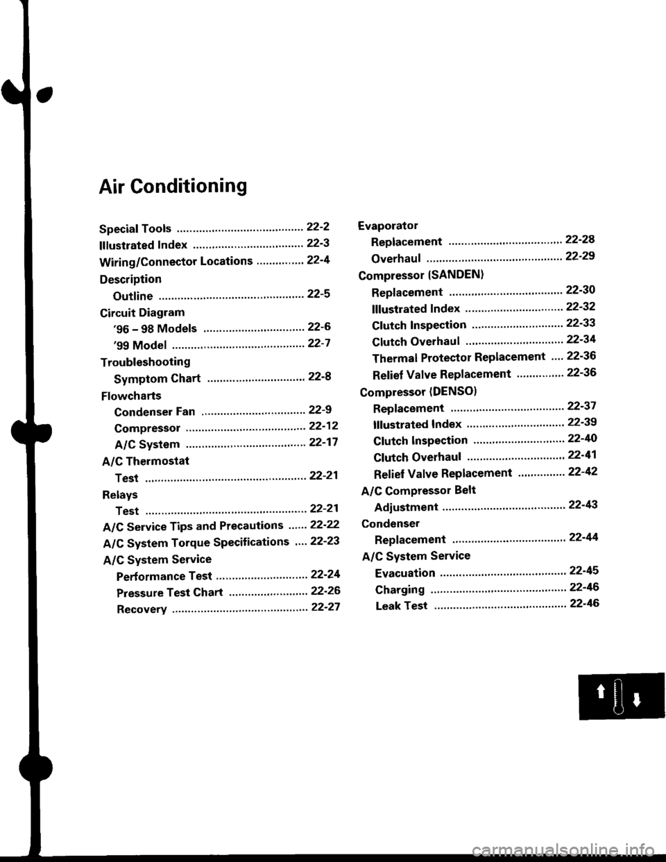
Speciaf Tools ......'.....' 22-2
f f f ustrated f ndex ......................... ".......' 22-3
Wiring/Connector Locations'.........'.... 22'4
Description
Outfine ............ .......22-s
Circuit Diagram
'96 - 98 Models ......"..........".......'.... 22-6
'99 Modef """""""' 22-7
Troubleshooting
Symptom Chart ".'......""................. 22-8
Flowcharts
Condenser Fan .........".................,..'. 22-9
Compressor .....""" 22-12
A/C System .........'.22'17
A/C Thermostat
Test ........'.......' """'22'21
Relays
Test ....."'......... ..""'22-21
A/C Service Tips and Precautions ......22-22
A/C System Torque Specifications '...22-23
A/C System Service
Performance Test ... '."......... ".... ....'..22-24
Pressure Test Chart .................. .... "' 22-26
Recovery ...".........," 22-27
Evaporator
Replacement .....",' 22'24
Overhauf .....-.....""' 22'29
Compressor {SANDEN}
Repf acement ......'.' 22-30
fffustrated fndex ......"..................'.... 22'32
Cf utch Inspection ......... "............ ...... 22-33
Clutch Overhau I ........................ ....... 22-34
Thermal Protector Replacement .... 22-36
Relief Valve Replacement ......'..."". 22-36
Compressor (DENSO)
Repfacement ..""',' 22-37
lf lustrated Index ............................... 22-39
Clutch lnspection ............."'...... "'.... 22-40
Cf utch Overhaul .....................'......... 22-41
Ref ief Valve Replacement'..'......"'.. 22-42
A/C Compressor Belt
Adiustment ............22'43
Condenser
Repfacement .......,,22'44
A/C System Service
Evacuation ...,,,.......22-45
Charging '..........--'..22'46
Leak rest """""""'22-46
Page 1426 of 2189
Special Tools
Bef. No. Tool NumberDescriptionQty I Page Reference
o
@
*07JGG - 00l0l0A
07sAz - 0010004
07947 - 6340300
07965 - 6920500
Belt Tension Gauge
Backprobe Set
Driver Attachment
Hub Assembly Gulde Attachment
1
'1
1
22-43
22-14,16
22-34
22-35' Included in the Belt Tension cauge Set, 07TGG-0010004.
a6r
L
3r
22-2