Page 896 of 2189
Description
Hydraulic Flow (cont'dl
E position
Reverse Inhibitor Conirol
lf the E position is selected while the veiicle is moving forward at speeds over 6 mph (10 km/h), the inhibitor solenoiddoesn't turn off by means of the TcM or PCM Reverse inhibitor pressure (Rl) is not applied to the reverse inhibitor valveas the reverse inhibitor solenoid turns on. The reverse inhibitor valve is kept on the right side, and covers the pon ro sropreverse brake pressure {RVS} to the reverse brake from the manual valve. Reverse brike pressure (RVs) i; not appried tothe reverse brake, and power is not transmitted to the reverse direction.
NOTE: When used, "left,' or,,right,, indicates direction on the hydraulic circuit.
14-218
Page 898 of 2189

Description
Hydraulic Flow (cont'd)
lll position, when th€ electronic control system is fauhy.
when the electronic control svstem (linear solenoids and sensors) is faulty, the transmission uses the pitot pipe pressure(PP) to 311o- rh" u"hicle to drive.
when all linear solenoids and sensors are off because of a faulty electronrc control system, clutch reducing pressure (cR)flows to the start clutch control valve, the manual valve, the PH-PL control valve, and the shift control valve. clutch reduc-ing pressure (cR) becomes shift varve pressure (sV) at the shift contror varve, and shift varve pressure {sv) is appried tothe left end of the shift valve and the right end of the shift inhibitor valve. The shift valve moves to the right side. anduncovers the pon that leads high pressure (PH) to the drive pulley and uncovers the po.t tlr"t r""1" ro,,"-pressure (pL) tothe driven pulley At this time, the pulley ratio is high, The shift inhibitor valve moves to the left side, and uncovers theport that leads shift inhibitor pressure (Sll to the pitot lubrication pipe and the pitot regulator valve. tne prtot lubricationpipe discharges fluid inside of the pitot flange, and discharged fluid enters into the pitot pipe and it is applied to the leftend of the pitot regulator valve. The pitot regulator valve moves lo the right side, and uncovers the port that leads pitotregulator pressure (PR) to the shift inhibitor valve. Pitot regulator pressure {pR) becomes start clutch pressure {sc1 at theshift inhibitor valve, and is applied to the stan clutch. The stan clutch rs engaged. The forward clutch pressure (FWD) isapplied to the forward crutch, and the forward crutch is engaged. This alows the vehicre to drive.
NOTE: When used. "|eft" or ,,right', indicates direction on the hydraulic circuit.
14-220
I.
Page 900 of 2189
Description
Park Mechanism
The park mechanism locks the transmission by engaging the park pawl with the park gear which is integral with the sec-ondary drive gear' The secondary drive gear engages with the secondary driven gear which engages wit-h the final drivengear.
shifting to E position causes the park cone (installed at the end of the park rod) to press the park pawl onto the park gear.Even if the end of the park pawl rides on the top of the park gear teeth, slight movement of the vehicle will cause the parkpawl and the park gear to mesh with each other completely because the park cone receives the tension from the park rodspring The park pawl receives the tension (which acts to separate the park pawl from the park gear) from the park pawlspring.
PARK PAWI-
PARK CONE
START CLUTCH
PABK GEAR
PARK RODPARK PAWL
PARK ROOSPRING
14-222
D
Page 906 of 2189

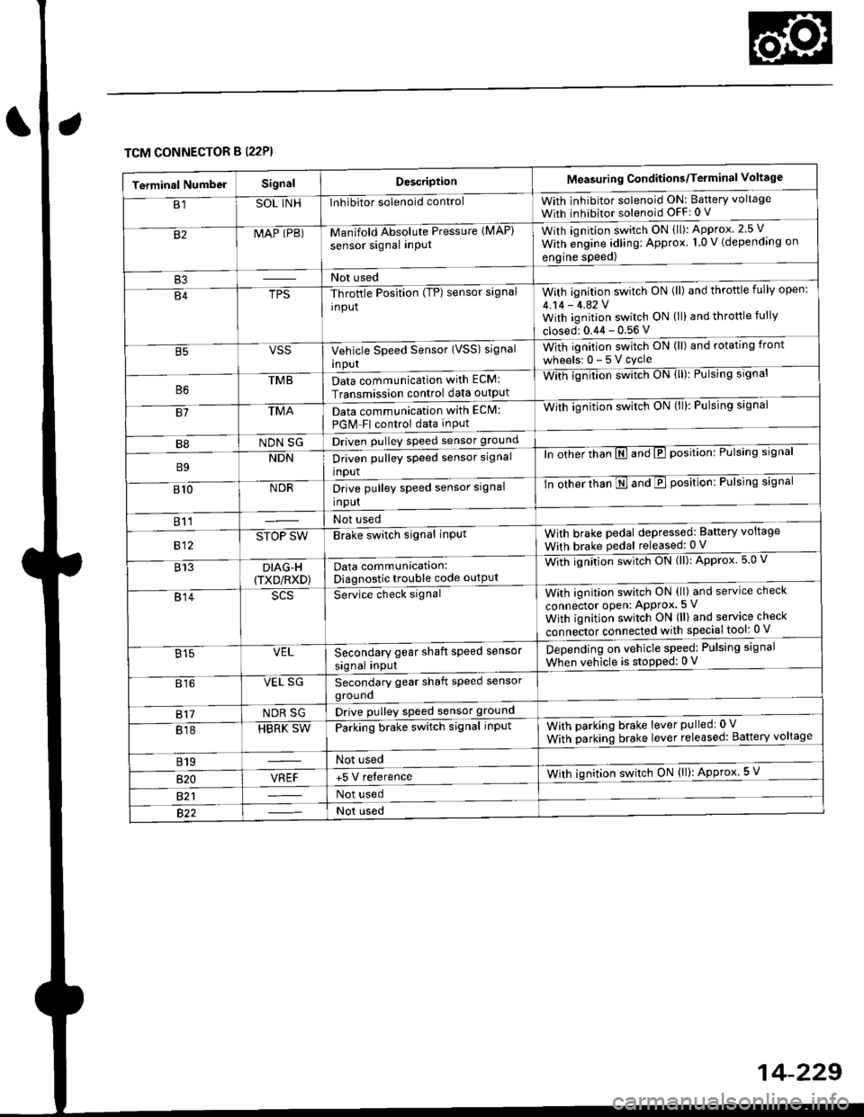
TCM CONNECTOR B (22P}
Terminal NumbelSignalDescriptionMeasuring Conditions/Terminal Voltage
B1SOL INHInhibitor solenoid controlWith inhibitor solenoid ON: Baftery voltage
With inhibitor solenoid OFF: 0 V
82MAP (PB)-M an if old Absol r-rte Pressure IMAP)
sensor signal inPUtWith iqnition switch ON (ll): Approx.2.5 V
With e;gine adling: Approx. 1.0 V (depending on
engine speed)
B3Not used
B4TPS-Throttle Position (TP) sensor signal
input
With ignition switch ON (ll) and throftle fully open:
4.14 - 4.42 VWith ignition switch ON (ll) and throttle fully
closed: 0.44 - 0.56 V
VSSVehicle Speed Sensor (VSS) signal
Inpur
With ignition switch ON (ll) and rotating front
wheelsr 0-5Vcycle
TMBData communication with ECM:
Transmission control data outpUt
With ignilion swltch UN lll): rulslng slgnar
81TMAData communication with EClvl:
PGM Fl control data inPut
With ignition swltch uN {ll,: l-ulslng slgnal
B8NDN SGDriven pulley speed sensor ground
B9NDNDriven pulley speed sensor signal
input
ln other thTnE and E position: Pulsing signal
810NDRDrive pulley speed sensor signal
Input
-tn ottrer ttran E ana E position: Pulsing signal
811Not used
812STOP SWBrake switch signal inPutWith brake pedal depressed: Battery voltage
With brake pedal released: 0 V
813DIAG-H(TXD/RXD)Data communication:Diagnostic trouble code outPut
Wittr ignitio.r s*itct' ON (ll): Approx 5.0 V
814Se-ice ctrect signatWith ignition switch ON (ll) and service check
connector oPen: APProx.5 V
With iqnition switch ON (ll) and service check
"onn"itot. connect"d with special tool: 0 V
Secondary gear shaft speed sensor
signal input
Depending on vehicle speed: Pulsing signal
When vehicle is stoPped: 0 V815VEL
816VEL SGSecondary gear shaft speed sensorgrouno
817NDR SGDrive pulley speed sensor ground
818HBRK SWParking brake switch signal inPutWith parking brake lever pulledr 0 V
With parking brake lever released: Battery voltage
819Not used
B�20VREF+5 V relerenceWith ignition switch ON (ll): Approx 5 V
821Not used
Not used
Page 909 of 2189

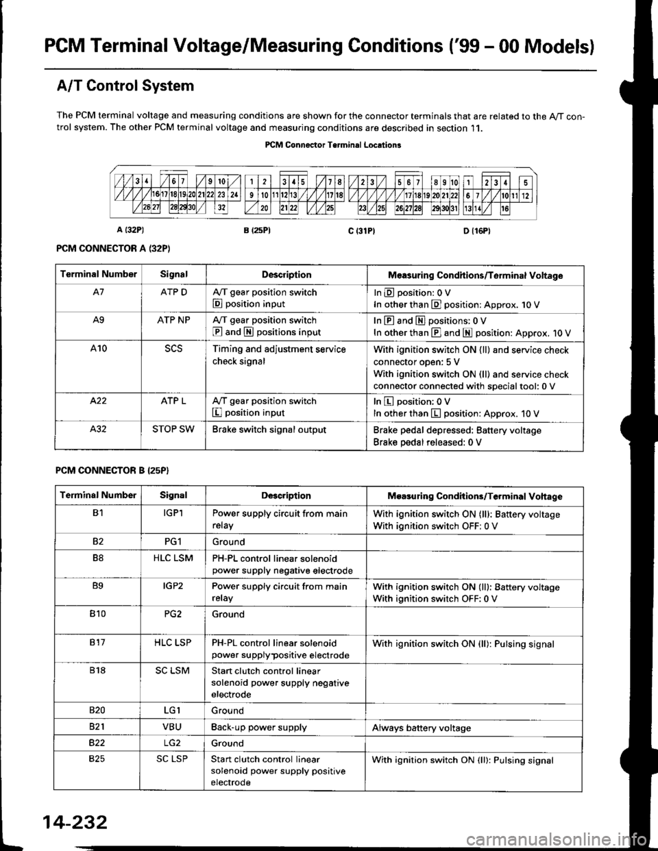
PGM Terminal Voltage/Measuring Conditions ('99 - 00 Modelsl
A/T Control System
The PCM terminal voltage and measuring conditions are shown for the connector terminals that are related to the A/T con-trol system. The other PCM terminal voltage and measuring conditions are described in section 11.
PICM Connoctor Terminrl Location3
Terminal NumberSignalDescriplionMeasuring Condhions/Torminal Voltage
A7ATP DA,/T gear position switch
E position input
InEposition:OV
In other than E] position: Approx. 1O V
A9ATP NPA/T gear position switch
@ and S positions input
In E and El positions: 0 V
In other than E] and E position: Approx. 1O V
A10Timing and adjustment service
check signal
With ignition switch ON {ll} and service check
connector oDen: 5 V
With ignition switch ON (ll) and service check
connector connected with soecialtool:0 v
ATP LA,/T gear position switch
I position input
In E position; OV
In other than E position: Approx. 10 V
STOP SWBrake switch signal outputBrake pedal depressed: Battery voltage
Brake pedal released: 0 V
PCM CONNECTOR B I25P}
Terminal NumberSignalDescriptionMoasuring Condhions/Terminal Vohage
B1IGPlPower supply circuit from main
relay
With ignition switch ON (lll: Battery voltage
With ignition switch OFF: 0 V
82PG1Ground
B8HLC LSMPH-PL control linear solenoidpower supply neqative electrode
B9IGP2Power supply circuit from main
relay
With ignition switch ON (lll: Battery voltage
With ignition switch OFF:0 V
810PG2Ground
817HLC LSPPH-PL control linear solenoid
power supplypositive electrode
With ignition switch ON {ll): Pulsing signal
818SC LSMStart clutch control linear
solenoid power supply negative
electrode
s20LGIGround
821VBUBack-up power supplyAlways battery voltage
B22Ground
825SC LSPStan clutch control linear
solenoid power supply positive
electrode
With ignition switch ON (ll): Pulsing signal
t
14-232
Page 910 of 2189
![HONDA CIVIC 1999 6.G Workshop Manual \a
PCM CONNECTOR D {16P)
14-233
Terminal Numbs]SignalDescriptionMeasuring Conditions/Terminal Voltage
D1VELSecondary gear shaft speed
sensor signal input
Depending on vehicle speed: Pulsing signal
Whe HONDA CIVIC 1999 6.G Workshop Manual \a
PCM CONNECTOR D {16P)
14-233
Terminal Numbs]SignalDescriptionMeasuring Conditions/Terminal Voltage
D1VELSecondary gear shaft speed
sensor signal input
Depending on vehicle speed: Pulsing signal
Whe](/manual-img/13/6068/w960_6068-909.png)
\a
PCM CONNECTOR D {16P)
14-233
Terminal Numbs]SignalDescriptionMeasuring Conditions/Terminal Voltage
D1VELSecondary gear shaft speed
sensor signal input
Depending on vehicle speed: Pulsing signal
When vehicle is stoPPed: APProx. 0 V
02SOL INHlnhibitor solenoid controlWith inhibitor solenoid ON: Battery voltage
With inhibitor solenoid OFF: 0 V
D3SH LSMShift control linear solenoid
power supply negative electrode
D4SH LSPShift control linear solenoid
power supply positive electrode
With ignition switch ON (ll): Pulsing signal
D5VB SOLPower supply for solenoid valvesWith ignition switch ON (ll): Baftery voltage
With ignition switch OFF:0 V
D6ATP RA,/T gear position switch E
position input
InEposition:0V
In other than B position; Approx. 10 V
D]VEL SGSecondary gear shaft sPeed
sensor ground
D8Not used
D9Not used
D10NDNDriven pulley speed sensor signal
anput
In other than E and E position: Pulsing signal
D11NDRDriven pulley speed sensor signal
input
ln other than E and E position: Pulsing signal
D12NDR SGDrive pulley speed sensor ground
D13ATP SA,/T gear position switch E
position input
InE position: 0V
In other than E position: Battery voltage
D14D INDD indicator light controlWhen ignition switch is first turned ON (ll):
Battery voltage for two seconds
In E position: Battery voltage
D15Not used
D16NDN SGDriven pulley speed sensor
grou nd
Page 1035 of 2189
Special Tools
Ref. No. I Tool NumberDescriptionOty I Remark
o
@,a
\9'
o
@
@
07JAF - SH20400
07LAD - PW50601
07MAC - S100200
07746 - 0010300
07746 - 0010400
07746 - 0030400
07749 - 0010000
07965 - SD90100
07xAc - 0010100
Support Base Attachment
Inner Race Driver
Ball Joint Remover, 28 mm
Driver Attachment, 42 x 47 mm
Driver Attachment, 52 x 55 mm
Driver Attachment, 35 mm l.D.
Handle Driver
Support Base
Threaded Adapter, 22 x 1.5 mm
1
1
1
1
I
I
1
I
1
@e
@
&
w
@
@
c
6
@
'
lo,
c[G)
8-)
ge
l..---,l
G)
16-2
Page 1057 of 2189

l.
t
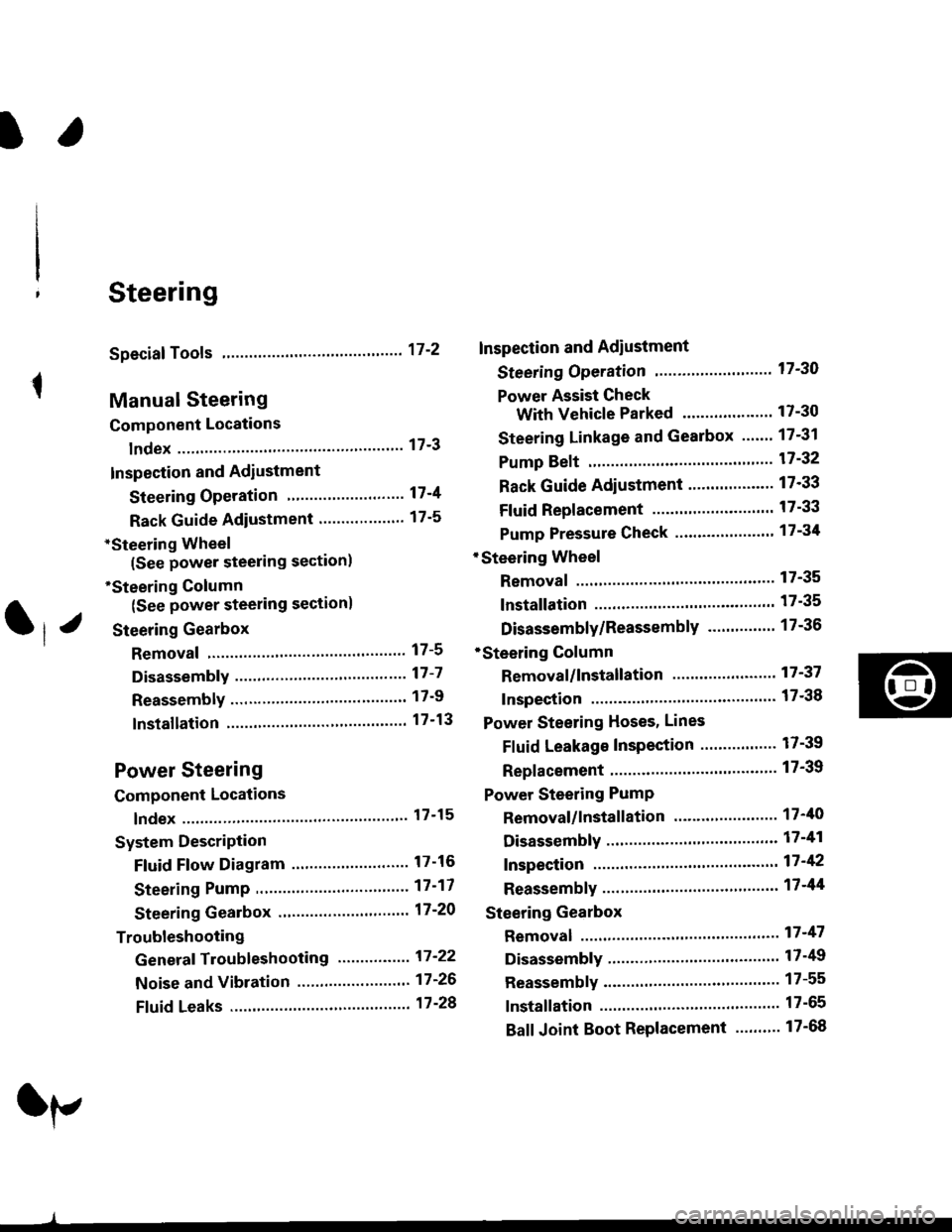
Steering
Speciaf Tools ....."'.....17-2
Manual Steering
Component Locations
lndex ................ ....... 17-3
Inspection and Adiustment
Steering Operation "'......"............... 17-4
Rack Guide Adiustment ................... 17-5
*Steering Wheel
(See power steering section)
*Steering Column
(See power steering sectionl
Steering Gearbox
Removal ................. 17-5
Disassembly ......."" 17-7
ReassemblY ..'......... 17-9
lnstallation ............. 17-13
Power Steering
Component Locations
lndex "......."..... """' 17-15
System DescriPtion
Fluid Flow Diagram .........""............. 17'16
Steering Pump ............'... "........"'...-- 17 -17
Steering Gearbox .".................'...'.'.' 17-20
Troubleshooting
Generaf Troubleshooting ..........--.... 17'22
Noise and Vibration ......................... 17 -26
Ffuid Leaks .............17-28
Inspection and Adiustment
Steering Operation'......."'........'...... 1 7-30
Power Assist Check
With Vehicle Parked .."................ 17-30
Steering Linkage and Gearbox ....." 17-31
Pump Beft ...--.""".. 17-32
Rack Guide Adiustment .'.......'.......'. 17'33
Fluid Replacement .....'.."................. 17-33
Pump Pressure Check .............'....-. " 17 -34
'Steering Wheel
Removal .."'........'... 17-35
lnstallation ............. 17-35
Disassembly/Reassembly ......'.....'.' 17-36
*Steering Column
Removal/lnstallation ....'........... ---.... 17'37
lnspection .............. 17'38
Power Steering Hoses, Lines
Fluid Leakage Inspeetion ............'.... 17-39
Replacement ......".. 17-39
Power Steering PumP
Removal/lnstallation .'.'..'..'............. 17-40
Disassembly ".........17-41
fnspection .......---'." 17'42
Reassembly ..'.........17-44
Steering Gearbox
Removal ....'........."' 17'47
DisassemblY ..........' 17-49
Reassembly '........... 17-55
lnstallation ............. 17-65
Ball Joint Boot Replacement .......'.. 17-68
Ir/
lp