1999 HONDA CIVIC link
[x] Cancel search: linkPage 1752 of 2189
Troubleshooting
J
J
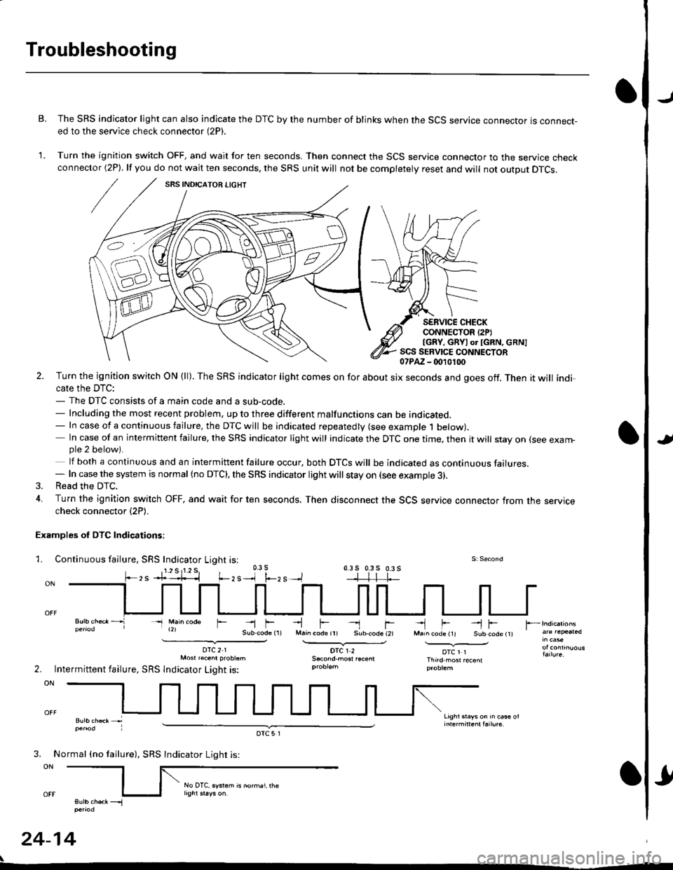
B. The SRS indicator light can also indicate the DTC by the number of blinks when the SCS service connector is connect-ed to the service check connector (2P).
1. Turn the ignition switch OFF, and wait for ten seconds. Then connect the SCS service connector to the service checkconnector (2P). lf you do not wait ten seconds, the SRS unit will not be completely reset and will not output DTCS.
SERVICE CHECKCONNECTOR {2PIIGRY, GRYI or IGRN, cRN]SCS SERVICE CONNECTOR07PAZ - (m10100
l.-zs
2. Turn the ignition switch ON (ll). The SRS indicator light comes on for about six seconds and goes off. Then it will indi,cate the DTC:- The DTC consists of a main code and a sub-code.- Including the most recent problem, up to three different malfunctions can be indicated.- In case of a continuous failure, the DTC will be indicated repeatedly (see example 1 below).- In case of an intermittent failure, the SRS indicator light will indicate the DTC one time, then it will stay on (see exam-ple 2 below).
lf both a continuous and an intermittent failure occur, both DTCS will be indicated as continuous failures.- In case the system is normal (no DTC), the SRS indicator light will stay on (see example 3).3. Read the DTC.
4. Turn the ignition switch OFF, and wait for ten seconds. Then disconnect the SCS service connector from the servicecheck connector (2P).
Examples of DTC Indications:
1. Continuous fallure, SRS Indicator Light isl
- Main @de
DTC21Mosr raenr probtsm
Intermittent failure, SRS lndicator Light is:
-lF- rM.in code ir) Sub.code (2)
DTCI2
-'l F --l FMarn code (11 Sub code t1t
DTCl1Thnd.most recenl
Lrghr srays on rn ca* ol
r --
2.
3. No
ON
sutb chek __.1penod
24-14
rmal (no failure), SRS
DTC5l
Indicator Light is:
rl
No OTC, system is norhal, rhe
Page 1753 of 2189
)Erasing the DTC Memory
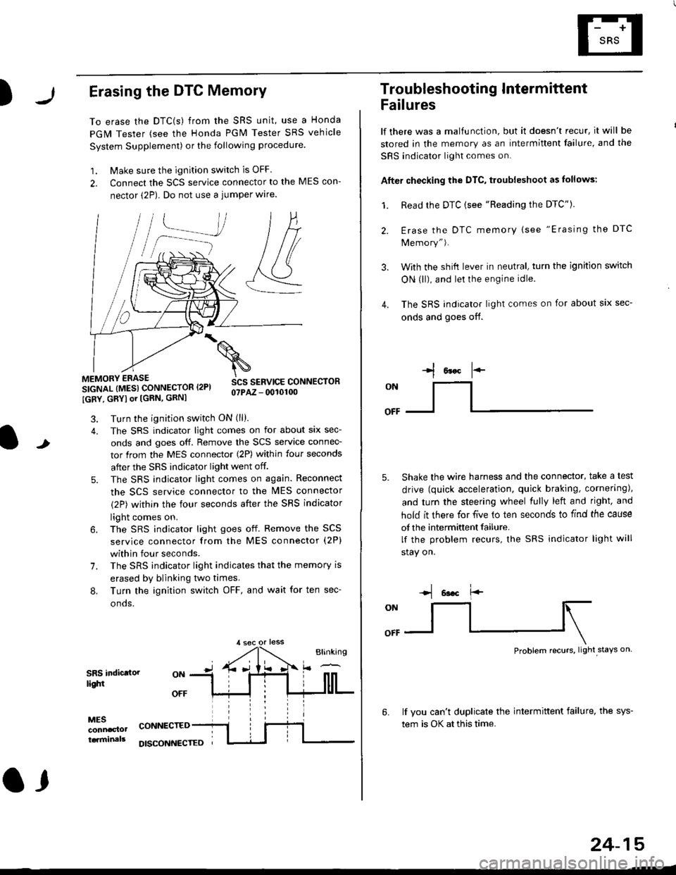
To erase the DTC(s) from the SRS unit, use a Honda
PGM Tester (see the Honda PGM Tester SRS vehicle
System Supplement) or the following procedure
1. Make sure the ignition switch is OFF
2. Connect the SCS service connector to the MES con-
nector (2P). Do not use a jumper wlre.
]P,
&
.!--J
MEMORY ERASE
SIGNAL (MESI CONNECTOR I2PI
IGRY, GRYI or [GRN, GRNI
SCS SERVICE CONNECTORo?PAZ - 0010100
t
7.
Turn the ignition switch ON (ll).
The SRS indicator light comes on for about six sec-
onds and goes off. Remove the SCS service connec-
tor from the MES connector (2P) within four seconds
after the SRS indicator light went off.
The SRS indicator light comes on again. Reconnect
the SCS service connector to the lvlES connector
(2P) within the four seconds after the SRS indicator
light comes on.
The SRS indicator light goes off. Remove the SCS
service connector from the MES connector (2P)
within four seconds.
The SRS indicator light indicates that the memory is
erased by blinking two times.
Turn the ignition switch OFF, and wait for ten sec-
onos.
8.
SRS indictlorlighi
MESconncclottcaminals
CONNECTED
O,
DISCONI{ECTED
24-15
Troubleshooting Intermittent
Failures
lf there was a malfunction, but it doesn't recur, it will be
stored in the memory as an intermittent failure, and the
SRS indicator light comes on.
Afte. checking the DTC, troubleshoot as lollows:
1. Read rhe DTC {see "Reading the DTC"}.
Erase the DTC memory (see "Erasing the DTC
Memory").
With the shifi lever in neutral, turn the ignition switch
ON (ll), and lei the engine idle.
The SRS indicator light comes on for about six sec-
onds and goes off.
l*F
ON
tl-- -l
Shake the wire harness and the connector, take a test
drive (quick acceleration, quick braking, cornering),
and turn the steering wheel fully left and right, and
hold it there for five lo ten seconds to find the cause
of the intermittent failure.
lf the problem recurs, the SRS indicator light will
stay on.
-q 6a.c f'-
:q
Problem recurs, light stays on
3.
4.
6.lf vou can't duplicate the intermittent failure, the sys-
tem is OK at this time.
Page 1840 of 2189

Ground-to-Components I ndex
f.,lONOTE: All ground wires are BLK unless otherwise noted.
GroundPageComponents or Circuit Grounded
Battery (BLKYEL)
Steering pump bracket
t+-rg ITransmission housing
l
G101
(-1)
G101
(-2)
14-2
and
14-3
ano
14-1
Powertrain or engine control module (PG1 and pG2 are BLK: LG1 and LG2 are
BRN/BLK), EGR control solenoid valve (CW, EGR valve and lift sensor (Dt6yS enginewith M,/T), Engine coolant temperature switch, pGM-Fl main relay, power steeringpressure switch (USA), Primary HO2S (D16Y5 engine with l\/,/T), Vehicle speed sensor,VTEC pressure switch (D16Y5/D16Y8 engines), CKF sensor (BRN/BLK), Transmission
control module (CYf) (Pc1 is BLK: LG1 is BRN/BLK)
Shielding betvveen the PCM or ECM and these components (all have BRN/BLK wires):
CKF sensor, TDC/CKP/CYP sensor. Primary and secondary heated oxygen sensors.
Knock sensor (CWDl6YB engine), Mainshaft speed sensor (AiT except CVT),
I Countershaft speed sensor (A/T except CVf)
Shielding between the TCM and these components (CVT) (all have BRN/BLK wires):
Drive pulley speed sensor, Driven pulley speed sensor, Secondary gear shaft
speed sensor
Powertrain or engine control module (PG1 and pG2 are BLK; LG1 and LGz are
BRN/BLK), EGR control solenoid valve (D16Y5 engine), EGR valve (Dt685), Engine
coolant temperature switch, Fuel pressure regulator shut-off solenoid valve (D1685),
PGM-FI main relay, Power steering pressure switch (USA), Vehicle speed sensor, VTECpressure switch (All except D16Y7 engine), CKF sensor (A
except 81642) (BRN/BLK)
Shielding between the PCM or ECM and these components (all have BRN/BLK wires):
CKF sensor, TDC/CKP/CYP sensor, Primary and secondary heated oxygen sensors,
Knock sensor (All except D16Y7 engine), i/ainshaft speed sensor (Arf except CW),
Countershaft speed sensor (A,/T except CVf), Drive pulley speed sensor (CW), Drivenpulley speed sensor (CVT), Secondary gear shaft speed sensor (CVf)
I Badiator fan motor, Right front parking/turn signat tight, Right headtight
G20214-4I Cruise control actuator, Left front parking/turn signal lights, Left headlight, Rear window
I washer motor, Windshield washer motor, Washer fluid level switch (,99-'00 Canada)
G401| +-o
and
14-7
Accessory power socket, Brake fluid level switch, Clutch interlock switch (M/T), Clutchswitch (lillT with cruise/D16Y5 engine with MfD, Combination wiper switch (Z wires),
Cruise control main switch, Cruise control unit, Dash lights brightness controller, Data
link connector, Daytime running lights control unit (Canada), Gauge assembly, Horn('96-'97 models), Integrated control unit, Interlock control unit (ArI), Keyless door lock
control unit ('99-'00 models with keyless), Moonroof close and open relays, Moonroof
switch, Park pin switch (A/r), Power window relay, Rear window defogger relay, Rear
window defogger switch ('96-'98 models), Steering lock, Stereo radio tuner (,96-,98
USA: LX, EX, and HX), Turn signal/hazard relay, Windshield wiper motor.....plus
everything grounded through G402
6-6
Page 1852 of 2189
Power Distribution
- From Fuses to Relays and Components (cont'd)
-",JX-
I
I
\FUSE '3n{fEtbRUC|{T7.'.4
FUSE 44FI EA'!aacoa Dr6lc)
FUSE il8POUGNtvtl|Do{taoa
c351
c420PHOTO 63
I-.:CrJ
WIIT/ELX
1
I
I
I
I
FUELINJECTIONRELAYPage 25-1PHOTO 135
DATA LINKCONNECTOR(DLc)
Page 23-4,24-4, ot 25-4PHOfO 5001685 engine -
c419PHOTO 63
UNDER.DASHFUSE/RELAYBOXPHO|Q 5A
POWEBw]tDowNELAYPagE 120H$fa8
L-- ----- --20
wlIT/RED
-t
c420 6PHO|O 63vtEw 53
WHT/FEO
c407PHOTO 52Y|EW 2 ( 9& 00 modsrs)
c5s'rPHO|O 63
L-----JU DEN.DASHFUSE/RELAY BOXPHOfO 58
To Fuses 7, 8, 1 0, and I 1 ;tor deiails, s8€ PowerVYindotts, pa$ 120.
HatchbackCoup€ & S€dan
WHT/FED
(Sedan 1)
(e6-
101
,,, tr:::--*''.:lltut
(Not used)
i--l
tlL--J
TRUNKLIGHTPage 114-3
tl
tl
SPOT.LIGHTSPage 114-3
tl
tl
CEILINGLIGHTPage 114-3
* = Male-Femaleterminalsreversed for'99-'00 models
7A
tl
tl
PGM-FI MAINRELAYPage 23.24, ot 25
vtLw 18
I
I
PGM-FIRELAYPage 2324, ot 22
vtLw 18
i-,-x;-l
icontac{i
tlINTEGNATED
l__i!ffi*
10-10
Page 1863 of 2189
Ground Distributioh (conrd)
)
- G401
NOTE:
To G402on page14-5.
WINOSHIELOWIPERMOTORPage 91-1
DAYTIMERUNNINGLIGHTS
99.!rRoL cLUrcHuNr I swtTcH:?99^ Pases 23-5and 34-3vtEw 66 PHA|A 55
I
I
INJECTORCONTROLMODULEPage 25-1
I
I
3
. Wires shown without color codes are black.
o On Coupe and Sedan models, G401 is represented by ring terminals.
tl
tl
INTER.LOCK6611p99 PARKUN|T PINpaoe j38 SWITCHor ige_t Page 138PHoro6s of 138-1vtEw 26 PHOfO /7r-1 r-'t
tttl
CLUTCHINTER-LOCKSWITCHPage 21-2
ll
ll
ttl
rll
I
Itttl
'Ll;
I
n
t
M/T with 01685Cruise/D16Y5enginewith M/T
BRAKEFLUIDLEVELswtTcHPage 71ot 71-1
tl
tl
DOOR LOCK .CONTROLSTEERINGLOCKPage /3
tl
tl
UNITPage 130-12 ;
ttl
tt:
models
RNte 40
I
I
(
I
I czor
l'i1l?,
'97 mo
HORNPage 4
I
I
NFnl
s 9c.Plv'
BLK/RED
t
IJ;--
',f-l
DATA LINKCONNECTOR(DLC)Pages 23-4,24-4,25 4,44-1, and 47
30
14-6
G401
Page 1884 of 2189
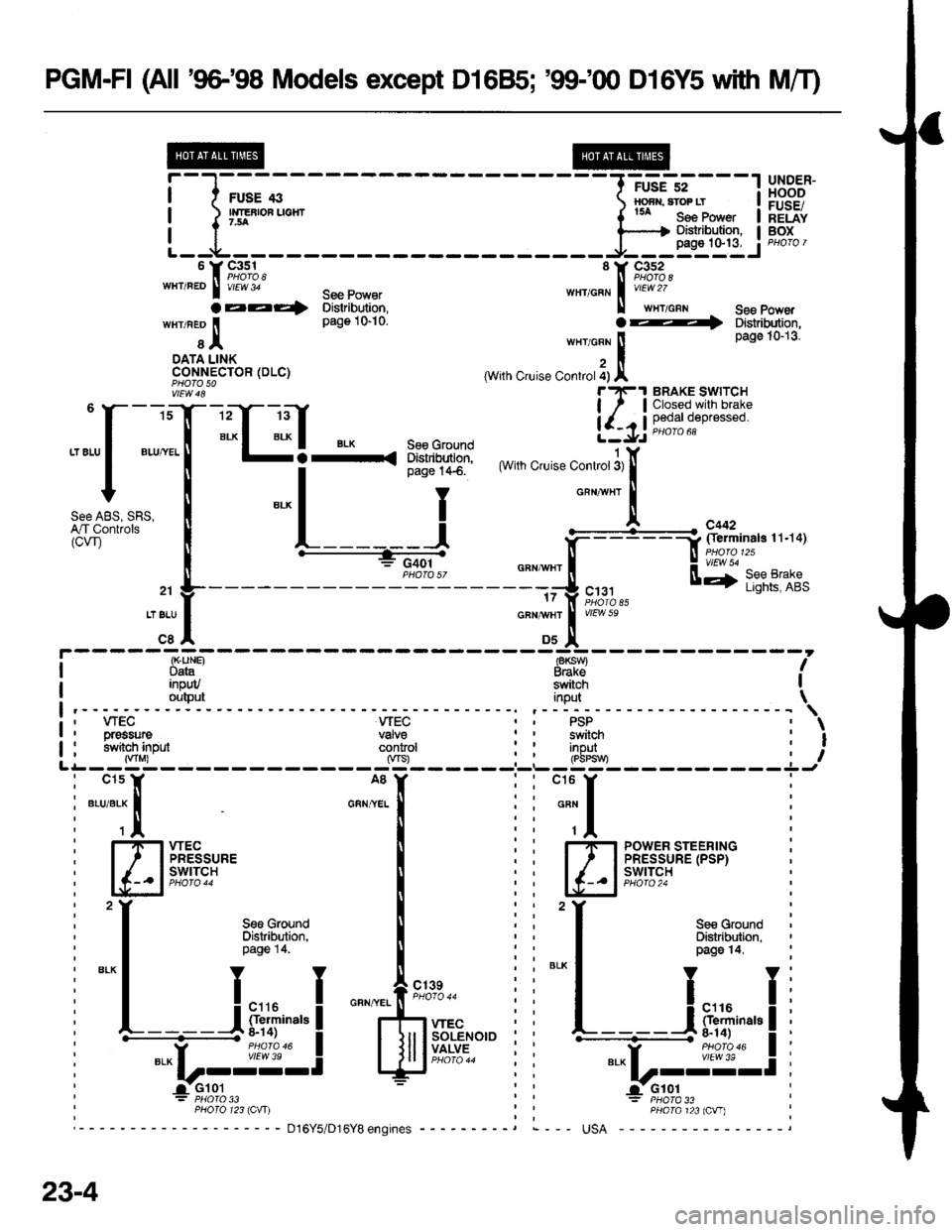
PGM-FI (All '9G'98 Models except D16B5; '99100 D16Y5 with MfI)
1@
i-l-,;;*--
L--LT-:
UNDER-HOODFUSE/RELAYBOX
'f 9;u;, '11 ,c,i"',3,wHT'REo I rrEt3' see Powar wHr/cFN I vrF 2/
aaa4 Distdbution, ll wxTcnr See power
wnineo I page 1S10. art Distibution,
r I ,r"ro"" ! Page 10-13
DATA LINK , ICONI€CTOR (DLC) (With Cruise Controt i) |vtEw 48 rrF.t BRAKE SWtTCh
" ""f ":T
-C-l*
ffif{"s1 ** ".,*.-,lf,1i
Fi3:{i'r'rs35:
,""oL.rr. I *-l I
oauwxr
l
ffi;"i;ii" I t------j F=Ln&1?i,inars'.rqr
i
-----=ffi, o"n,n", I H ;,?fl:&'"
,, L----- --------=J ",., u+ lfii?iif.21 F----- - L'gitr! ^o
. 1z I irlot,b asTTELU I cRNu/Hr I v/EW )eIcel ouJl
inpWortsut
(K"UNB 18KSW)Data B.akeswitchinput
wEcvalveconkol
, WEGI orgssure: h,vitch inputinoutrPbPs
Ag
GRN/YEL
wEcPRESSUREswtTcH
POWER STEERINGPRESSURE (PSP)SWITCH
I ALK
Sg€ GroundDistribltion,page 14,
iu,**,"L_jFiF,""*l
*.u_-ig:-l
d'Gr01
23-4
PHO|O 123 IClr|)
Page 1899 of 2189
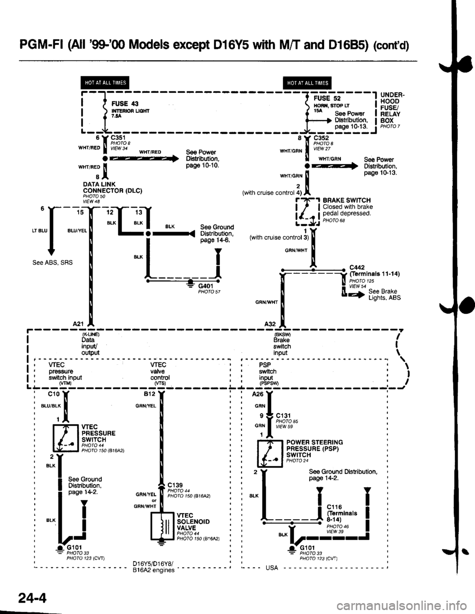
PGM-FI (All '9$"q) Models except D16Y5 with M/T and D1685) (cont'd)
@@
i-l;;--
----1-:::=*"---l
!,8,:"ff
| )'rEnsuorr ( tu seo Power I hEiiY
'r9,1%, 'r F,1%,wHr/FEo I v/El/v 34 'HT/FED s€e power w111,6s1 | vtew zz
a 1 oistribution, ll wrlcnr See power
wrr neo I pa$iGio. OF+ DstnbJtron.
t I tn"to"n ! Pa9o 1s13'
oAra LINK z llCONN-ECTOR (DLC) (with cruise controt 4) A
vtEw 48 t?e1 BRAKE SWTTCH
isT-rrT ltf !1.l'".e'.l;'[3J:5:
""[ ":T-:"C-l:.Frd*Fl
lll,
"""f "",T
""U]-t-.,-t-..*.",,""*^i:# [*iu'r;i:;r.';
'""o1""1 ""l
l ;f=:&ri'n"*,,.,0r
[
.---+_s,:.;-,
"*,**il [ff'ftrs,llr,
*,.!. ^* IA2r |' A32 A
: {r(LlN€) €KSW} |I Data Braksfleu.rt} ft svyl IData Braksinpuv switch Ioutput inpd \\' wEC VTEC PSP
I PHaro 123lcvr) D16y5/Dr6y8/ : : PHoro 123lcw)
---'- ei6A2'"noin"i ---- "--- usA
;
L
Dr€ssure vaNesrlitoh input conkol(Vnr) 0rs)
*{
---
"::l
fTlxlE8,u,. I
lc-- ll#il?i,",,*, I
"il
II see crouno
! Fi"frW """,*f,f,',11,r,",.*,
-'l
I
""""iJ,,.lff*u"'"
yi qr;;;i6;;o,E.6A',
: PHOTO 33
sYvltctlinDut
---u-r----
can I
s I crer
"Tl t#ffl","
I-'I-I POWER STEERINGI ' I PRESSURE (PSP)
lc_.ltg+I9i
,
f ff&G{lfd Drsribution,
""L----i
F*i,""," I.----a- -r*ro_*
|"," I vtEw 39
Lr----J
: PHATO 33
\
I
I
pag€ 142.
24-4
Page 1911 of 2189
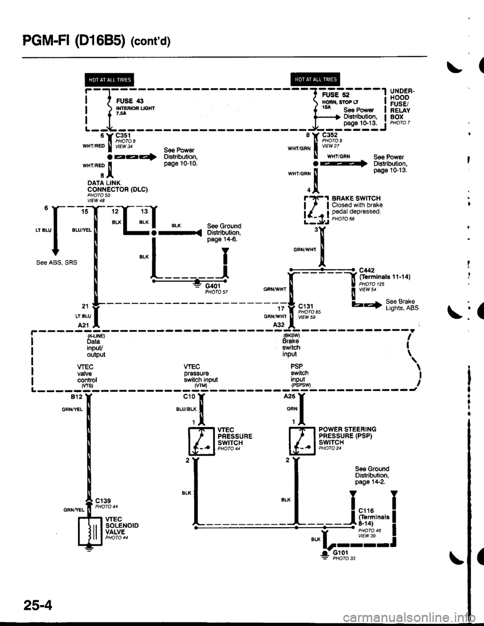
PGM-FI (D1685) (cont'd)
(
UNDER-HOODFUSE/RELAYBOX
Se3 PowetDistribution,pags 1&13-
uYt%%,
WHT/REO I vr6wJ,
aaz�4wxlnro I
sIDATA LINKcoNNECTOR (DLC)
8 Y C352ll Proro 8,""'o"n I u'* "
ll wwcnr
.4
*"r,o"., ll
IqA
S€E PowsrBistribution,pag€ 10-10.
i
ll
See ABS,
\:(
it31tlofo t'EW 59
c t31
vtEw 5!
F------: (x.irie Pt9q II oata Brakoainpuv switch I
output input \
\
II---J
POWER STEERINGPRESSURE (PSP)swtTcH
See GroundDistribution,pag€ 1+2.
WEC PSPprossure switchswitch inpllt inpui(wU) lPSPSvv)
;ry---
T
flffiii':Y- E"l 2
t--l "* |
t__________L
VIECvafuecontol
-----gl-812I'
GFN,^YEL
i
I
!
I
I
o"n,,,.f, F':t;"
r{r *."
I Jll l!,[.fi"'"l-i-J
l'?!-1 BRAKE SWTTCH
| / | Closed with brake
!-l-ij 9;'3,1ff'**""
'T
"*'-.1,
25-4