1999 HONDA CIVIC ect
[x] Cancel search: ectPage 1104 of 2189
Steering Gearbox
Removal {cont'dl
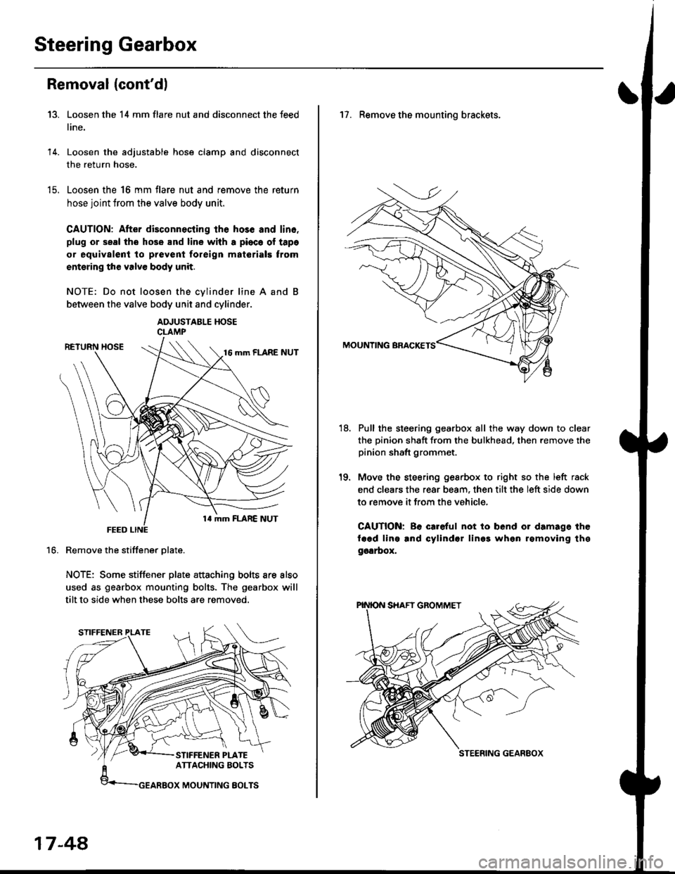
Loosen the 14 mm flare nut and disconnect the feed
line.
Loosen the adjustable hose clamp and disconnect
the return hose.
Loosen the 16 mm flare nut and remove the return
hose joint trom the valve body unit.
CAUTION: After disconnecting lhe hos6 and lin6.
plug or seal the hose and line with a pioca ol tapa
or equivalent to prevenl foreign matorials trom
entsring the valve body unit.
NOTE: Do not loosen the cvlinder line A and
between the valve body unit and cylinder.
ADJUSTABLE HOSECLAMP
Remove the stiffener Dlate.
NOTE: Some stiffener plate attaching bolts are also
used as gearbox mounting bolts. The gearbox will
tilt to side when these bolts are removed.
13.
14.
t9.
16.
17-48,
17. Remove the mounting brackets.
Pull the steering gearbox all the way down to clear
the pinion shaft from the bulkhead. then remove the
pinion shaft grommet.
Move the steering gesrbox to right so the left rack
end clears the rear beam, then tilt the left side down
to remove it from the vehicle,
CAUTION: Be careful not io bend or damage the
fagd ling and cylindsr lin99 whgn rgmoving thg
ggarbox,
18.
STEERING GEANEOX
Page 1107 of 2189
t
t5.
16.
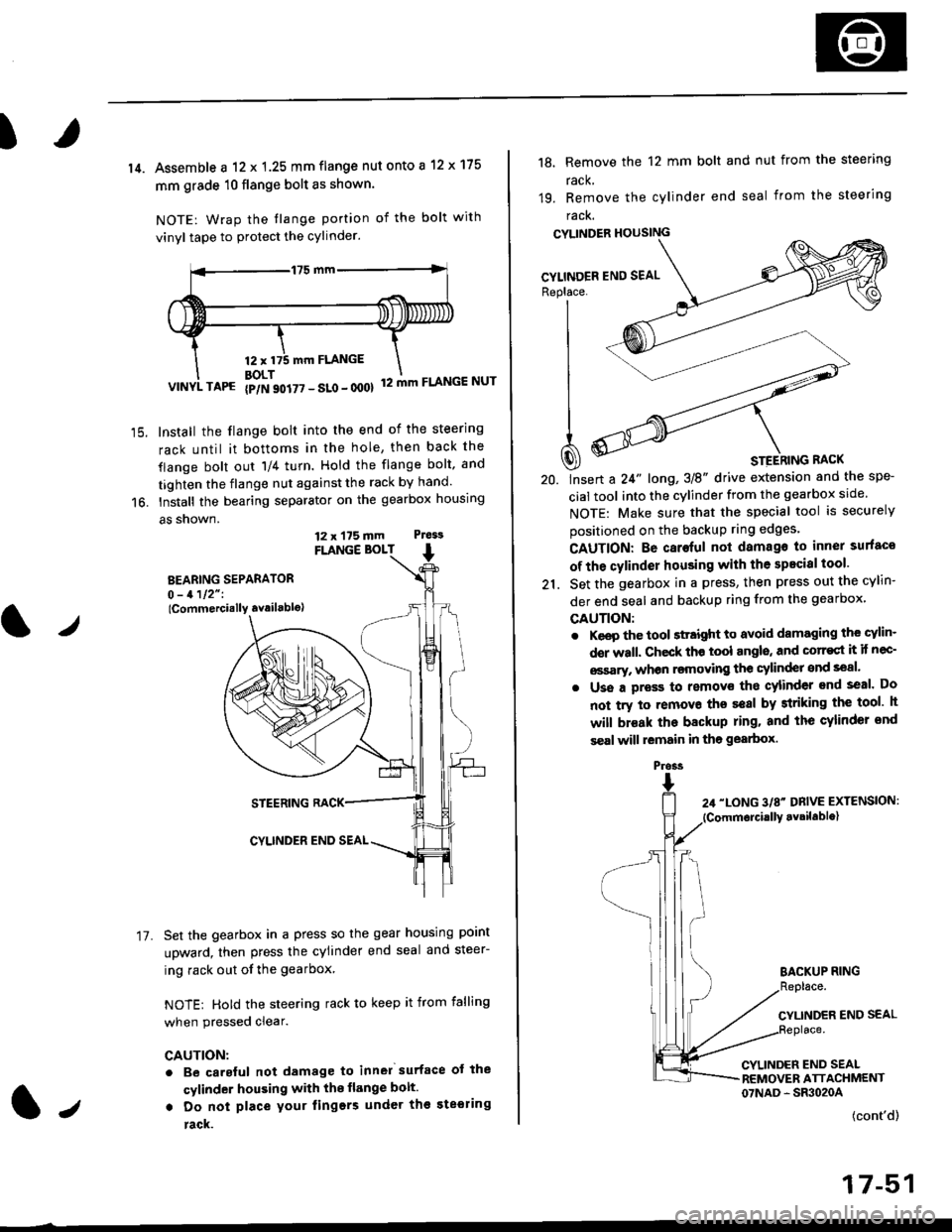
14. Assemble a 12 x 1.25 mm flange nut onto a 12 x 175
mm grade 10 flange bolt as shown.
NOTE: Wrap the tlange portion of the bolt with
vinyl tape to protect the cylinder.
12,mm FLANGE
BOLT12 mm FLANGE NUTVINYL TAPG {p/N 90i77 - SLo - 000}
Install the flange bolt into the end of the steering
rack until it bottoms in the hole, then back the
flange bolt out 'll4 turn. Hold the flange bolt, and
tighten the flange nut against the rack by hand.
Install the bearing separator on the gearbox housing
a5 snown.
FLANGE BOLT
BEARING SEPARATOR0 - 1112" I
lCommercially availablo)
STEERING RACK
CYLINDER END SEAL
Set the gearbox in a press so the gear housing point
upward, then press the cylinder end seal and steer-
ing rack out of the gearbox
NOTE: Hold the steering rack to keep it from falling
when pressed clear.
CAUTION:
. Be carsful not damage to inn6l surface ot the
cylinder housing with the flange bolt.
. Do not place your lingers under th€ ste€ring
rack.
t./
17.
12 x 175 mm Ptess
1.,
the spe-
srcle.
securely
Replace. J__--'- ,----)t'| ,-----'" ,-,-'-'| fiN ----'
| .Wl'----
I
t
-'4a
| ^--.'--4
A ooY----- \
Q) * srerhtnc nact
20. lnsert a 24" long,3E" drive extension and
cial tool into the cylinder from the gearbox
NOTE: Make sure that the special tool is
positioned on the backup ring edges'
18, Remove the 12 mm bolt and nut from the steering
rack,
19. Remove the cylinder end seal from the steering
racK.
CYLINDER HOUSING
CAUTION: Be caroful not damago to inner surfaco
of the cylinder housing with the specisl tool'
21. Set the gearbox in a press, then press out the cYlin-
der end seal and backup ring from the gearbox,
GAUTION:
. Keep the tool sttaight to avoid damaging the cylin'
der wall. Check th€ tool angls, and corr€st it if nec-
€ssary, whon rsmoving the cylinder snd seal.
. Uss a pross to removs tho cylinder end seal. Do
not try to removo ths seal by striking the tool h
will br€ak the backup ring. and the cylinder snd
s€al will lemain in tho gearbox.
BACKUP RING
CYLINDER END SEAL
CYLINDER END SEALREMOVER ATTACHMENT07NAD - SR3020A
(cont'd)
17-51
Pross
Page 1110 of 2189
Steering Gearbox
Disassembly (cont'd)
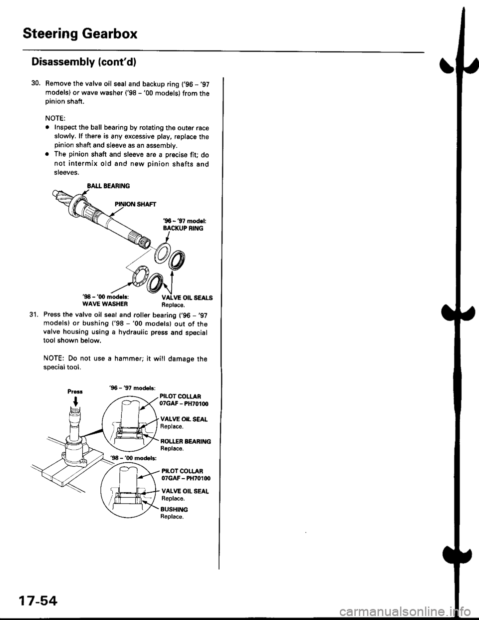
30. Bemove the valve oil seal and backup ring {'96 -'97
models) or wave washer ('98 -'00 models) from theoinion shaft.
NOTE:
. Inspect the ball bearing by rotating the outer race
slowly. lf there is any excessive play, replace thepinion shaft and sleeve as an assembly.
. The pinion shaft and sleeve are a precise fit; do
not intermix old and new pinion shafts and
steeves.
'98 - '(x) mod.lr:WAVE WASHERReplace.
31.Press the valve oil seal and roller bearing {'96 -,97
modelsl or bushing ('98 -'00 modelsl out of thevalve housing using a hydraulic press and specialtool shown below.
NOTE: Do not use a hammer; it will damage the
specialtool.
'96 - '97 modob:
PILOT COLLAR07GAF - PH70100
VAI.VE OIL SEALReplace.
BOI.I"ER BEARINGReplace.
PILOT COLLAR07GAF - PHtoroo
VALVE OII. SEALReplace.
BUSHINGBeplace.
BALL BEARING
'96 - '00 mod.b:
17-54
Page 1113 of 2189
I
14.
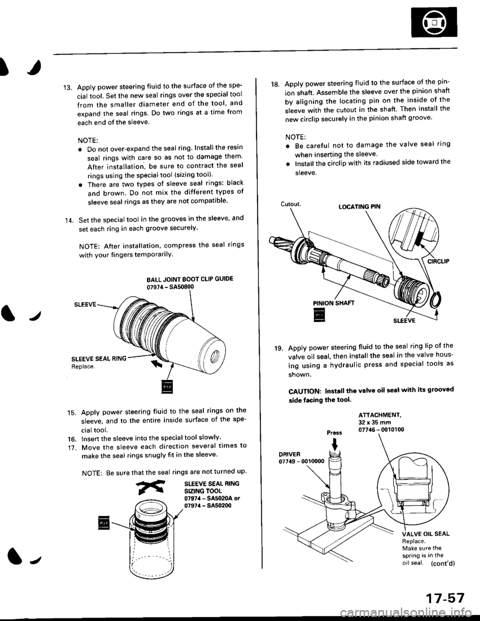
Apply power steering fluid to the surface of the spe-
cial tool. Set the new seal rings over the special tool
from the smaller diameter end of the tool, and
expand the seal rings. Do two rings at a time from
each end of the sleeve.
NOTE;
. Do not over-expand the seal ring. Installthe resin
seal rings with care so as not to damage them'
After installation, be sure to contract the seal
rings using the specialtool (sizing tool).
. There are two types of sleeve seal rings: black
and brown. Do not mix the different types of
sleeve seal rings as they are not compatible
Set the special tool in the grooves in the sleeve, and
set each ring in each groove securely.
NOTE: After installation, compress the seal rings
with your fingers temPorarilY
BALL JOINT BOOI CLIP GUIDE
07S7,1- SA50800
SLEEVE
15. Apply power steering fluid to the seal rings on the
sleeve, and to the entire inside surface of the spe-
cial tool.
16. lnsert the sleeve into the specialtool slowly'
17. Move the sleeve each direction several times to
make the seal rings snugly fit in the sleeve'
NOTE: Be surerings are not turned uP.
SITEVE SEAL RINGSIZING TOOL0797a - SA5020A or07974 - SA50200
that the seal
fr
J
17-57
18. Apply power steering fluid to the surface o{ the pin-
ion shaft. Assemble the sleeve over the pinion shaft
by aligning the locating pin on the inside of the
sleeve with the cutout in the shaft. Then install the
new circlip securely in the pinion shaft groove'
NOTE:
Be careful not to damage the valve seal ring
when inserting the sleeve.
Installthe circlip with its radiused side toward the
sleeve.
Apply power steering fluid to the seal ring lip of the
valve oil seal. then install the seal in the valve hous-
ing using a hydraulic press and special tools as
shown.
CAUTION: Install the valve oil seal with its grooved
side facing the tool.
'19.
ATTACHMENT.32x35mm0774.6 - q)101(x)Pre3s
IDRIVER07749 - 0010000
VALVE OIL SEALReplace.Make sure thespring is in the
oil seal. (cont'd)
Page 1117 of 2189
)
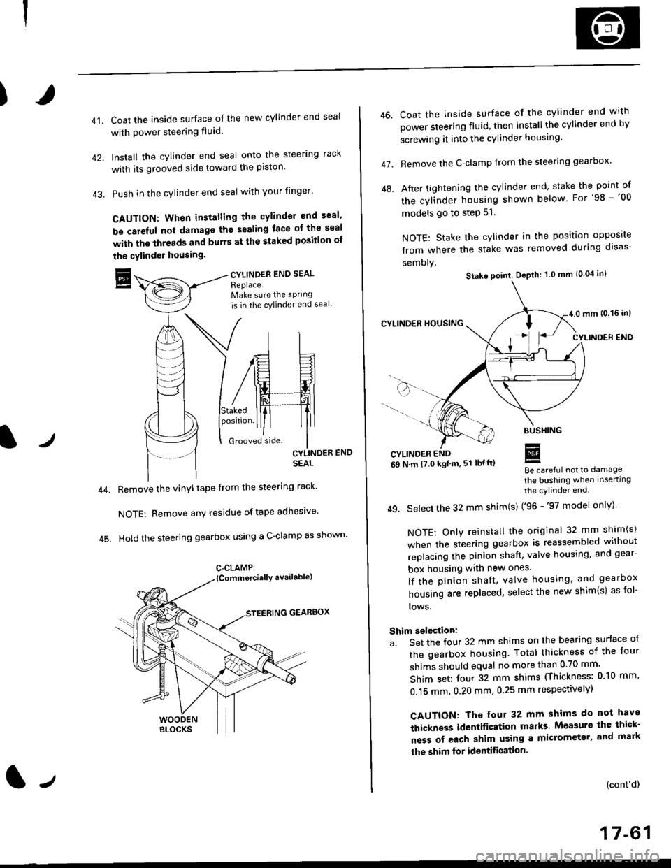
41.Coat the inside surface of the new cylinder end seal
with power steering fluid.
Install the cylinder end seal onto the steering rack
with its grooved side toward the piston'
Push in the cylinder end seal with your finger'
CAUTION: When installing the cylinder end sesl'
be carelul not damage the sealing face ot the seal
with the threads and burrs at the staked position oI
the cylinder housing.
trCYLINDES END SEAL
Replace.Make sure the sPring
is in the cylincler end seal
CYLINDER END
SEAL
Remove the vinyl tape from the steering rack'
NOTE: Remove any residue oftape adhesive
Hold the steering gearbox using a C-clamp as shown'
GEARBOX
C-CLAMP:
l-,
46.
47.
Coat the inside surface of the cylinder end with
power steering fluid, then installthe cylinder end by
screwing it into the cylinder housang.
Remove the C-clamp from the steering gearbox'
After tightening the cylinder end' stake the point of
the cylinder housing shown below For'98 -'00
models go to step 51.
NOTE: Stake the cylinder in the position opposite
from where the stake was removed during disas-
semoly.
Be careful not to damage
the bushing when inserting
the cylinder end.
49. Select the 32 mm shim(s) ('96 -'97 model only)'
NOTE: Only reinstall the original 32 mm shim(s)
when the steering gearbox is reassembled without
replacing the pinion shatt, valve housing, and gear
box housing with new ones.
lf the pinion shaft, valve housing, and gearbox
housing are replaced, select the new shim{s) as fol-
lows.
Shim selection:
a. Set the four 32 mm shims on the bearing surface of
the gearbox housing. Total thickness of the four
shims should equal no more than 0 70 mm'
Shim set: four 32 mm shims (Thickness: 010 mm'
0.15 mm, 0.20 mm, 0.25 mm respectivelyl
CAUTION: Th€ four 32 mm shims do not have
thickness identification marks Measure the thick-
ness of each shim using a micrometsr, and mark
the shim lor identification.
(cont'd)
17-61
Stake point. Depth: 1 0 mm (0.04 in)
Page 1118 of 2189
Steering Gearbox
Reassembly (cont'd)
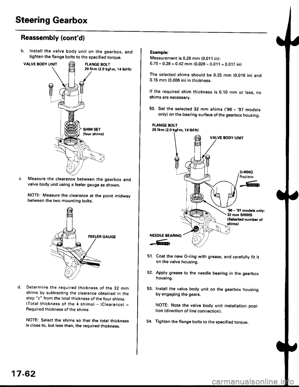
b. Install the valve body unit on the gearbox, andtighten the flange bolts to the specified torque.
VALVE BODY UNTTFLANGE BOLT20 N.m {2.0 ksl.m, 14lbI.ftl
Measure the clearance between the gearbox andvalve body unit using a feeler gauge as shown.
NOTE: Measure the clearance at the point midwaybetween the two mounting bolts.
Determine the required thickness of the 32 mmshims by subtracting the clearance obtained in thestep "c" from the total thickness of the four shims.(Total thickness of the 4 shims) - (Clearance) =
Required thickness of the shims
NOTE: Select the shims so that the total thicknessis close to. but less than, the required thickness,
17-62
54.
Example:
Measurement is 0.28 mm (0.011 in):0.70 - O.28 = 0.42 mm (0.028 - 0.011 = O.Ot7 inl
The selected shims should be 0.28 mm lO.OtO in) and0.15 mm {0.006 in} in thickness.
lf the r€quired shim thickness is 0.10 mm or less, noshims are necessarv.
50. Sot the selected 32 mm shims (,96 - ,97 modelsonly) on the bearing surface ofthe gearbox housing.
FLANGE BOLT20 N.m 12.0 ksf.m, 1l lbtftl
VALVE BODY UNIT
'96 - 37 modsl3 only:32 mm SHIMS{S.loctod numb.r of3him!l
Coat ths new O-ring with grease, and carefully fit iton the valve housing.
Apply grease to the needle bearing in the gearboxhousing.
Install the valve body unit on the gearbox housingby engaging the g€ars.
NOTE: Note the valve body unit installation posi-
tion (direction of line connection).
Tighten the flange bolts to the specified torque.
O-RINGReplace.
-A-l
NEEDLE BEARING
-R1
51.
EA
Page 1119 of 2189
)
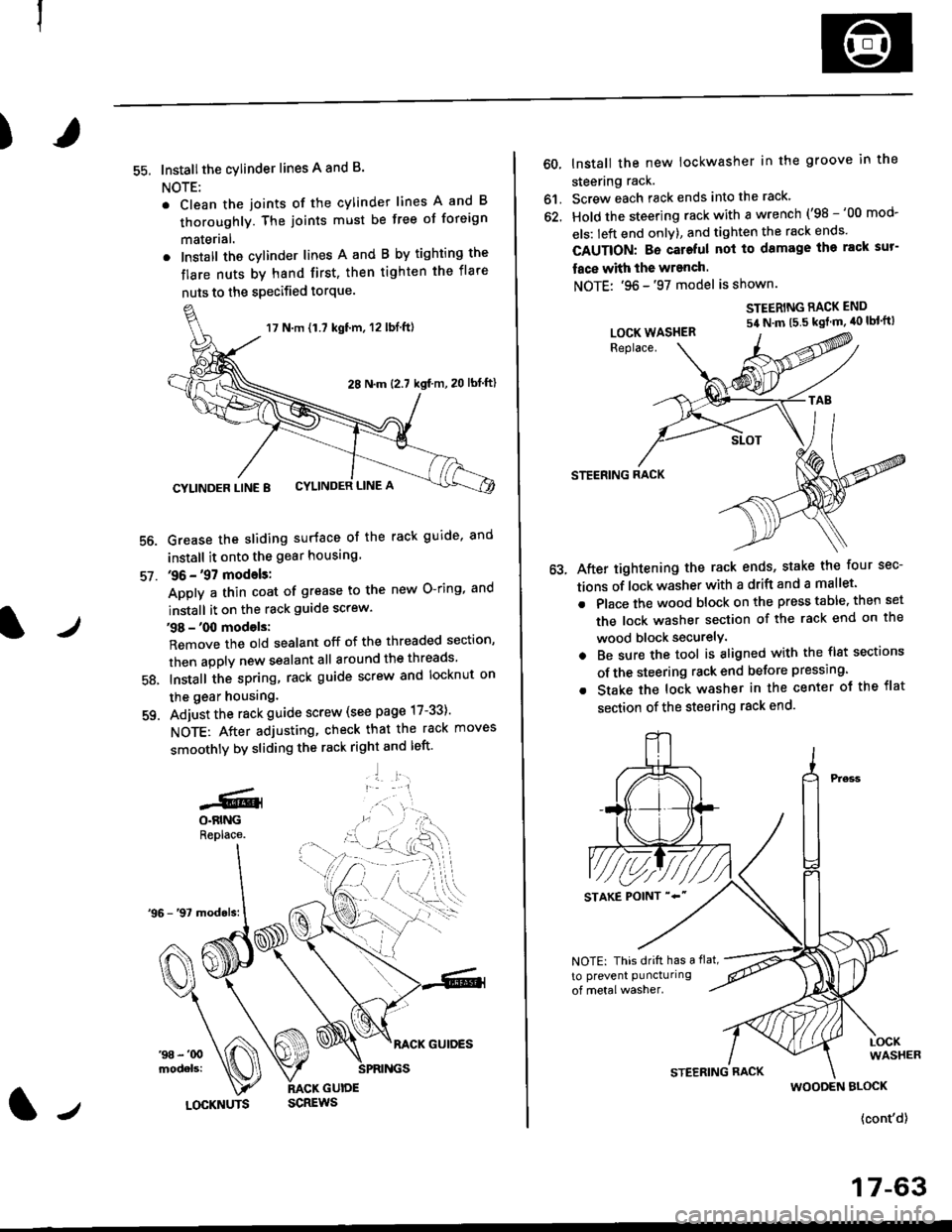
55. Installthe cylinder lines A and B.
NOTE:
. Clean the joints of the cylinder lines A and B
thoroughly. The joints must be free of foreign
materlal.
. Install the cylinder lines A and B by tighting the
flare nuts by hand first, then tighten the flare
nuts to the specified torque.
56.
57.
Grease the sliding surface of the rack guide, and
install it onto the gear housing
36 - '97 models:
Apply a thin coat of grease to the new O-ring, and
install it on the rack guide screw.
38 - '00 models:
Remove the old sealant off of the threaded section,
then apply new sealant all around the threads
Install the spring, rack guide screw and locknut on
the gear housing.
Adjust the rack guide screw (see page 17-33)'
NOTE: After adjusting, check that the rack moves
smoothly by sliding the rack right and left'
'1 l:.r1
58.
-GlO.BINGReplace.
17 N.m {1.7 kgt'm, 12 lbl.ft)
28 N.m (2.7 kgf m,20 lbf ftl
CYLINDER LINE 8 CYLINDER LINE A
l/LOCKNUTS
60, lnstall the new lockwasher in the groove in the
steering rack.
61. Screw each rack ends into the rack'
62. Hold the steering rack with a wrench ('98 -'00 mod-
els: left end onlY), and tighten the rack ends'
CAUTION: Bo cateful nol to damage ihe rack sur-
face with the wranch.
NOTE: '96 -'97 model is shown.
STEERING RACK END
54 N'm t5 5 kgt m' 40 lbl'ft)
STEERING RACK
After tightening the rack ends, stake the four sec-
tions of lock washer with a drift and a mallet.
Place the wood block on the press table. then set
the lock washer section of the rack end on the
wood block securelY.
Be sure the tool is aligned with the flst sections
of the steering rack end belore pressing.
Stake the lock washer in the center ot the flat
section of the steering rack end.
LOCK WASHER
NOTE: This drift has a flat,
to prevent puncturing
WOODEN BLOCK
{cont'd}
17-63
Page 1120 of 2189
Steering Gearbox
Reassembly (cont'dl
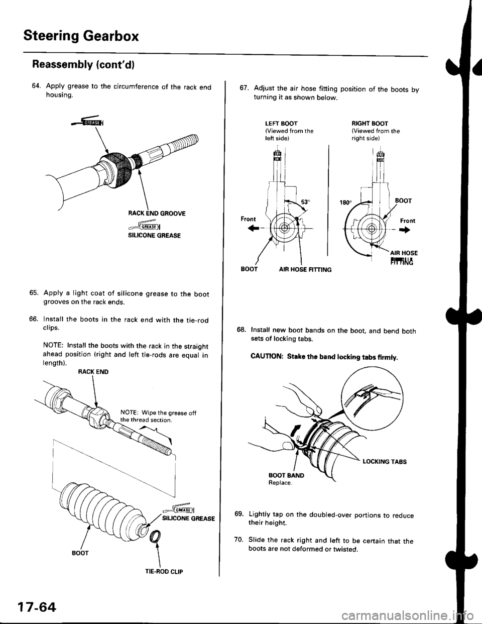
64. Apply grease to the circumference of the rack endhousing.
RACK END GROOVE
=^.#-q!:s!!H
SILICONE GREASE
Apply a light coat of silicone grease to the bootgrooves on the rack ends.
lnstall the boots in the rack end with the tie-rodclips.
NOTE: Install the boots with the rack in the straightahead position (right and left tie-rods are equal inlength).
66.
RACK END
NOTE: Wipe the grease offthe thread section.
17-64
TIE.ROD CLIP
67. Adjust the air hose fitting position of the boots bvturning it as shown below.
LEFT BOOT(Viewed from theleft side)
RIGHT BOOT{Viewed from theright side)
AIR HOSE FITTING
Install new boot bands on the boot, and bend bothsets of locking tabs.
CAUTION: Stlke ths band locking tabs firmly.
Lightly tap on the doubled-over portions to reducetheir height.
Slide the rack right and left to be certain that theboots are not deformed or twisted.