1999 HONDA CIVIC cv joint
[x] Cancel search: cv jointPage 1141 of 2189
Front Damper
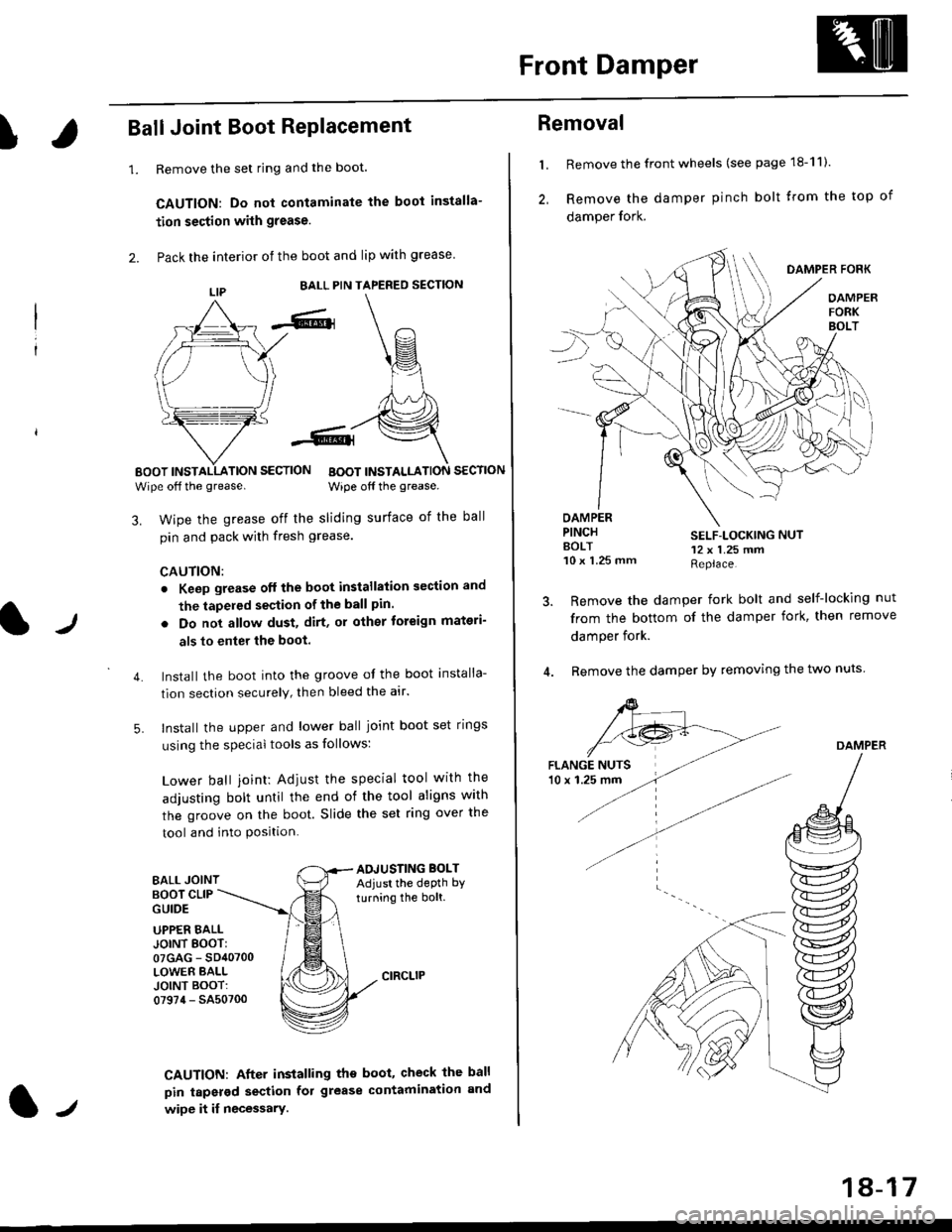
!Ball Joint Boot RePlacement
1.Remove the set ring and the boot.
CAUTION: Do not contaminate the boot installa-
tion section with grease.
Pack the interior of the boot and lip with grease
EALL PIN TAPERED SECTION
EOOT INSTALLATION SECTION
Wipe off the grease.BOOT INSTALLATION SECTION
Wipe off the grease.
lJ
3. Wipe the grease off the sliding surface of the ball
pin and pack with fresh grease.
CAUTION:
. Keep grease off the boot installation section and
the tapeled section of the ball pin.
5.
. Do not allow dust, dirt, or other toreign materi-
als to enter the boot.
Install the boot into the groove of the boot installa-
tion section securely, then bleed the atr.
Install the upper and lower ball joint boot set rings
using the special tools as follows:
Lower ball joint: Adiust the special tool with the
adjusting bolt until the end of the tool aligns with
the groove on the boot. Slide the set ring over the
tool and into Position.
BALL JOINTAOJUSTING BOLTAdjust the depth by
turning the bolt.BOOT CLIPGUIDE
4.
UPPER EALLJOINT EOOT:07GAG - SD40700LOWER BALLJOINT BOOT:07974 - SA50700
CAUTION: After installing the boot, check the ball
pin tapsrod section fol grease contamination and
wipe it if necessary.lt
18-17
Removal
l. Remove the front wheels (see page 18-11).
2, Remove the damper pinch bolt trom the top of
damper fork.
DAMPER FORK
OAMPERFORKBOLT
OAMPERPINCHAOLT10 x 1.25 mm
SELF-LOCKING NUT12 x 1.25 mmReplace.
Remove the damper fork bolt and self-locking nut
from the bottom of the damper fork, then remove
damper fork.
Remove the damper by removing the two nuts
DAMPER
Page 1146 of 2189
Rear Suspension
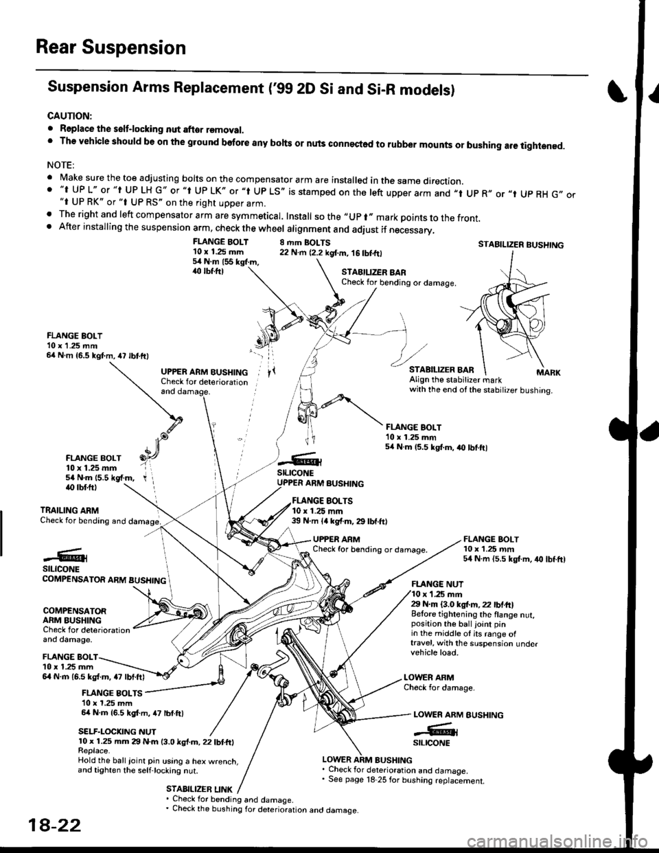
Suspension Arms Replacement ('gg 2D Si and Si-R models)
CAUTION:
. Roplace the self-locking nut after removal.' The vehicle should be on the gtound before any bohs or nuls connected to rubber mounts or bushing are tightened.
NOTE:
' Make sure the toe adjusting borts on the compensator arm are insta|ed in the same direction.. "t UP L" or "t UP LH G" or "t Up LK" or "l Up LS,, is stamped on the left upper arm and ,,t Up R,, or "t Up RH G,,"i UP RK" or "t UP RS" on the right upper arm.. The right and left compensator arm are symmeticar. Install sothe"upr"markpointstothefront.. After installing the suspension arm, check the wheel atignment and adiust if necessary,
FLANGE BOLT'10 x 1.25 mm54Nm155kgl.m,,rc lbf.ftl
8 rhm BOLTS22 N.m {2.2 kgf.m, 16 tbtfrlSTABILIZER BUSHTNG
FLANGE BOLT10 x 1.25 rnm54 N.m {5.5 kgt m, iro lbf.ft)
STAEILIZER BARCheck for bending or damage.
FLANGE BOLT10 x 1 .25 mm64 N m {5.5 kgf.m,47 lbtftl
FLANGE BOLT10 x 1.25 mm54 N.m 15.5 *gf.m,
and
UPPER ARM BUSHINGCheck for deteriorationAlign the stabitizer markwith the end ot the stabilizer bushing.
FLANGE BOLT'10 x 1.25 mm54 N.m 15.5 kgt.m, a0 lbtftl
stLrcoNEUPPER ARM BUSHINGiO lbf.ftl
TRAILING ARMCheck for bending and
EOLTS10 x 1.25 mm39 N m ll kgf.m, 29 lbf.ft)
UPPER ARMCheck for b€nding or damage.#@lstLtcoNECOMPENSATOR ARM BUSHING
COMPENSATORARM BUSHINGCheck for deteriorationand damage.
FLANGE NUTr '1.25 mm29 N.m {3.0 ksl.m,22 lbtft}Belore tightening the flange nut,position the ball joint pinin the middle ol its range oftravel, with the suspension undervehicle load.
LOWER ARMCheck for damage-
BUSHING
FLANGE BOLTl0 x 1.25 mm6l N.m 16.5 kg{.m, a7 lbt.ftl
FLANGE BOLTS10 x 1,25 mm64 N.m {6.5 kgf.m, 47 lbf.ftl
SELF.LOCKNG NUT
LOWER ARM
-GrstltcoNE10 x 1.25 mm 29 N.m (3.0 ksl.m, 22 tbtfrlReplace.Hold the ball ioinl pin using a hex w.enct.and tighten the selfjocking nut.
STABILIZEB LINK
LOWER ARM BUSHING. Check for deterioration and damaoe.' See page 18 25 for bushing replaciement.
' Check for bending and damage.. Check the bushing for deterioration ano oamage.
18-22
Page 1163 of 2189
)
It
7. Clean the caliper thoroughly; remove any rust, and
check for grooves and cracks.
8. Check the brake disc for damage and cracks.
9. lnstall the pad retainers,
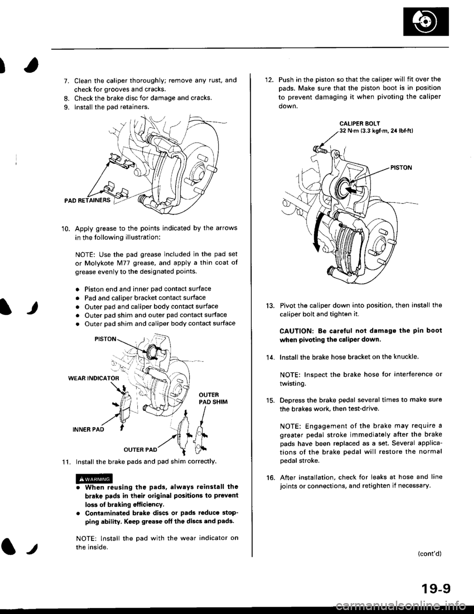
10. Apply grease to the points indicated by the arrows
in the following illustration:
NOTE: Use the pad grease included in the pad set
or Molykote Nl77 grease, and apply a thin coat of
grease evenly to the designated points.
o Piston end and inner Dad contact surface
. Pad and calioer bracket contact surface
. Outer pad and caliper body contact surface
. Outer pad shim and outer pad contact surface
. Outer pad shim and caliper body contact surface
WEAR INDICATOB
INNER PAD
OUTER PAD
1 1. Install the brake pads and pad shim correctly.
. Whon reusing the pads, always reinstall the
brake pads in their original positions to prevont
loss of braking efticiency.
. Contaminated brake discs or pads teduce stop-
ping ability. Keep grease oft the discs and pads'
NOTE: lnstall the Dad with the wear indicator on
the inside.l.t
'12. Push in the piston so that the caliper will fitoverthe
pads, Make sure that the piston boot is in position
to prevent damaging it when pivoting the caliper
down.
Pivot the caliper down into position, then install the
caliper bolt and tighten it.
CAUTION: Be caretul not damage the pin boot
when pivoting the caliper dowr.
lnstall the brake hose bracket on the knuckle
NOTE: Inspect the brake hose for interference or
twisting.
Depress the brake pedal several times to make sure
the brakes work. then test-drive.
NOTE: Engagement of the brake may require a
greater pedal stroke immediately after the brake
pads have been replaced as a set. Several applica-
tions of the brake pedal will restore the normal
Dedal stroke.
After installation. check for leaks at hose and line
joints or connections, and retighten if necessary.
13.
14.
15.
16.
(cont'd)
19-9
CALIPER BOLTN m (3.3 kgf m,2a lbf.ft)
Page 1165 of 2189
)
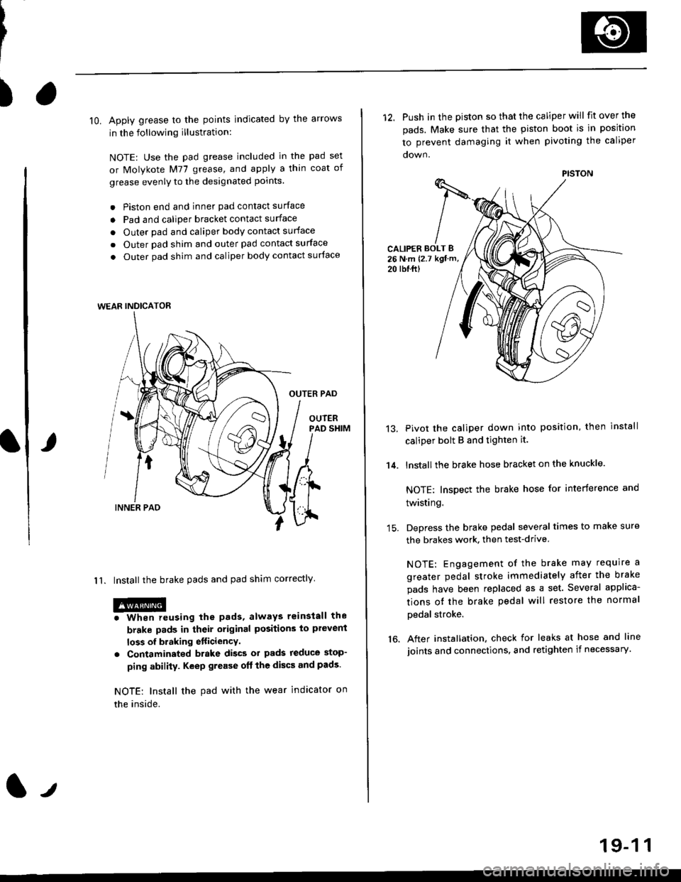
lO. Apply grease to the points indicated by the arrows
in the following illustration:
NOTE: Use the pad grease included in the pad set
or Molykote M77 grease, and apply a thin coat of
grease evenly to the designated points.
. Piston end and inner pad contact surface
o Pad and caliper bracket contact surface
. Outer pad and caliper body contact surface
. Outer pad shim and outer pad contact surface
. Outer pad shim and caliper body contact surface
OUTER PAD
OUIERPAD SHIM
I 1. Install the brake pads and pad shim correctly
@o When reusing the pads, always reinstall the
brake pads in their original positions to plevent
loss of braking etticiencY.
. Contaminated brake discs ol pads reduce stop-
ping ability. Keep grease oft the discs and pads.
NOTE: Install the pad with the wear indicator on
the inside.
WEAR INDICATOR
12. Push in the piston so that the caliper will fit over the
pads. Make sure that the piston boot is in position
to prevent damaging it when pivoting the caliper
CALIPER BOLT B26 N.m {2.7 kgt m,
20 rbl.ftl
14.
13.Pivot the caliper down into position, then install
caliper bolt B and tighten it.
lnstallthe brake hose bracket on the knuckle.
NOTE: Inspect the brake hose for interference and
twisting.
Depress the brake pedal several times to make sure
the brakes work, then test-drive
NOTE: Engagement of the brake may require a
greater pedal stroke immediately after the brake
pads have been replaced as a set. Several applica-
tions ot the brake pedal will restore the normal
pedal stroke.
After installation, check for leaks at hose and line
joints and connections, and retighten if necessary.16.
PISTON
19-1 1
Page 1171 of 2189
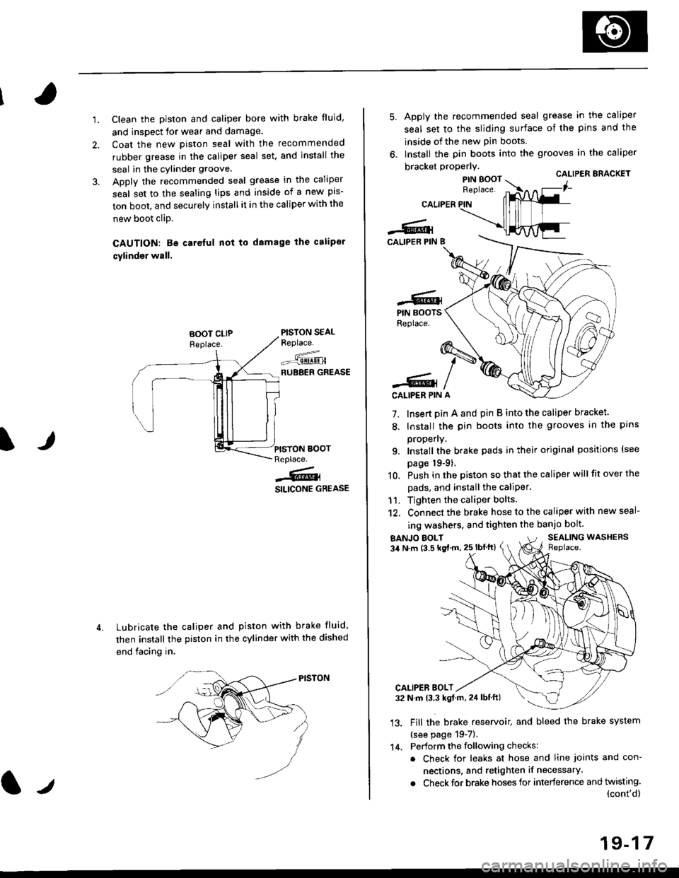
'1.Clean the piston and caliper bore with brake fluid,
and inspect for wear and damage.
Coat the new piston seal with the recommended
rubber grease in the caliper seal set. and install the
seal in the cylinder groove.
Apply the recommended seal grease in the caliper
seal set to the sealing lips and inside of a new pis-
ton boot, and securely install it in the caliper with the
new boot clip.
CAUTION: Be careful nol to damage the caliper
cylinder wall.
PISTON SEALReplace.
--^.,:=-qE!!!-HRUBBER GREASE
Lubricate the caliper and piston with brake fluid,
then install the piston in the cylinder with the dished
end facing in.
IJPISYON BOOTReplace.
j@i
SILICONE GREASE
CALIPER
-6lCALIPEB PIN B
Apply the recommended seal grease in the caliper
seal set to the sliding surface of the pins and the
lnside of the new pin boots.
lnstall the pin boots into the grooves in the caliper
bracket properly.CALIPER ERACKET
7. Insert pin A and pin B into the caliper bracket.
8. Install the pin boots into the grooves in the pans
propeny.
9. Install the brake pads in their original positions (see
page 19-9).
10. Push in the piston so that the caliper will fit over the
pads, and install the caliPer.
11. Tighten the caliper bolts.
12. Connect the brake hose to the caliper with new seal-
ing washers, and tighten the banjo bolt.
-6.lPIN BOOTSReplace.
-6lCALIPER PIN
BANJO EOLT34 N.m (3.5 kg{ m, 25 lbflt}SEALING WASHERSReplace.
'13.
CALIPER BOLT32 N.m 13.3 kgt.rn, 24lblft)
Fill the brake reservoit and bleed the brake system
{see page 19-7).
Perform the following checks:
. Check for leaks at hose and line joints and con-
nections. and retighten if necessary.
. Check for brake hoses for interference and twisting.(cont'd)
14.
19-17
Page 1179 of 2189
I
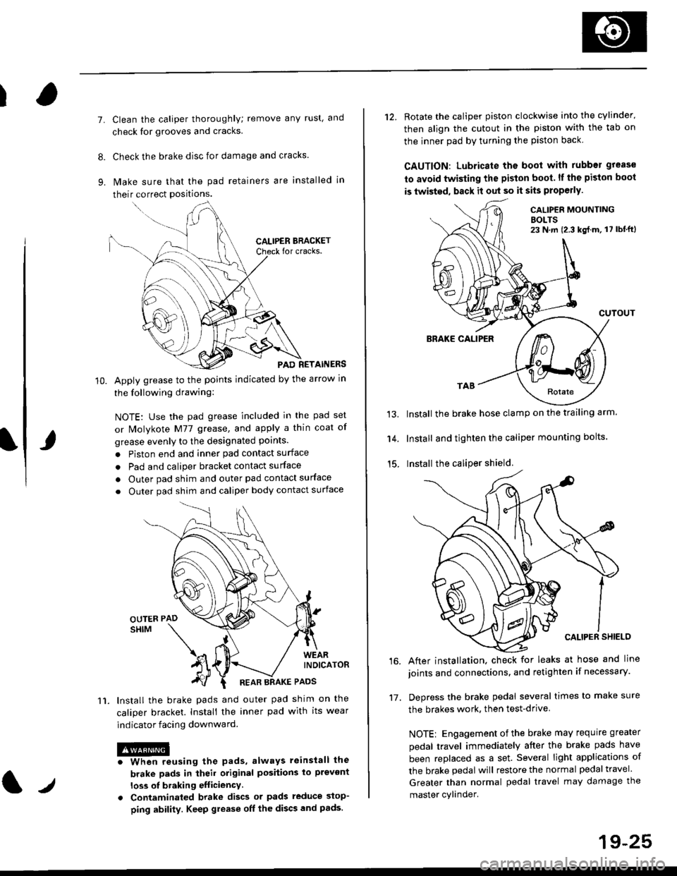
7.
11.
Clean the caliper thoroughly; remove any rust, and
check for grooves and cracks.
Check the brake disc for damage and cracks.
lvlake sure that the pad retainers are installed in
their correct positions.
PAD RETAINERS
Apply grease to the points indicated by the arrow in
the following drawing:
NOTE: Use the pad grease included in the pad set
or lMolykote M77 grease, and apply a thin coat of
grease evenly to the designated points.
. Piston end and inner pad contact surface
. Pad and caliper bracket contact surface
. Outer pad shim and outer pad contact surface
. Outer pad shim and caliper body contact surface
lnstall the brake pads and outer pad shim on the
caliper bracket. Install the inner pad with its wear
indicator facing downward.
@iwhen reusing the pads, always reinstall the
brake pads in iheil original posiiions lo prevont
loss ol braking efficiency
. Contaminaled brake discs or pads reduce stop-
ping ability. Keep grease off the discs and pads.
t./
19-25
12. Rotate the caliper piston clockwise into the cylinder'
then align the cutout in the piston with the tab on
the inner pad by turning the piston back
CAUTION: Lubricate ths boot with rubber grease
to avoid twisting the piston boot. lf the piston boot
is twisted, back it out so it sits properly.
CALIP€R MOUNTINGBOLTS23 N,m {2.3 kg{.m, 17 lbt'ft)
13.
14.
15.
CUTOUT
BRAKE CALIPER
Install the brake hose clamp on the trailing arm.
Install and tighten the caliper mounting bolts.
Install the caliper shield.
After installation. check for leaks at hose and line
joints and connections, and retighten if necessary.
Depress the brake pedal several times to make sure
the brakes work, then test-drive
NOTE: Engagement of the brake may requrre greater
pedal travel immediately after the brake pads have
been replaced as a set. Several light applications of
the brake pedal will restore the normal pedal travel.
Greater than normal pedal travel may damage the
master cylinder.
16.
17.
Page 1188 of 2189
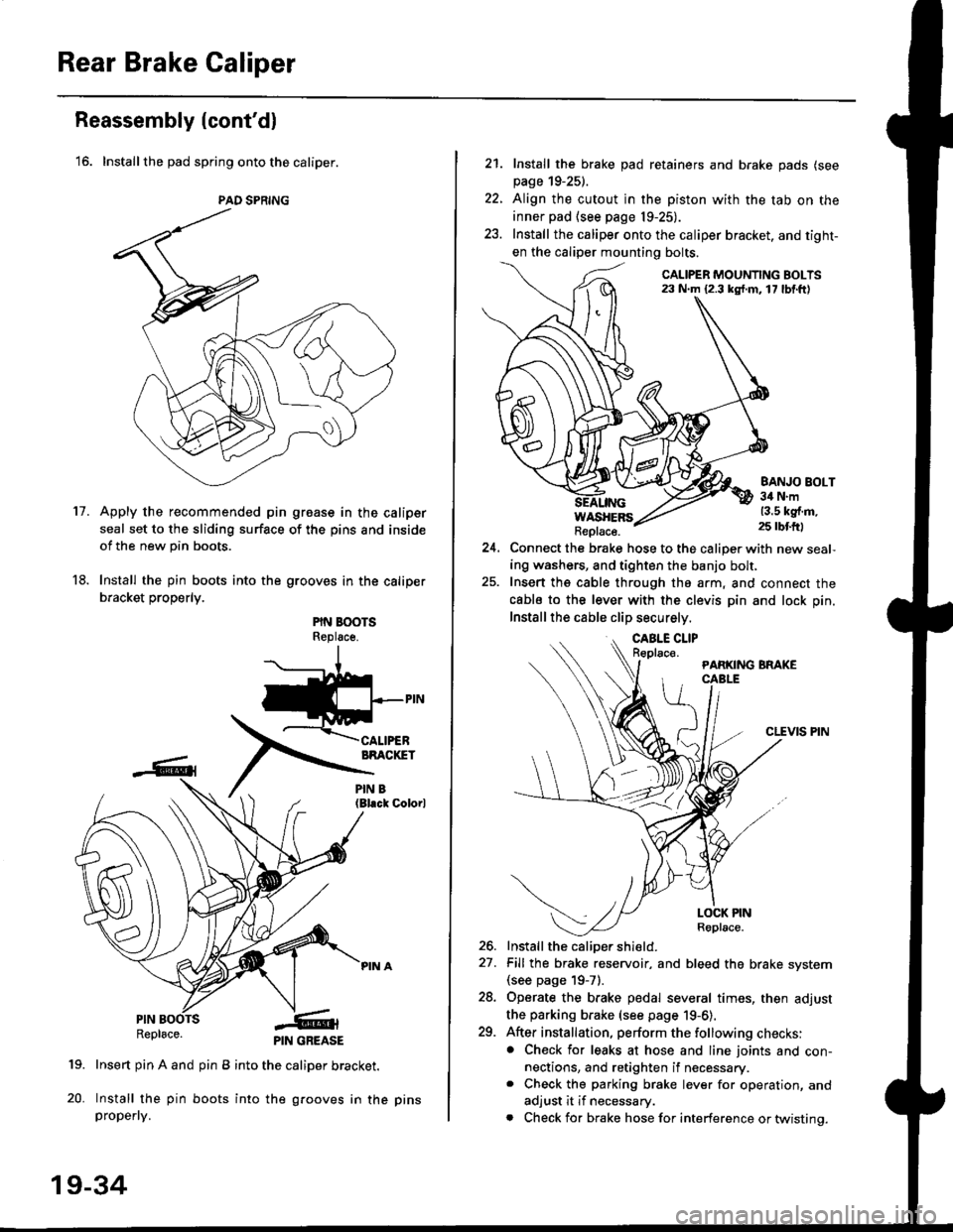
Rear Brake Caliper
Reassembly (cont'dl
'16. Installthe pad spring onto the caliper.
Apply the recommended pin groase in the caliper
seal set to the sliding surface of the pins and inside
of the new pin boots.
Install the pin boots into the grooves in the caliper
bracket properly.
PIN BOOTSReplsce.
(Bl.ck Colorl
PINRepl6ce.
19. Insert pin A and pin B into the caliper bracket.
20. Install the pin boots into the grooves in thepropefly.
PAD SPRING
11.
PIN GREASE
19-34
pr ns
22.
21. Install the brake pad retainers and brake pads (see
page 19-25).
Align the cutout in the piston with the tab on the
inner pad (see page 19-25).
Install the caliper onto the caliper bracket. and tight-
en the caliper mounting bolts.
CALIPER MOUNTING BOLTS23 N.m {2.3 kg{.m. 17 lbf.ft)
WASHERSReplace.
BANJO BOLT34 N.m13.5 kg{.m.25 rbtft)
24.Connect the brake hose to the caliper with new seal,
ing washers, and tighten the banjo bolt,
Insert ths cable through the arm, and connect the
cabls to the lever with the clevis pin and lock pin.
Install the cable clip securely.
CLEVIS PIN
-t
//t
LOCK PINRoplace.
26. Install the caliDer shield.
27. Fill the brake reservoir, and bleed the brake svstem(see page 19-71.
28. Operate the brake pedal several times, then adjust
the parking brake (see page 19-6).
29. After installation, perform the following checks:. Check for leaks at hose and line joints and con-nections, and retighten if necessary.. Check the parking brake lever for operation, and
adjust it if necessary.
. Check for brake hose for interference or twistinq.
Page 1194 of 2189
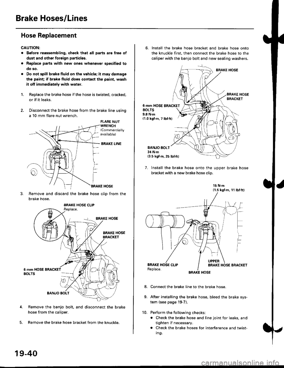
Brake Hoses/Lines
Hose Replacement
CAUTION:
. Bgfore reagsembling, chgck that all parts are free of
dust and othor foroign particles.
. Repl8ce parts with new ones whenever specified to
do so,
. Do not spill brake fluid on th6 vehicle; it may damage
tho paint; if brake fluid does contact the paint, wash
it off immediately with water.
1.Replace the brake hose if the hose is twisted, cracked,
or if it leaks.
Disconnect the brake hose from the brake line using
a 10 mm flare nut wrench.
FLARE NUTWRENCHlCommerciallyava ilable)
BRAKE LINE
BRAKE HOSE
Remove and discard the brake hose cliD from the
brake hose.
Remove the banjo bolt, and disconnect the brake
hose from the caliper.
Remove the brake hose bracket from the knuckle.
19-40
10.
6. Install the brake hose bracket and brake hose onto
the knuckle first. then connect the brake hose to the
caliper with the banjo bolt and new sealing washers.
BRAKE HOSE
6 mm HOSE BRACKETBOLTS9.8 N.m{1.0 kgf m, 7 lbtfr}
BANJO BOI.T34 N.m{3.5 kgf.m,25 lbt.ftl
7. Install the brake hose onto the uooer brake hose
bracket with a new brake hose clip
15 N.m(1.s ks{.m, 11 lbl.ftl
Connect the brake line to the brake hose.
After installing the brake hose, bleed the brake sys-
tem (see page 19-7).
Perform the following checks:
. Check the brake hose and line joint for leaks, and
tighten if necessary.
. Check the brake hoses for interference and twist-
I ng.
8.