Page 1235 of 2189
\:Outer Handle Replacement
NOTE: Raise the glass fully.
'1. Remove:
. Door panel
. Plastic cover (see page 2o-21
2. Pull out the retainer cliP.
6x1.omm Ii.e N.. tr.o rgf.-, I7.2 rbr.fi) ,2
C3.
CYLINDER PROTECTOR
LOCK CYLINDEB
RETAINERCLIP
Remove the bolts, then remove the cylinder protec-
tor, lock cylinder and outer handle.
>: Bolt locaiions,2
CYLINDER
LOCK CYLINDER
CYLINDER ROD
20-5
4. Pull out the outer handle. Pry the outer handle rod
out of its joint using diagonal cutters
NOTE:
a To ease reassembly, note location @ of the outer
handle rod on the joint before disconnecting it.
. Take care not to bend the outer handle rod.
o Use a shop towel to protect the opening in the
ooor.
OUTER HANDLEROD
DIAGONALCUTTERS
SHOPTOWEL
lnstallation is the reverse of the removal procedure
NOTE: Make sure the door locks and opens properly.
BUSHINGReplace.
\
,w.
5.
i4'
Page 1241 of 2189
tOuter Handle Replacement
NOTE: Raise the glass fullY.
1. Remove:
. Door panel
. Plastic cover (see page 20-8)
2. Remove the screws.
>: Screw locations, 3
6x1.0mm6 N.m {0.6 kgf m,4 tbf.ftl
a\
3. Move the latch down, and remove the bolts.
>: Bolt locations,2
6x1.0mm9.8 N,m )11.O kst.n,7.2lbiftl //
4. Pull out the outer handle. Pry the outer handle rod
out of its joint using diagonal cutters.
NOTE:
. To ease reassembly, note location O of the outer
handle rod on the joint before disconnecting it.
. Take care not to bend the outer handle rod.
. Use a shop towel to protect the opening in the
door.
BUSHINGReplace.
OUTERHANDLEROD
5.
o
DIAGONAL \
:"'* ,w,
lnstallation is the reverse of the removal procedure
NOTE: N4ake sure the door locks and opens properly.
SHOP TOWEL
20-11
Page 1247 of 2189
bOuter Handle Replacement
NOTE: Raise the glass fully.
1. Remove:
. Door panel
. Plastic cover (see page 20-14)
2. Pull out the retainer clip.
3.e\
CYLINOER PROTECTOR
LOCK CYLINDER
RETAINERCLIP
Remove the bolts, then remove the cylinder protec-
tor, lock cylinder and outer handle.
>: Bolt locations,2
6x1.omm ]9.8 N.m {1.0 kgf.m,1.2tbl,ttl )_, _-_-,/
CYLINDERPROTECTOR
LOCK CYLINOER
CYLINOER ROD
20-17
4. Pull out the outer handle. Pry the outer handle rod
out of its joint using diagonal cutters.
NOTE:
. To ease reassembly, note location @ ot the outer
handle rod on the joint before disconnecting it.
. Take care not to bend the outer handle rod.
. Use a shop towel to protect the opening in the
door.
DIAGONALCUTTERS
SHOPTOWEL
5. Installation is the reverse of the removal procedure.
NOTE: Make sure the door locks and opens properly.
EUSHINGReplace.
\
,pr,
Page 1255 of 2189
|}Mirror Holder/Cover Replacement
CAUTION: Put on gloves to protecl your hands.
L Carefully pry out the mirror holder with a flat tip
screwdriver as shown.
Installation is the reverse of the removal procedure.
NOTE: Apply grease to the locations indicated by
the arrows.
>: Sc.ew locationsA >, 3 s>,2
I
ry
To remove the screws,pull the seal away.
PIVOT
-6rJOINT PIN
-G{
J
6)drD
)
I
SHOP TOWEL
Rearview Mirror Replacement
1. Remove the rubber damper.
2. Pry the cover off using the end of a flat tip screw-
drivef.
CAUTION: When prying with a flat-tip screwdriver,
wrap it with a shop towel to prgvant damage.
3. Remove the screws, then remove the rearview mir-
ror,
4. Installation is the reverse of the removal procedure.
SCREW5x0.8mmil N.m lo.a kgf.m,3 lbf.ftl
SHOP TOWEL
20-25
Page 1295 of 2189

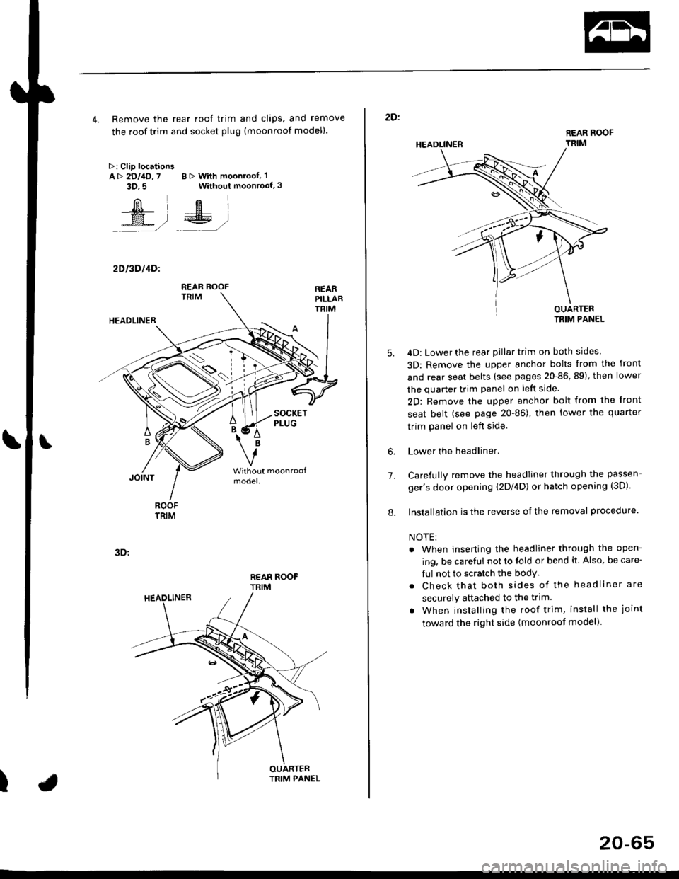
4. Remove the rear roof trim and clips, and remove
the roof trim and socket plug (moonroof model).
>: Clip locationsA> 2DllD,7 B > With moonroof, 'l
3D.5 Without moonroof,3
[il',fEl
t% .l €E .l':: =,/ _._- ,/
2D l3D l4Dl
REAR ROOFTRIM
3D:
t
REAR ROOF
TRIM
2D:
5.
7.
OUARTERIRIM PANEL
4D: Lower the rear pillar trim on both sides
3D: Remove the upper anchor bolts from the front
and rear seat belts (see pages 20-86, 89), then lower
the quarter trim panel on left side.
2D: Remove the upper anchor bolt from the front
seat belt (see page 20-86), then lower the quaner
trim panel on left side.
Lower the headliner.
Carefully remove the headliner through the passen-
ger's door opening (2Dl4D) or hatch opening (3D).
Installation is the reverse of the removal procedure.
NOTE:
. When inserting the headliner through the open-
ing, be careful not to fold or bend it. Also, be care-
ful not to scratch the bodY.
. Check that both sides of the headliner are
securely attached to the trim.
. When installing the roof trim, install the joint
toward the right side (moonroot model)
6.
8.
20-65
Page 1362 of 2189
4. Note the position of the ioint on the handle rod (A)'
Prv the handle rod ol the joint using diagonal cut-
ters; take care not to bend the rod Remove the
hatch handle.
BUSHINGReplace.
lnstall in the reverse order of removal, and note
these items:
Make sure
the handle rod is connected properly
Before installing the hatch trim panel, make sure
the hatch opens ProPerlY.
@
Hatch Latch/Lock CYlinder
Replacement
1.
2.
Remove the hatch trim panel (see page 20-63)'
Remove the hatch latch screws
>: Screw locations,3
6x1,0mm9.8 N.m 11.0 kgf'm,
7.2 tbt f0
HATCHLATCH
Disconnect the lock rod, the handle rod, the lock
cylinder rod. and the connector, then remove the
hatch latch.
LOCK CYLINDERROD
''---tCONNECTOR
HANDLEROD
(cont'd)
20-133
Page 1429 of 2189

Description
Outline
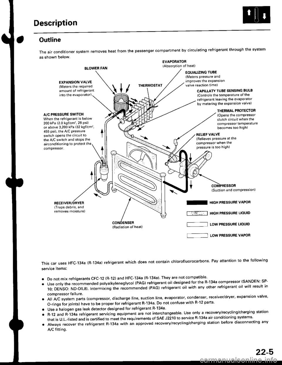
The air conditioner system removes heat from the passenger compartment by circulating refrigerant through the system
as shown below.
BLOWER FAN
EVAPORATOR(Absorption of heati
EOUALIZING TUBE(Meters pressure andimproves the expansionvalve reaction time)
into the evaporator)CAPILLATY TUBE SENSING BULB
lControls the temPerature of the
ref rigerant leaving the evaporator
by metering the expansion valve)
/\
THERMOSTAT
A/C PRESSURE SWITCH
When the refrigerant is below
200 kPa (2.0 kgtcm'�,28 Psi)or above 3,200 kPa 132 kgflcm',
455 psi), the Ay'C pressure
switch opens the circuit to
the A,/C switch and stops the
EXPANSION VALVE(Meters the requiredamount of refrigerant
airconditioning to Protect the
compressor.
RECEIVER/DRYER(Traps debris, andremoves morsturel
THERMAL PROTECTOR
{Opens the comPressorclutch circuit when the
compressor temPeraturebecomes too high)
RELIEF VALVE(Relieves pressure at the
compressor when thepressure is too high)
(Radiation of heat)
I
f-r-�-; I
(Suction and comPression,
HIGH PRESSURE VAPOR
HtGH PRESSUBE LIOUID
LOW PRESSURE LIOUID
This car uses HFC-134a (R-134a) refrigerant which does not contain chlorofluorocarbons Pay attention to the following
service items:
. Do not mix refrigerants CFC-12 (R-12) and HFC-134a (R-134a)' They are not compatible'
. Useonlythe recommended polyalkyieneglycol (PAG) refrigerant oil designedforthe R-134a compressor (SANDEN: SP-
10; DENSO: ND_OIL8). Intermixing ihe re-commended (pAG) refrigerant oil with any other refrigerant oil will result in
compressor failure.
. All A,,ic system parts {compressor, discharge line, suction line, evaporator, condenser, receiver/dryer, expansion valve'
O-rings for joints) have to be proper for refrigerant R- 134a Do not confuse with R-l2 parts'
. Use a halogen gas leak detector designed for refrigerant R-134a
. R-12 and R-134a refrigerant servacing equipment are not interchangeable. Use only a recovery/recycling/charging station
that is u,L.-listed and is certified to meet the requirements of sAE J2210 to service R-134a air conditioning systems'
. Always recover the refrigerant R-134a with an approved recovery/recycling/charging station before disconnecting any
A,/C fitting.
S]
22-5
Page 1450 of 2189

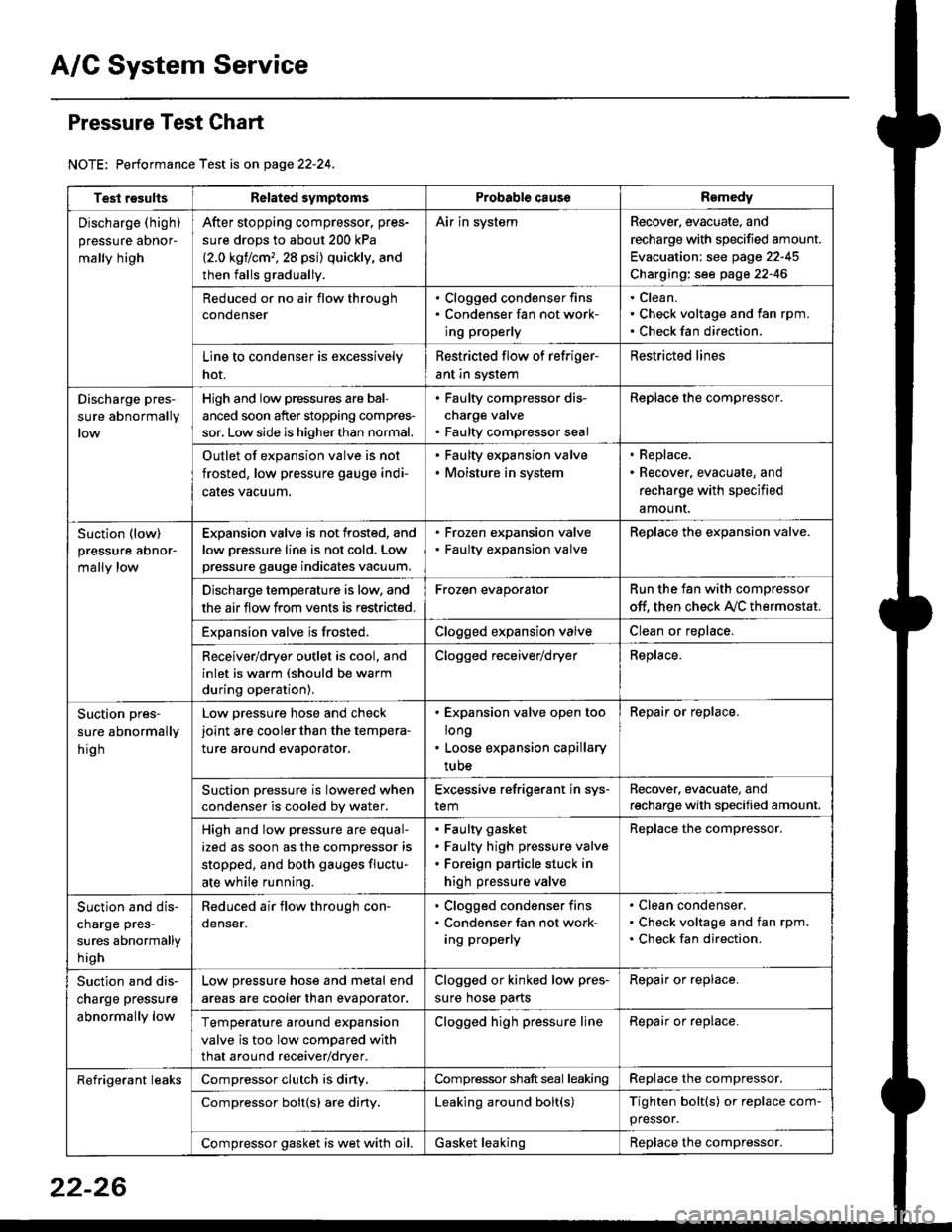
A/C System Service
Pressure Test Chart
NOTE: Performance Test is on page 22-24,
Test resultsRelated symptomsProbabl€ causeRemedy
Discharge (high)
pressure aDnor-
mally high
After stopping compressor. pres-
sure drops to about 200 kPa
{2.0 kgflcm,,28 psi) quickly, and
then falls gradually.
Air in systemRecover, evacuate, and
recharge with specified amount.
Evacuation: see page 22-45
Charging: see page 22-46
Reduced or no air flow through
condenser
. Clogged condenser fins. Condenser fan not work-
ing properly
Clean.
Check voltage and fan rpm.
Check fan direction.
Line to condenser is excessively
hot.
Restricted flow of refriger-
ant in system
Restricted lines
Discharge pres-
sure abnormally
High and low pressures are bal-
anced soon after stopping compres-
sor, Low side is higher than normal.
. Faulty compressor dis-
charge valve. Faulty compressor seal
Replace the compressor.
Outlet of expansion valve is not
frosted, low pressure gauge indi-
cales vacuum.
. Faulty expansion valve. Moisture in system
. Replace,. Recover, evacuate, and
recharge with specified
amount.
Suction (low)
pressure abnor-
mally low
Expansion valve is not frosted, and
low oressure line is not cold. Low
pressure gauge indicates vacuum.
. Frozen expansion valve. Faulty expansion valve
ReDlace the exoansion valve.
Discharge temperature is low. and
the air flow from vents is restricted.
Frozen evaporatorRun the fan with compressor
off. then check A,/C thermostat.
Exoansion valve is frosted.Clogged expansion valveClean or replace.
Receiver/dryer outlet is cool, and
inlet is warm (should be warm
during operation).
Clogged receiver/dryerReplace.
Suction pres-
sure abnormally
hig h
Low pressure hose and check
joint are cooler than the tempera-
ture around evaporator.
. Expansion valve open too
long. Loose expansion capillary
tube
Repair or replace.
Suction oressure is lowered when
condenser is cooled bv water.
Excessive refrigerant in sys-
tem
Recover. evacuate, and
recharge with specified amount.
High and low pressure are equal-
ized as soon as the compressor is
stopped, and both gauges fluctu-
ate while running.
Faulty gasket
Faulty high pressure valve
Foreign particle stuck in
high pressure valve
Replace the compressor.
Suction and dis-
charge pres-
sures abnormally
h igh
Reduced air flow through con-
denser.
. Clogged condenser fins. Condenser fan not work-
ing properly
Clean condenser.
Check voltage and fan rpm.
Check fan direction.
Suction and dis-
charge pressure
abnormally low
Low pressure hose and metal end
areas are cooler than evaporator.
Clogged or kinked low pres-
sure hose parts
Repair or replace.
Temperature around expansion
valve is too low compared with
that around receiver/dryer.
Clogged high pressure lineRepair or replace.
Refrigerant leaksCompressor clutch is diny,Compressor shaft seal leakingReplace the compressor.
Compressor bolt{s) are diny.Leaking around bolt(s)Tighten bolt(s) or replace com-
pressor.
Compressor gasket is wet with oil.Gasket leakingReplace the compressor.
22-26