1999 DODGE RAM roof
[x] Cancel search: roofPage 851 of 1691

Starters
Generator .................................. Generators & Regulators
Engine Performance
Power Distribution
Generic Electronic Module (GEM) ............... Body Control Modules\
Electronic Suspension
Glow Plug Relay ................................. Engine Performance
Glow Plugs ...................................... Engine Performance
Grounds ........................................ Ground Distribution
Headlight Door Module .............................. Headlight Doors
Headlight Relay .................................. Headlight Systems
Daytime Running Lights
Headlights ....................................... Headlight Systems
Daytime Running Lights
Heated Oxygen Sensor(s) (HO2S) .................. Engine Performan\
ce
Heated Windshield Control Module ................ Heated Windshields
Height Sensor ................................ Electronic Suspension
Horns ..................................... Steering Column Switches
Horn Relay ................................ Steering Column Switches
Idle Air Control (IAC) Motor/Valve .............. Engine Performance\
Ignition Coil(s) ................................ Engine Performance\
Ignition Key Lock Cylinder ....................... Anti-Theft System
Ignition Module ................................. Engine Performance
Ignition Switch ................................. Power Distribution
Engine Performance
Generators & Regulators
Starters
Illuminated Entry Module .............. Illumination/Interior Lights
Illumination Lights ................... Illumination/Interior Lights
Impact Sensor ............................. Air Bag Restraint System
Inertia Fuel Shutoff Switch ..................... Engine Performance
Inhibit Relay ............................................. Starters
Instrument Cluster ........................ Analog Instrument Panels
Intake Air Temperature (IAT) Sensor ............. Engine Performance\
Interior Lights ....................... Illumination/Interior Lights
Interlock Switch .......................................... Starters
Junction Block .................................. Power Distribution
Keyless Entry Receiver ........................ Remote Keyless Entry
Key Reminder Switch ....................................... Starters
Knock Sensor .................................... Engine Performance
Lamp Control Module ................................ Exterior Lights
License Plate Lamp ................................. Exterior Lights
Lighting Control Module ................... Lighting Control Modules
Anti-Theft System
Daytime Running Lights
Headlight Systems
Lower Relay .................................. Power Convertible Top
Malfunction Indicator Light (MIL) ............... Engine Performance\
Instrument Panels
Manifold Absolute Pressure (MAP) Sensor ......... Engine Performance\
Mass Airflow (MAF) Sensor ....................... Engine Performance\
Mega Fuse .................................. Generators & Regulators
Memory Seat/Mirror Module ........................... Memory Systems
Mirror Defogger ............................... Rear Window Defogger
Moon Roof Motor .................................... Power Moon Roof
Moon Roof Relay .................................... Power Moon Roof
Multi-Function Control Module ...................... Warning Systems
Neutral Safety Switch ..................................... Starters
Oil Level Switch ................................ Engine Performance
Oil Pressure Switch/Sending Unit .......... Analog Instrument Panels
Engine Performance
Overhead Console .................................. Overhead Console
Oxygen Sensor(s) (O2S) .......................... Engine Performan\
ce
Page 852 of 1691

Parking Brake Switch ...................... Analog Instrument Panels
Park Lights ........................................ Exterior Lights
Park/Neutral Position Switch .............................. Starters
Engine Performance
Anti-Theft System
Body Control Module
Perimeter Lighting Control Relay ................... Exterior Lights
Power Amplifier ..................................... Power Antennas
Power Antenna Module ................................ Power Antennas
Power Antenna Motor ................................. Power Antennas
Power Distribution Center ....................... Power Distribution
Generators & Regulators
Starters
Power Door Lock Motors ............................ Power Door Locks
Power Mirror Motors .................................. Power Mirrors
Memory Systems
Power Sliding Door Controller .............. Power Sliding Side Door
Power Seat Motors ...................................... Power Seats
Memory Systems
Power Steering Pressure Switch .................. Engine Performance
Power Top Motor .............................. Power Convertible Top
Power Top Relay(s) ........................... Power Convertible Top\
Powertrain Control Module ....................... Engine Performance
Analog Instrument Panels
Cruise Control Systems
Data Link Connectors
Generators & Regulators
Starters
Power Window Motors .................................. Power Windows
Power Window Relay(s) ................................ Power Windows\
Radiator Fan Motor(s) ........................ Electric Cooling Fans\
Radiator Fan Relay(s) ........................... Engine Performance\
Electric Cooling Fans
Rainsense Module .............................. Wiper/Washer Systems
Raise Relay .................................. Power Convertible Top
Remote Anti-Theft Personality (RAP) Module ....... Anti-Theft System\
Starters
Warning Systems
Seat Belt Pretensioners ................... Air Bag Restraint System
Seat Belt Retractor Solenoid .................... Passive Restraints
Seat Belt Switch .......................... Air Bag Restraint System
Passive Restraints
Shift Interlock Solenoid ................... Shift Interlock Systems
Shift Lock Actuator ........................ Shift Interlock Systems
Side Marker Lights ................................. Exterior Lights
SIR Coil Assembly (Clockspring) ........... Air Bag Restraint System\
Slip Ring (Clockspring) ................... Air Bag Restraint System\
Steering Column Switches
SRS Control Module ........................ Air Bag Restraint System
Starter Motor ............................................. Starters
Starter Interrupt Relay ................................... Starters
Starter Solenoid .......................................... Starters
Starter Relay ............................................. Starters
Steering Wheel Position Sensor .................... Anti-Lock Brakes
Stoplights ......................................... Exterior Lights
Stoplight Switch ................................ Engine Performance
Cruise Control Systems
Anti-Lock Brakes
Sun Roof ECU ........................................ Power Sun Roof
Sun Roof Motor ...................................... Power Sun Roof
Sun Roof Position Sensor ............................ Power Sun Roof
Taillights ......................................... Exterior Lights
Throttle Position (TP) Sensor ................... Engine Performance\
Page 1237 of 1691

operation involving steering column components. See
appropriate AIR BAG RESTRAINT SYSTEMS article. DO NOT apply
electrical power to any component on steering column without
first deactivating air bag system. Air bag may deploy.
CAUTION: When battery is disconnected, vehicle computer and memory
systems may lose memory data. Driveability problems may exist
until computer systems have completed a relearn cycle. See
COMPUTER RELEARN PROCEDURES article in GENERAL INFORMATION
before disconnecting battery.
HORN SWITCH
NOTE: Horn switch removal and installation information for Dakota
and Durango is not provided by manufacturer.
Removal & Installation
Disconnect negative battery cable. Remove 4 air bag nuts from
back of steering wheel. Pull air bag module back far enough to
disconnect wiring connectors. Remove air bag module. To install,
reverse removal procedure. Tighten air bag nuts to 90-97 INCH lbs. (9-
11 N.m).
IGNITION SWITCH
CAUTION: DO NOT bump, jolt or hammer on steering shaft and gearshift
tube.
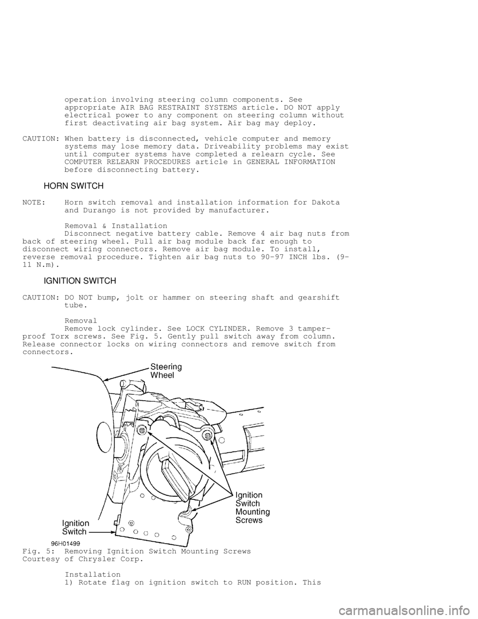
Removal
Remove lock cylinder. See LOCK CYLINDER. Remove 3 tamper-
proof Torx screws. See Fig. 5. Gently pull switch away from column.
Release connector locks on wiring connectors and remove switch from
connectors.
Fig. 5: Removing Ignition Switch Mounting Screws
Courtesy of Chrysler Corp.
Installation
1) Rotate flag on ignition switch to RUN position. This
Page 1240 of 1691

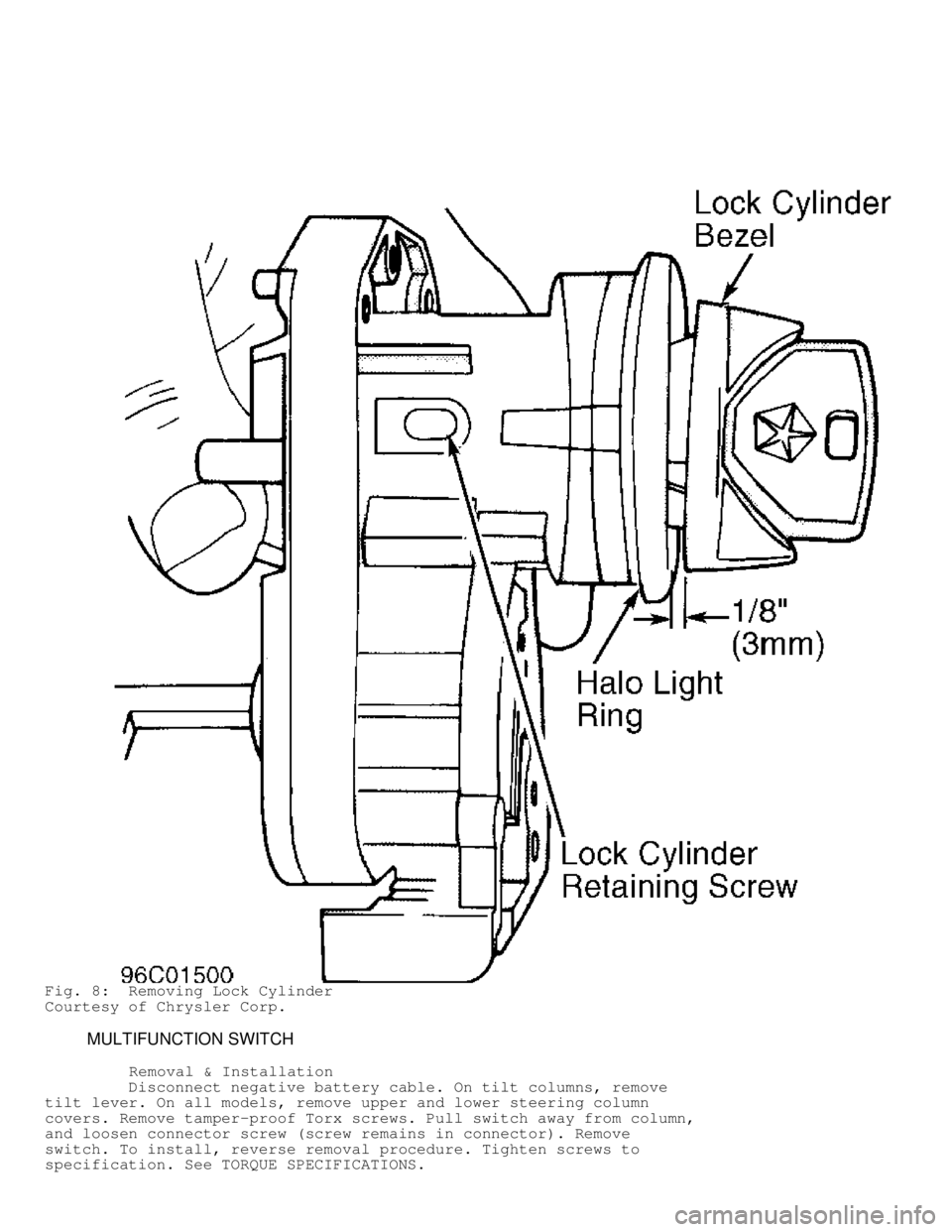
Fig. 8: Removing Lock Cylinder
Courtesy of Chrysler Corp.
MULTIFUNCTION SWITCH
Removal & Installation
Disconnect negative battery cable. On tilt columns, remove
tilt lever. On all models, remove upper and lower steering column
covers. Remove tamper-proof Torx screws. Pull switch away from column,
and loosen connector screw (screw remains in connector). Remove
switch. To install, reverse removal procedure. Tighten screws to
specification. See TORQUE SPECIFICATIONS.
Page 1617 of 1691

bolster. Remove CTM from bracket on inboard side of instrument panel
steering column opening. Disconnect harness connectors. To install,
reverse removal procedure.
INTERMITTENT WIPER RELAY
Removal & Installation
Intermittent wiper relay is located in Power Distribution
Center (PDC) in engine compartment. Remove cover and remove relay. To
install, reverse removal procedures
WIPER ARMS
Removal & Installation
Open hood. Lift wiper and slide latch to hold wiper off of
windshield. With a rocking motion, remove wiper arm. To install,
ensure wiper motor is in park position. Slide wiper arm on shaft.
Align wiper arms. See WIPER BLADES under ADJUSTMENTS.
WIPER MOTOR
NOTE: Wiper linkage and motor module is replaced as a unit.
Removal & Installation
1) Disconnect negative battery cable. Remove wiper arms. See
WIPER ARMS. Remove weatherstrip along front edge of cowl. Release
plastic anchor screws. Lift cowl grille from vehicle. Remove washer
hose from "Y" fitting. Set grille aside.
2) Remove wiper linkage mounting bolts. Turn linkage over and
disconnect harness connector from wiper motor. Remove wiper linkage
and motor module. To install, reverse removal procedure. Align wiper
arms. See WIPER BLADES under ADJUSTMENTS.
WIPER/WASHER SWITCH
NOTE: Wiper/washer switch is part of multifunction steering column
switch. If wiper/washer switch fails, entire multifunction
switch must be replaced.
Removal & Installation
1) Disconnect negative battery cable. Remove tilt lever (if
equipped). Remove steering column upper and lower covers to access
switch connector. Remove switch connector. Remove multifunction switch
tamperproof screws.
2) Gently pull switch away from column and loosen connector
screw (screw remains in connector). Remove switch. To install, reverse\
removal procedure. Tighten screws and nuts to specification. See
TORQUE SPECIFICATIONS. Ensure switch is functioning properly.
WASHER RESERVOIR
Removal & Installation
Disconnect negative battery cable. Drain cooling system.
Disconnect upper radiator hose from radiator. Disconnect harness
connectors from washer pump and washer fluid level sensor. Remove
washer supply hose from washer pump and drain washer fluid. While
pulling reservoir away from fan shroud, lift reservoir upward to
disengage mounting tabs from fan shroud. Remove washer reservoir. To
install, reverse removal procedure.
WASHER MOTOR
Removal & Installation