Page 1579 of 1691
of upper control arm. See WHEEL ALIGNMENT SPECIFICATIONS table.
Tighten pivot retaining bolts. See TORQUE SPECIFICATIONS table.
Fig. 9: Camber & Caster Angle Adjustment Tool
Courtesy of Chrysler Corp.
FRONT WHEEL TOE ADJUSTMENT
Page 1580 of 1691

NOTE: Set each front wheel at 1/2 of total toe specification. On
vehicles equipped with power steering, set wheel toe position
with engine running.
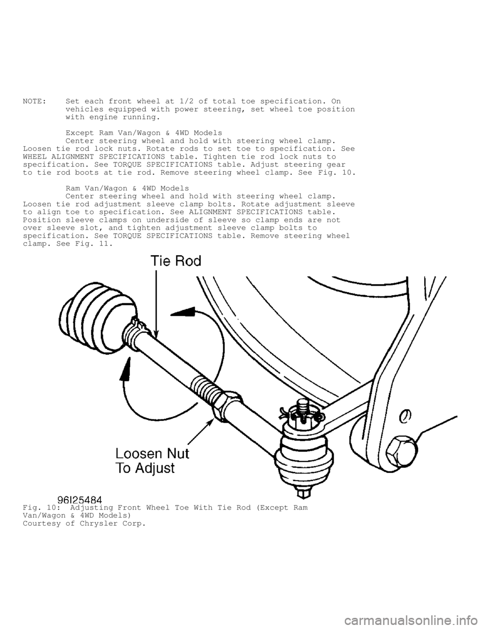
Except Ram Van/Wagon & 4WD Models
Center steering wheel and hold with steering wheel clamp.
Loosen tie rod lock nuts. Rotate rods to set toe to specification. See
WHEEL ALIGNMENT SPECIFICATIONS table. Tighten tie rod lock nuts to
specification. See TORQUE SPECIFICATIONS table. Adjust steering gear
to tie rod boots at tie rod. Remove steering wheel clamp. See Fig. 10.
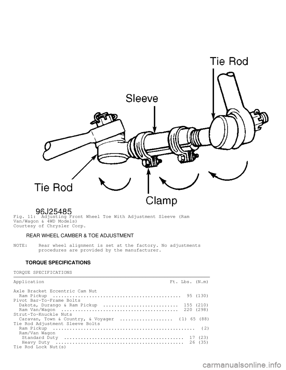
Ram Van/Wagon & 4WD Models
Center steering wheel and hold with steering wheel clamp.
Loosen tie rod adjustment sleeve clamp bolts. Rotate adjustment sleeve
to align toe to specification. See ALIGNMENT SPECIFICATIONS table.
Position sleeve clamps on underside of sleeve so clamp ends are not
over sleeve slot, and tighten adjustment sleeve clamp bolts to
specification. See TORQUE SPECIFICATIONS table. Remove steering wheel
clamp. See Fig. 11.
Fig. 10: Adjusting Front Wheel Toe With Tie Rod (Except Ram
Van/Wagon & 4WD Models)
Courtesy of Chrysler Corp.
Page 1581 of 1691

Fig. 11: Adjusting Front Wheel Toe With Adjustment Sleeve (Ram
Van/Wagon & 4WD Models)
Courtesy of Chrysler Corp.
REAR WHEEL CAMBER & TOE ADJUSTMENT
NOTE: Rear wheel alignment is set at the factory. No adjustments
procedures are provided by the manufacturer.
TORQUE SPECIFICATIONS
TORQUE SPECIFICATIONS������������������\
������������������\
������������������\
������������������\
������������������\
������������������\
������������������\
�������������
Application Ft. Lbs. (N.m)\
Axle Bracket Eccentric Cam Nut
Ram Pickup .............................................. 95 (130)\
Pivot Bar-To-Frame Bolts
Dakota, Durango & Ram Pickup ........................... 155 (210)\
Ram Van/Wagon .......................................... 220 (298)\
Strut-To-Knuckle Nuts
Caravan, Town & Country, & Voyager ................... ( 1) 65 (88)
Tie Rod Adjustment Sleeve Bolts
Ram Pickup ................................................... ( 2)
Ram/Van Wagon
Standard Duty ........................................... 17 (23)\
Heavy Duty .............................................. 26 (35)\
Tie Rod Lock Nut(s)
Page 1588 of 1691

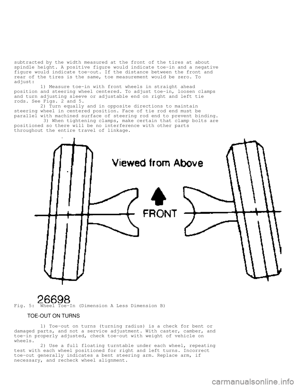
subtracted by the width measured at the front of the tires at about
spindle height. A positive figure would indicate toe-in and a negative
figure would indicate toe-out. If the distance between the front and
rear of the tires is the same, toe measurement would be zero. To
adjust:
1) Measure toe-in with front wheels in straight ahead
position and steering wheel centered. To adjust toe-in, loosen clamps
and turn adjusting sleeve or adjustable end on right and left tie
rods. See Figs. 2 and 5.
2) Turn equally and in opposite directions to maintain
steering wheel in centered position. Face of tie rod end must be
parallel with machined surface of steering rod end to prevent binding.
3) When tightening clamps, make certain that clamp bolts are
positioned so there will be no interference with other parts
throughout the entire travel of linkage.
Fig. 5: Wheel Toe-In (Dimension A Less Dimension B)
TOE-OUT ON TURNS
1) Toe-out on turns (turning radius) is a check for bent or
damaged parts, and not a service adjustment. With caster, camber, and
toe-in properly adjusted, check toe-out with weight of vehicle on
wheels.
2) Use a full floating turntable under each wheel, repeating
test with each wheel positioned for right and left turns. Incorrect
toe-out generally indicates a bent steering arm. Replace arm, if
necessary, and recheck wheel alignment.