Page 1613 of 1691
 ............................... 8 & 9; 2 & 4;")
Switch Position Between Terminals
Off .......................................................... 6 & 7
Delay (1) ............................... 8 & 9; 2 & 4; 1 & 2; 1 & 4
Low .......................................................... 4 & 6
High ......................................................... 4 & 5
Wash ......................................................... 3 & 4
( 1) - At maximum delay position, resistance should be 270-330 k/ohms
between all terminal pairs listed. At minimum delay position,
resistance should be zero when ohmmeter is set on high ohm scale
between all terminal pairs listed.
������������������\
������������������\
������������������\
������������������\
������������������\
������������������\
������������������\
�������������
Fig. 2: Identifying Wiper/Washer Switch Terminals
Courtesy of Chrysler Corp.
SYSTEM TESTS
WARNING: All vehicles are equipped with air bag restraint systems. See
appropriate AIR BAG RESTRAINT SYSTEMS article before
servicing steering wheel or column. Use extreme caution to
avoid personal injury and vehicle damage.
NOTE: If problem occurs in electronic components, wiring, wiper
switch or wiper motor, a Diagnostic Trouble Code (DTC) will
be stored in BCM. For testing procedures, see appropriate
BODY CONTROL COMPUTER TESTS article.
WASHER
NOTE: Following testing applies when pump does not operate. If pump
operates, see TROUBLE SHOOTING.
1) Turn ignition on. Turn wiper switch on. If wipers operate,
go to next step. If wipers do not operate, diagnose wiper problem
first. See WIPER.
Page 1618 of 1691
Disconnect negative battery cable. Remove hose from washer
pump. Drain fluid from reservoir. Disconnect harness connectors from
washer pump. Pry pump away from reservoir, being careful not to
puncture reservoir. Remove and discard grommet. To install, reverse
removal procedure. Use a NEW rubber grommet.
TORQUE SPECIFICATIONS
TORQUE SPECIFICATIONS������������������\
������������������\
������������������\
������������������\
������������������\
������������������\
������������������\
�������������
Application INCH Lbs. (N.m)\
Central Timer Module Screws ............................... 15 (1.6)\
Multifunction Switch Mounting Screws ........................ 17 (2)\
Wiper Motor Mounting Screws ................................. 72 (8)\
Wiper/Washer Switch Screws .................................. 17 (2)\
������������������\
������������������\
������������������\
������������������\
������������������\
������������������\
������������������\
�������������
WIRING DIAGRAMS
Page 1619 of 1691
Fig. 5: Wiper/Washer System Wiring Diagram (Ram Pickup)
Page 1620 of 1691
�L - W IR IN G D IA G RAM S
�
1999 D odge P ic ku p R 1500
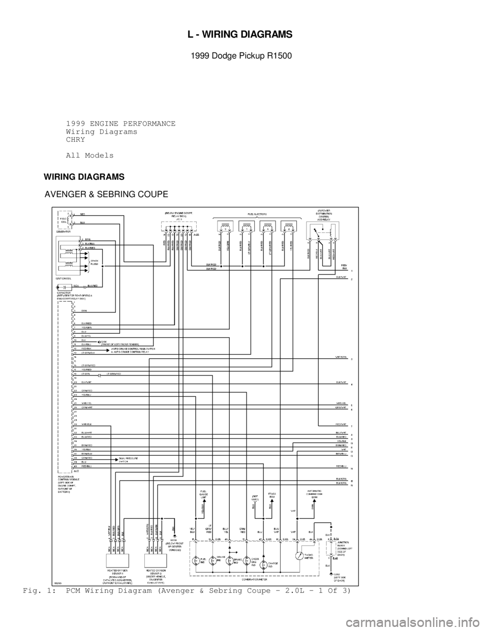
1999 ENGINE PERFORMANCE
Wiring Diagrams
CHRY
All Models
WIRING DIAGRAMS
AVENGER & SEBRING COUPE
Fig. 1: PCM Wiring Diagram (Avenger & Sebring Coupe - 2.0L - 1 Of 3)
Page 1621 of 1691
Fig. 2: PCM Wiring Diagram (Avenger & Sebring Coupe - 2.0L - 2 Of 3)
Page 1622 of 1691
Fig. 3: PCM Wiring Diagram (Avenger & Sebring Coupe - 2.0L - 3 Of 3)
Page 1623 of 1691
Fig. 4: PCM Wiring Diagram (Avenger & Sebring Coupe - 2.5L - 1 Of 3)
Page 1624 of 1691
Fig. 5: PCM Wiring Diagram (Avenger & Sebring Coupe - 2.5L - 2 Of 3)

")
")
")
")
")