1999 DODGE RAM fuel cap
[x] Cancel search: fuel capPage 934 of 1691
Apply light coat of engine oil on NEW .060" (1.5 mm) thick Copper
sealing washer. Install NEW Copper sealing washer on spray tip of fuel
injector. Engine oil is used to aid holding sealing washer in place.
Install new "O" ring on fuel injector. Apply small amount of engine
oil to "O" ring.
2) Ensure fuel inlet hole on side of fuel injector is
positioned toward injector connector tube. Install injector into
cylinder head bore using care not to allow injector tip to touch sides
of bore. Press fuel injector into cylinder head with finger pressure
only. Install fuel injector hold down clamp into shouldered bolt while
aligning slot in top of injector into groove in bottom of clamp.
Tighten opposite clamp bolt to specification. See TORQUE
SPECIFICATIONS.
3) Apply small amount of clean engine oil to NEW "O" ring.
Install "O" ring to fuel injector connector tube. Using finger
pressure only, press injector connector tube into cylinder head.
Connect and tighten high pressure fuel lines to specification. See
TORQUE SPECIFICATIONS.
NOTE: Fuel line fitting torque is important. Mating surfaces will
not seal if fuel line fitting is under or over-torqued.
4) To install remaining components, reverse removal
procedure. Tighten bolts to specification. See TORQUE SPECIFICATIONS.
Bleed high-pressure fuel lines. See FUEL LINE BLEEDING under FUEL
SYSTEM.
FUEL INJECTION PUMP
CAUTION: High-pressure fuel lines must be clamped securely and routed
so they do not contact each other or any other components. DO
NOT weld or substitute high-pressure fuel lines. High
-pressure lines are same length and proper high-pressure fuel
line must be installed in specified area for proper engine
operation.
Removal
1) Disconnect negative battery cables. Clean fuel lines at
cylinder head and injection pump. Clean fuel injection pump and fuel
lines at side of pump. Disconnect 9-pin electrical connector at Fuel
Pump Control Module (FPCM). Place a rag around overflow valve to catch\
excess fuel. Remove overflow valve and disconnect fuel return line.
Remove banjo bolts and fuel supply line at side of injection pump and
top of fuel filter housing.
2) Remove all high pressure fuel lines, intake air tube,
accelerator pedal position sensor, air intake housing, engine oil
dipstick tube, wiring clips, electrical connectors at intake heaters,
and engine lifting bracket. Unscrew plastic access cap at front gear
cover. Remove injection pump gear-to-injection pump shaft nut and
washer.
3) Engine may be rotated by removing dust plug from
transmission adapter plate and installing Engine Barring Tool (Snap-On
SP371) in transmission adapter plate. See Fig. 9. Rotate engine until
keyway is at 12 o'clock position.
Page 938 of 1691
gear. When installing pump, ensure dowel on mounting flange must align
with hole in front of pump. Ensure fuel injection pump is flat against
gear housing. Install 4 fuel injection pump-to-gear housing nuts
finger tight. DO NOT tighten nuts at this time.
CAUTION: DO NOT tighten pump to gear cover using mounting nuts. Damage
to pump or gear cover may result. Pump must be positioned
flat to mounting flange before attempting to tighten mounting
nuts.
4) Install fuel injection pump shaft washer and nut to pump
shaft finger tight. Position lower pump bracket and install 3 bolts
finger tight. Tighten fuel injection pump drive gear nut to
preliminary torque of 22 ft. lbs. (30 N.m). Tighten 4 fuel injection
pump nuts and 3 lower pump bracket-to-pump bolts to specification.
Tighten 2 engine bracket-to-engine bolts to specification. See TORQUE
SPECIFICATIONS Final tighten injection pump shaft nut. Use barring
tool to prevent engine from rotating.
5) Install plastic access cap to front gear cover. Using new
gaskets, install fuel return line and overflow valve to side of
injection pump. Tighten overflow valve to specification. See TORQUE
SPECIFICATIONS Using new gaskets, install fuel supply line to side of
injection pump and top of fuel filter housing. Tighten banjo bolts to
specification. TORQUE SPECIFICATIONS.
6) To complete installation, reverse removal procedure. Bleed
air from fuel system. See FUEL LINE BLEEDING.
FUEL TANK ROLLOVER VALVE
Removal
1) Fuel tank rollover valve is pressed into rubber grommet on
top of fuel tank module. See Fig. 7. Manufacturer recommends removing
fuel tank for access to fuel tank rollover valve.
NOTE: It may be necessary to disconnect fuel lines and electrical
connector from fuel tank module so fuel tank may be lowered
for access to fuel tank rollover valve.
2) Raise and support vehicle. Disconnect negative battery
cables. Drain fuel tank. Remove fuel tank filler tube bolts from body.
Support fuel tank with transmission jack. Remove fuel tank straps and
heat shields (if equipped).
NOTE: Manufacturer recommends replacing rubber grommet on fuel tank
module when servicing fuel tank rollover valve.
3) Slightly lower fuel tank for access to fuel tank rollover
valve. Disconnect electrical connector and fuel lines from fuel tank
module if necessary to gain access to fuel tank rollover valve. Use
proper procedure when disconnecting fuel lines. See FUEL LINE
DISCONNECT FITTINGS under FUEL SYSTEM.
4) Disconnect hose from fuel tank rollover valve. Pry one
side of fuel tank rollover valve from rubber grommet. Remove fuel tank
rollover valve. Remove rubber grommet.
Installation
1) To install, reverse removal procedure using NEW rubber
grommet. If fuel lines were disconnected, install fuel lines on fuel
tank module using proper procedure. See FUEL LINE DISCONNECT FITTINGS
under FUEL SYSTEM.
2) Reinstall fuel tank. Tighten fuel tank strap nuts to
specification. See TORQUE SPECIFICATIONS. Reconnect negative battery
cables.
Page 968 of 1691
Installation
1) If engine has not been rotated after removing distributor,
go to next step. If engine was rotated after removing distributor,
rotate crankshaft clockwise (viewed from front of engine) until
cylinder No. 1 is at Top Dead Center (TDC) on compression stroke and
timing mark on vibration damper aligns with TDC timing mark on timing
chain cover. Go to next step.
2) Ensure distributor mounting area on cylinder block is
clean. Install NEW "O" ring on distributor if necessary. Apply light
coat of engine oil on "O" ring.
3) Position distributor rotor so it aligns with terminal for
cylinder No. 1 on distributor cap. Install distributor. Ensure
distributor engages with slot in oil pump drive gear. Install hold-
down clamp and distributor hold-down bolt. DO NOT tighten distributor
hold-down bolt at this time.
4) Rotate distributor until distributor rotor aligns with
cylinder No. 1 alignment mark on camshaft position sensor. See Fig. 23
. Tighten distributor hold-down bolt to specification. See TORQUE
SPECIFICATIONS. To install remaining components, reverse removal
procedure.
5) Base ignition timing is nonadjustable. Base ignition
timing and timing advance are controlled by the Powertrain Control
Module (PCM). Distributor position is used to determine the fuel
system synchronization. To check for correct distributor position and
fuel system synchronization, see FUEL SYSTEM SYNCHRONIZATION under
FUEL SYSTEM in ON-VEHICLE ADJUSTMENTS article.
IGNITION COIL
Removal & Installation (Dakota 2.5L)
Ignition coil is located on side of engine, near distributor.
Service procedure is primarily an unbolt and bolt-on procedure.
Tighten ignition coil retaining bolts or nuts to specification. See
TORQUE SPECIFICATIONS.
Removal & Installation (Dakota 3.9L, 5.2L & 5.9L, Durango &
Ram Van/Wagon)
1) Ignition coil is located on front of passenger's side
cylinder head. Disconnect spark plug wires and electrical connector
from ignition coil.
CAUTION: Ignition coil-to-cylinder head mounting bracket bolts hold
the idler pulley for the accessory drive belt, as these bolts
are under tension. If necessary to remove these bolts,
accessory drive belt must be removed first.
2) Remove ignition coil retaining bolts or nuts with ignition
coil from the ignition coil mounting bracket. DO NOT remove ignition
coil-to-cylinder head mounting bracket bolts, as these bolts are under
tension.
3) To install, reverse removal procedure. Tighten ignition
coil retaining bolts or nuts to specification. See TORQUE
SPECIFICATIONS.
Removal & Installation (Ram Pickup 3.9L, 5.2L & 5.9L)
1) On 3.9L, 5.2L and 5.9L with light-duty emissions, ignition
coil is located on front of passenger's side cylinder head. On 5.9L
with heavy-duty emissions, ignition coil is located on top of air
injection pump. On all models, disconnect spark plug wires and
electrical connector from ignition coil.
CAUTION: On 3.9L, 5.2L and 5.9L with light-duty emissions, ignition
coil-to-cylinder head mounting bracket bolts hold the idler
Page 969 of 1691
pulley for the accessory drive belt, as these bolts are under
tension. If necessary to remove these bolts, accessory drive
belt must be removed first.
2) Remove ignition coil retaining bolts or nuts with ignition
coil from the ignition coil mounting bracket. On 3.9L, 5.2L and 5.9L
with light-duty emissions, DO NOT remove ignition coil-to-cylinder
head mounting bracket bolts, as these bolts are under tension. On all
applications, to install, reverse removal procedure. Tighten ignition
coil retaining bolts or nuts to specification. See TORQUE
SPECIFICATIONS.
Removal & Installation (Ram Pickup 8.0L)
1) Two separate ignition coils are located above passenger's
side valve cover. Each ignition coil can be serviced separately. On
all ignition coil applications, disconnect spark plug wires and
electrical connector from ignition coil.
2) Remove ignition coil retaining bolts and ignition coil
from ignition coil mounting bracket. To install, reverse removal
procedure. Ensure ignition coil is mounted on ignition coil mounting
bracket with electrical connector facing downward. Tighten ignition
coil retaining bolts to specification. See TORQUE SPECIFICATIONS.
FUEL SYSTEM
FUEL SYSTEM PRESSURE RELEASE
WARNING: Always release fuel pressure before disconnecting any fuel
injection-related component. DO NOT allow fuel to contact
engine or electrical components.
1) Remove fuel cap from fuel tank. Note location of spring
loaded flapper valve inside fuel tank filler tube assembly. Flapper
valve is located just below the fuel cap area on fuel tank filler tube
assembly. Flapper valve is used as a secondary way of sealing the fuel
tank if fuel cap was not properly tightened.
WARNING: When opening flapper valve inside fuel tank filler tube
assembly, ensure a non-metallic object is used to prevent any
sparks.
2) Using a non-metallic object, push flapper valve inside
filler tube assembly downward to release any pressure from the fuel
tank. Ensure all pressure is released from fuel tank.
3) Remove fuel pump relay from Power Distribution Center
(PDC). Fuel pump relay may be identified by label on inside of PDC
cover. See POWER DISTRIBUTION CENTER (PDC) LOCATION table.
4) On all models, start engine and allow engine to idle until
engine stalls. Attempt to restart engine until engine will no longer
run. Turn ignition off.
CAUTION: Ensure steps 1) through 4) are performed before proceeding.
Steps 3) and 4) must be performed to ensure most of the fuel
pressure is released from fuel rails to prevent an excessive
amount of fuel being delivered into the cylinders.
5) Remaining fuel pressure is released by energizing a fuel
injector. Disconnect electrical connector at any fuel injector.
6) Connect jumper wire between one electrical terminal on
fuel injector and positive battery terminal. Connect another jumper
wire on remaining electrical terminal on fuel injector.
Page 983 of 1691
line on fuel rail using proper procedure. Go to step 5).
4) Release fuel pressure from fuel system. See FUEL SYSTEM
PRESSURE RELEASE. Ensure negative battery cable is disconnected.
Remove fuel tank cap to release any residual fuel tank pressure.
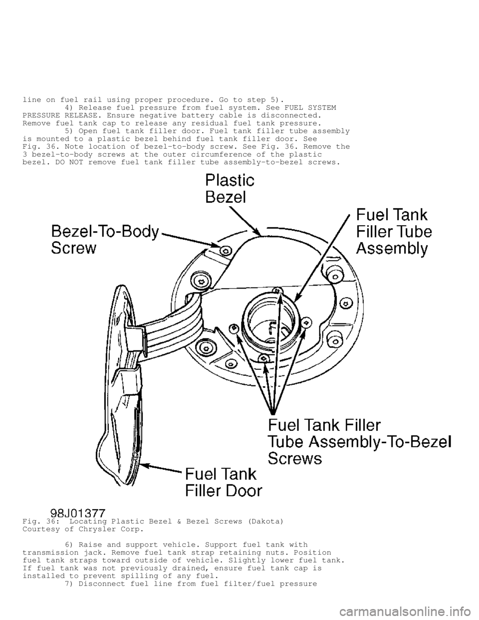
5) Open fuel tank filler door. Fuel tank filler tube assembly
is mounted to a plastic bezel behind fuel tank filler door. See
Fig. 36. Note location of bezel-to-body screw. See Fig. 36. Remove the
3 bezel-to-body screws at the outer circumference of the plastic
bezel. DO NOT remove fuel tank filler tube assembly-to-bezel screws.
Fig. 36: Locating Plastic Bezel & Bezel Screws (Dakota)
Courtesy of Chrysler Corp.
6) Raise and support vehicle. Support fuel tank with
transmission jack. Remove fuel tank strap retaining nuts. Position
fuel tank straps toward outside of vehicle. Slightly lower fuel tank.
If fuel tank was not previously drained, ensure fuel tank cap is
installed to prevent spilling of any fuel.
7) Disconnect fuel line from fuel filter/fuel pressure
Page 985 of 1691
1) To install, reverse removal procedure. If installing small
vent tube and large fill tube on fuel tank, ensure fuel tank fittings
are clean.
2) Install disconnect fitting on fuel tank fitting until
disconnect fitting snaps onto fuel tank fitting. Pull on small vent
tube or and large fill tube to ensure disconnect fitting is locked on
fuel tank fitting. To verify proper installation of disconnect
fitting, ensure the distance between release sleeve and top of fuel
tank fitting is .50" (12.7 mm) on small vent tube or .25" (6.4 mm) o\
n
large fill tube. See Fig. 37.
3) Install fuel lines on fuel filter/fuel pressure regulator
on fuel pump module using proper procedure. See FUEL LINE DISCONNECT
FITTINGS under FUEL SYSTEM.
CAUTION: DO NOT overtighten fuel tank strap retaining nuts during
installation.
4) Tighten fuel tank strap retaining nuts to specification.
See TORQUE SPECIFICATIONS. To install remaining components, reverse
removal procedure. Start engine and check for fuel leaks.
Removal (Durango)
1) Fuel tank may be drained by removing vent hose from rear
of fuel tank, or by pumping fuel from fuel tank using the fuel pump if
fuel pump is operating. If removing vent hose from fuel tank to drain
the fuel, go to step 4). If using fuel pump to drain the fuel tank, go
to next step.
2) Disconnect fuel line from fuel rail. See FUEL LINE AT FUEL
RAIL under FUEL SYSTEM. Connect Fuel Hose (6541, 6539, 6631 or 6923)
for proper engine application at fuel line fitting on fuel rail. Place
remaining end of fuel hose in an approved gasoline container.
3) Connect scan tool to Data Link Connector (DLC). DLC is a
16-pin connector attached to bottom of driver's side of the instrument
panel, just to the right of the brake pedal. Using scan tool
manufacturer's instructions, activate the fuel pump and pump fuel from
fuel tank. Once fuel tank is empty, remove scan tool. Reinstall fuel
line on fuel rail using proper procedure. Go to step 5).
4) Release fuel pressure from fuel system. See FUEL SYSTEM
PRESSURE RELEASE. Ensure negative battery cable is disconnected.
Remove fuel tank cap to release any residual fuel tank pressure.
5) Raise and support vehicle. Remove necessary skid plates
for access to fuel tank. Disconnect vent and filler hose from rear of
fuel tank. If fuel tank was not previously drained, place drain hose
in vent hose fitting at rear of fuel tank. Drain fuel from fuel tank
into an approved gasoline container.
6) Support fuel tank with transmission jack. Remove fuel tank
strap retaining nuts. Position fuel tank straps toward outside of
vehicle. Slightly lower fuel tank. Ensure rear of fuel tank is higher
than front of fuel tank to prevent any spilling any remaining fuel in
fuel tank.
7) Disconnect fuel line from fuel filter/fuel pressure
regulator on fuel pump module using proper procedure for fuel line
disconnect fitting. See FUEL LINE DISCONNECT FITTINGS. Fuel pump
module is located on top of fuel tank. See Fig. 28. Disconnect
electrical connector at fuel pump module. Disconnect vapor line from
rollover valves on top of fuel tank and EVAP line from fuel pump
module. Lower fuel tank from vehicle.
CAUTION: DO NOT overtighten fuel tank strap retaining nuts during
installation.
Installation
1) To install, reverse removal procedure. Install fuel lines
Page 986 of 1691
on fuel filter/fuel pressure regulator on fuel pump module using
proper procedure. See FUEL LINE DISCONNECT FITTINGS.
2) Tighten fuel tank strap retaining nuts to specification.
See TORQUE SPECIFICATIONS. Start engine and check for fuel leaks.
Removal (Ram Pickup)
1) Fuel tank may be drained by lowering fuel tank, or by
pumping fuel from fuel tank using the fuel pump if fuel pump is
operating. If lowering fuel tank to drain the fuel, go to step 4). If
using fuel pump to drain the fuel tank, go to next step.
2) Disconnect fuel line from fuel rail. See FUEL LINE AT FUEL
RAIL. Connect Fuel Hose (6541, 6539, 6631 or 6923) for proper engine
application at fuel line fitting on fuel rail. Place remaining end of
fuel hose in an approved gasoline container.
3) Connect scan tool to Data Link Connector (DLC). DLC is a
16-pin connector attached to bottom of driver's side of the instrument
panel, just straight above the accelerator pedal. Using scan tool
manufacturer's instructions, activate the fuel pump and pump fuel from
fuel tank. Once fuel tank is empty, remove scan tool. Reinstall fuel
line on fuel rail using proper procedure. Go to step 5).
4) Release fuel pressure from fuel system. See FUEL SYSTEM
PRESSURE RELEASE. Ensure negative battery cable is disconnected.
Remove fuel tank cap to release any residual fuel tank pressure.
5) Raise and support vehicle. Open fuel tank filler door.
Remove fuel tank filler tube assembly-to-body screws. Support fuel
tank with transmission jack. Remove fuel tank strap retaining nuts.
6) Slightly lower fuel tank. If fuel tank was not previously
drained, slightly rotate fuel tank so vent hose and filler hose on
fuel tank are above the fuel level in the fuel tank to prevent fuel
leakage when hoses are disconnected. Vent hose and filler hose attach
to fitting on the fuel tank. See Fig. 29.
7) Disconnect vent hose from vent hose fitting on fuel tank.
If fuel tank was previously drained, go to next step. If fuel tank was
not previously drained, place drain hose in vent hose fitting on fuel
tank. Drain fuel from fuel tank into an approved gasoline container.
Go to next step.
8) Disconnect filler hose from filler hose fitting on fuel
tank. Disconnect electrical connector at fuel pump module. Fuel pump
module is located on top of fuel tank. See Fig. 29.
9) Disconnect fuel line from fuel filter/fuel pressure
regulator on fuel pump module using proper procedure for fuel line
disconnect fitting. See FUEL LINE DISCONNECT FITTINGS under FUEL
SYSTEM.
10) Disconnect necessary vapor hoses from rollover valves on
top of fuel tank or fuel pump module. See Fig. 29. Lower fuel tank
from vehicle.
CAUTION: DO NOT overtighten fuel tank strap retaining nuts during
installation.
Installation
1) To install, reverse removal procedure. Install fuel lines
on fuel filter/fuel pressure regulator on fuel pump module using
proper procedure. See FUEL LINE DISCONNECT FITTINGS.
2) Tighten fuel tank strap retaining nuts to specification.
See TORQUE SPECIFICATIONS. Start engine and check for fuel leaks.
Removal (Ram Van & Ram Wagon)
1) Fuel tank may be drained by siphoning fuel out through
small vent hose on fuel and vent hose fitting assembly on fuel tank,
or by pumping fuel from fuel tank using the fuel pump if fuel pump is
operating. If siphoning fuel out through small vent hose on fuel and
vent hose fitting assembly on fuel tank, go to step 4). If using fuel
Page 987 of 1691
pump to drain the fuel tank, go to next step.
2) Disconnect fuel line from fuel rail. See FUEL LINE AT FUEL
RAIL. Connect Fuel Hose (6541, 6539, 6631 or 6923) for proper engine
application at fuel line fitting on fuel rail. Place remaining end of
fuel hose in an approved gasoline container.
3) Connect scan tool to Data Link Connector (DLC). DLC is a
16-pin connector attached to bottom of driver's side of the instrument
panel, just straight above the accelerator pedal. Using scan tool
manufacturer's instructions, activate the fuel pump and pump fuel from
fuel tank. Once fuel tank is empty, remove scan tool. Reinstall fuel
line on fuel rail using proper procedure. Go to step 5).
4) Release fuel pressure from fuel system. See FUEL SYSTEM
PRESSURE RELEASE. Ensure negative battery cable is disconnected.
Remove fuel tank cap to release any residual fuel tank pressure.
5) Raise and support vehicle. Disconnect the small vent hose
from fill and vent hose fitting assembly at driver's side frame rail.
Fill and vent hose fitting assembly is permanently attached on fuel
tank. See Fig. 30.
6) If fuel tank was previously drained, go to next step. If
fuel tank was not previously drained, siphon fuel from fuel tank into
an approved gasoline container by installing siphon hose in small vent
hose fitting on fill and vent hose fitting assembly. Go to next step.
7) Disconnect large fill hose from fill and vent hose fitting
assembly at driver's side frame rail. Fill and vent hose fitting
assembly is permanently attached on fuel tank. See Fig. 30.
8) Support fuel tank with transmission jack. Remove fuel tank
strap retaining nuts from L-shaped bolts securing fuel tank straps on
frame rail. Remove fuel tank straps.
CAUTION: Fill and vent hose fitting assembly must be released from
plastic shield before lowering fuel tank. Use care when
lowering fuel tank as not to damage fill and vent hose
fitting assembly or the fuel tank.
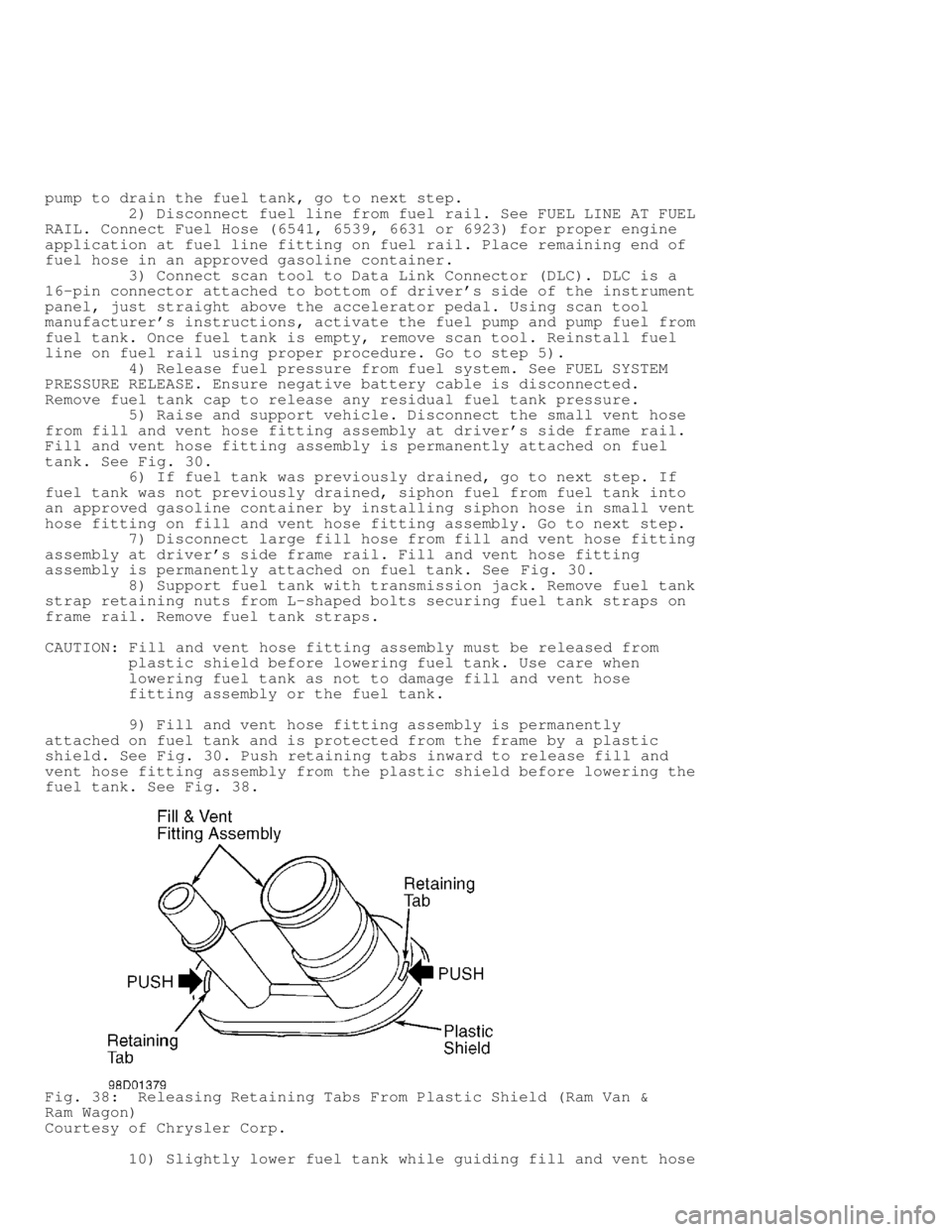
9) Fill and vent hose fitting assembly is permanently
attached on fuel tank and is protected from the frame by a plastic
shield. See Fig. 30. Push retaining tabs inward to release fill and
vent hose fitting assembly from the plastic shield before lowering the
fuel tank. See Fig. 38.
Fig. 38: Releasing Retaining Tabs From Plastic Shield (Ram Van &
Ram Wagon)
Courtesy of Chrysler Corp.
10) Slightly lower fuel tank while guiding fill and vent hose