1999 DODGE RAM front control module
[x] Cancel search: front control modulePage 934 of 1691

Apply light coat of engine oil on NEW .060" (1.5 mm) thick Copper
sealing washer. Install NEW Copper sealing washer on spray tip of fuel
injector. Engine oil is used to aid holding sealing washer in place.
Install new "O" ring on fuel injector. Apply small amount of engine
oil to "O" ring.
2) Ensure fuel inlet hole on side of fuel injector is
positioned toward injector connector tube. Install injector into
cylinder head bore using care not to allow injector tip to touch sides
of bore. Press fuel injector into cylinder head with finger pressure
only. Install fuel injector hold down clamp into shouldered bolt while
aligning slot in top of injector into groove in bottom of clamp.
Tighten opposite clamp bolt to specification. See TORQUE
SPECIFICATIONS.
3) Apply small amount of clean engine oil to NEW "O" ring.
Install "O" ring to fuel injector connector tube. Using finger
pressure only, press injector connector tube into cylinder head.
Connect and tighten high pressure fuel lines to specification. See
TORQUE SPECIFICATIONS.
NOTE: Fuel line fitting torque is important. Mating surfaces will
not seal if fuel line fitting is under or over-torqued.
4) To install remaining components, reverse removal
procedure. Tighten bolts to specification. See TORQUE SPECIFICATIONS.
Bleed high-pressure fuel lines. See FUEL LINE BLEEDING under FUEL
SYSTEM.
FUEL INJECTION PUMP
CAUTION: High-pressure fuel lines must be clamped securely and routed
so they do not contact each other or any other components. DO
NOT weld or substitute high-pressure fuel lines. High
-pressure lines are same length and proper high-pressure fuel
line must be installed in specified area for proper engine
operation.
Removal
1) Disconnect negative battery cables. Clean fuel lines at
cylinder head and injection pump. Clean fuel injection pump and fuel
lines at side of pump. Disconnect 9-pin electrical connector at Fuel
Pump Control Module (FPCM). Place a rag around overflow valve to catch\
excess fuel. Remove overflow valve and disconnect fuel return line.
Remove banjo bolts and fuel supply line at side of injection pump and
top of fuel filter housing.
2) Remove all high pressure fuel lines, intake air tube,
accelerator pedal position sensor, air intake housing, engine oil
dipstick tube, wiring clips, electrical connectors at intake heaters,
and engine lifting bracket. Unscrew plastic access cap at front gear
cover. Remove injection pump gear-to-injection pump shaft nut and
washer.
3) Engine may be rotated by removing dust plug from
transmission adapter plate and installing Engine Barring Tool (Snap-On
SP371) in transmission adapter plate. See Fig. 9. Rotate engine until
keyway is at 12 o'clock position.
Page 967 of 1691
block. Install distributor so distributor shaft engages with slot in
oil pump drive gear. It may be necessary to slightly rotate
distributor during installation.
6) When distributor is fully seated, the distributor rotor
should be at 3 o'clock position and center of hold-down bolt area on
distributor housing should align with distributor hold-down bolt area
on cylinder block.
7) Install hold-down clamp and distributor hold-down bolt.
Tighten distributor hold-down bolt to specification. See TORQUE
SPECIFICATIONS.
8) If installing a factory replacement distributor, remove
plastic alignment pin from distributor housing. If installing original
or used distributor, remove drift from distributor housing and
reinstall camshaft position sensor. On all applications, install
distributor cap and remaining components. Base ignition timing is
nonadjustable, as ignition timing and timing advance are controlled by
the Powertrain Control Module (PCM).
Removal (Dakota 3.9L, 5.2L & 5.9L, Durango, Ram Pickup 3.9L,
5.2L & 5.9L, Ram Van & Ram Wagon)
1) Disconnect negative battery cable. On Ram Van and Ram
Wagon, remove engine cover. On all models, remove air cleaner
assembly. Remove distributor cap. Disconnect electrical connector for
distributor.
2) Rotate crankshaft clockwise (viewed from front of engine)\
until cylinder No. 1 is at Top Dead Center (TDC) on compression stroke\
and timing mark on vibration damper aligns with TDC timing mark on
timing chain cover. Cylinder No. 1 is the front cylinder on driver's
side of engine.
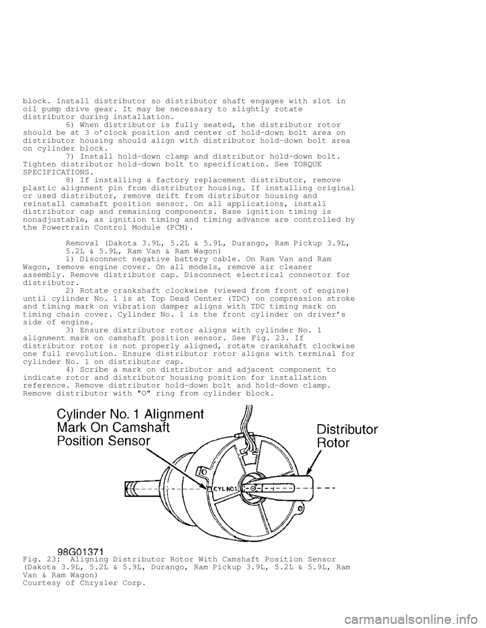
3) Ensure distributor rotor aligns with cylinder No. 1
alignment mark on camshaft position sensor. See Fig. 23. If
distributor rotor is not properly aligned, rotate crankshaft clockwise
one full revolution. Ensure distributor rotor aligns with terminal for
cylinder No. 1 on distributor cap.
4) Scribe a mark on distributor and adjacent component to
indicate rotor and distributor housing position for installation
reference. Remove distributor hold-down bolt and hold-down clamp.
Remove distributor with "O" ring from cylinder block.
Fig. 23: Aligning Distributor Rotor With Camshaft Position Sensor
(Dakota 3.9L, 5.2L & 5.9L, Durango, Ram Pickup 3.9L, 5.2L & 5.9L, Ram
Van & Ram Wagon)
Courtesy of Chrysler Corp.
Page 968 of 1691

Installation
1) If engine has not been rotated after removing distributor,
go to next step. If engine was rotated after removing distributor,
rotate crankshaft clockwise (viewed from front of engine) until
cylinder No. 1 is at Top Dead Center (TDC) on compression stroke and
timing mark on vibration damper aligns with TDC timing mark on timing
chain cover. Go to next step.
2) Ensure distributor mounting area on cylinder block is
clean. Install NEW "O" ring on distributor if necessary. Apply light
coat of engine oil on "O" ring.
3) Position distributor rotor so it aligns with terminal for
cylinder No. 1 on distributor cap. Install distributor. Ensure
distributor engages with slot in oil pump drive gear. Install hold-
down clamp and distributor hold-down bolt. DO NOT tighten distributor
hold-down bolt at this time.
4) Rotate distributor until distributor rotor aligns with
cylinder No. 1 alignment mark on camshaft position sensor. See Fig. 23
. Tighten distributor hold-down bolt to specification. See TORQUE
SPECIFICATIONS. To install remaining components, reverse removal
procedure.
5) Base ignition timing is nonadjustable. Base ignition
timing and timing advance are controlled by the Powertrain Control
Module (PCM). Distributor position is used to determine the fuel
system synchronization. To check for correct distributor position and
fuel system synchronization, see FUEL SYSTEM SYNCHRONIZATION under
FUEL SYSTEM in ON-VEHICLE ADJUSTMENTS article.
IGNITION COIL
Removal & Installation (Dakota 2.5L)
Ignition coil is located on side of engine, near distributor.
Service procedure is primarily an unbolt and bolt-on procedure.
Tighten ignition coil retaining bolts or nuts to specification. See
TORQUE SPECIFICATIONS.
Removal & Installation (Dakota 3.9L, 5.2L & 5.9L, Durango &
Ram Van/Wagon)
1) Ignition coil is located on front of passenger's side
cylinder head. Disconnect spark plug wires and electrical connector
from ignition coil.
CAUTION: Ignition coil-to-cylinder head mounting bracket bolts hold
the idler pulley for the accessory drive belt, as these bolts
are under tension. If necessary to remove these bolts,
accessory drive belt must be removed first.
2) Remove ignition coil retaining bolts or nuts with ignition
coil from the ignition coil mounting bracket. DO NOT remove ignition
coil-to-cylinder head mounting bracket bolts, as these bolts are under
tension.
3) To install, reverse removal procedure. Tighten ignition
coil retaining bolts or nuts to specification. See TORQUE
SPECIFICATIONS.
Removal & Installation (Ram Pickup 3.9L, 5.2L & 5.9L)
1) On 3.9L, 5.2L and 5.9L with light-duty emissions, ignition
coil is located on front of passenger's side cylinder head. On 5.9L
with heavy-duty emissions, ignition coil is located on top of air
injection pump. On all models, disconnect spark plug wires and
electrical connector from ignition coil.
CAUTION: On 3.9L, 5.2L and 5.9L with light-duty emissions, ignition
coil-to-cylinder head mounting bracket bolts hold the idler
Page 992 of 1691
Removal (Dakota & Durango)
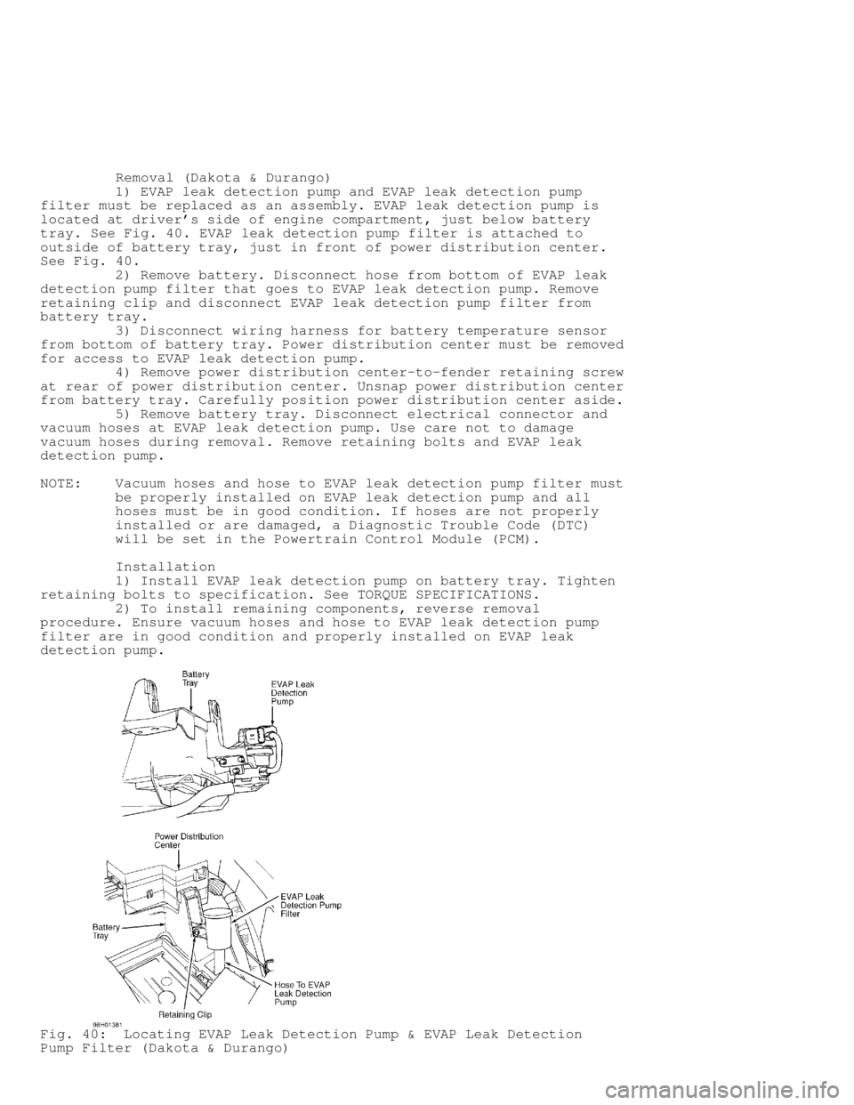
1) EVAP leak detection pump and EVAP leak detection pump
filter must be replaced as an assembly. EVAP leak detection pump is
located at driver's side of engine compartment, just below battery
tray. See Fig. 40. EVAP leak detection pump filter is attached to
outside of battery tray, just in front of power distribution center.
See Fig. 40 .
2) Remove battery. Disconnect hose from bottom of EVAP leak
detection pump filter that goes to EVAP leak detection pump. Remove
retaining clip and disconnect EVAP leak detection pump filter from
battery tray.
3) Disconnect wiring harness for battery temperature sensor
from bottom of battery tray. Power distribution center must be removed
for access to EVAP leak detection pump.
4) Remove power distribution center-to-fender retaining screw
at rear of power distribution center. Unsnap power distribution center
from battery tray. Carefully position power distribution center aside.
5) Remove battery tray. Disconnect electrical connector and
vacuum hoses at EVAP leak detection pump. Use care not to damage
vacuum hoses during removal. Remove retaining bolts and EVAP leak
detection pump.
NOTE: Vacuum hoses and hose to EVAP leak detection pump filter must
be properly installed on EVAP leak detection pump and all
hoses must be in good condition. If hoses are not properly
installed or are damaged, a Diagnostic Trouble Code (DTC)
will be set in the Powertrain Control Module (PCM).
Installation
1) Install EVAP leak detection pump on battery tray. Tighten
retaining bolts to specification. See TORQUE SPECIFICATIONS.
2) To install remaining components, reverse removal
procedure. Ensure vacuum hoses and hose to EVAP leak detection pump
filter are in good condition and properly installed on EVAP leak
detection pump.
Fig. 40: Locating EVAP Leak Detection Pump & EVAP Leak Detection
Pump Filter (Dakota & Durango)
Page 993 of 1691

Courtesy of Chrysler Corp.
Removal (Ram Pickup)
1) EVAP leak detection pump and EVAP leak detection pump
filter must be replaced as an assembly. EVAP leak detection pump and
EVAP leak detection pump filter are located at passenger's side front
corner of engine compartment, near wheelwell. See Fig. 41.
2) Disconnect hose from bottom of EVAP leak detection pump
filter that goes to EVAP leak detection pump. Remove retaining bolt
and EVAP leak detection pump filter.
3) Disconnect electrical connector and vacuum hoses at EVAP
leak detection pump. Use care not to damage vacuum hoses during
removal. Remove retaining bolts and EVAP leak detection pump.
NOTE: Vacuum hoses and hose to EVAP leak detection pump filter must
be properly installed on EVAP leak detection pump and all
hoses must be in good condition. If hoses are not properly
installed or are damaged, a Diagnostic Trouble Code (DTC)
will be set in the Powertrain Control Module (PCM).
Installation
1) Install EVAP leak detection and EVAP leak detection pump
filter. Tighten retaining bolts to specification. See TORQUE
SPECIFICATIONS.
2) To install remaining components, reverse removal
procedure. Ensure vacuum hoses and hose to EVAP leak detection pump
filter are in good condition and properly installed on EVAP leak
detection pump.
Removal (Ram Van & Ram Wagon)
1) EVAP leak detection pump and EVAP leak detection pump
filter must be replaced as an assembly. EVAP leak detection pump and
EVAP leak detection pump filter are located on mounting bracket at
driver's side of engine compartment, near the wheelwell. See Fig. 42.
2) Disconnect electrical connector and vacuum hoses at EVAP
purge solenoid. Use care not to damage vacuum hoses during removal.
Remove EVAP purge solenoid from mounting bracket. Disconnect
electrical connector and vacuum hoses at EVAP leak detection pump. Use
care not to damage vacuum hoses during removal.
3) Remove retaining bolts from mounting bracket. Remove
mounting bracket with EVAP leak detection pump and EVAP leak detection
pump filter as an assembly. Remove retaining bolts, EVAP leak
detection pump and EVAP leak detection pump filter from mounting
bracket.
NOTE: All vacuum hoses and hose to EVAP leak detection pump filter
must be properly installed on EVAP leak detection pump and
all hoses must be in good condition. If hoses are not
properly installed or are damaged, a Diagnostic Trouble Code
(DTC) will be set in the Powertrain Control Module (PCM).
Installation
1) Install EVAP leak detection and EVAP leak detection pump
filter on mounting bracket. Tighten retaining bolts to specification.
See TORQUE SPECIFICATIONS.
2) To install remaining components, reverse removal
procedure. Ensure vacuum hoses and hose to EVAP leak detection pump
filter are in good condition and properly installed.
Page 1228 of 1691

WARNING: Wait about 2 minutes after disconnecting negative battery
cable before servicing air bag system. System reserve
capacitor maintains air bag system voltage for about 2
minutes after battery is disconnected. Servicing air bag
system before 2 minutes may cause accidental air bag
deployment and possible personal injury.
REMOVAL & INSTALLATION
WARNING: All models are equipped with Air Bag Restraint System (ABRS).
See AIR BAG PRECAUTIONS before working on vehicle. Use
caution when working around steering column (air bag could
deploy).
CAUTION: When battery is disconnected, vehicle computer and memory
systems may lose memory data. Driveability problems may exist
until computer systems have completed a relearn cycle. See
COMPUTER RELEARN PROCEDURES article in GENERAL INFORMATION
before disconnecting battery.
HORN PAD & STEERING WHEEL
Removal & Installation
1) Disable air bag system. See AIR BAG DISABLING. Ensure
steering wheel is in straight-ahead position. Remove nuts mounting air
bag module to steering wheel. Remove screws securing cruise control
switch to steering wheel (if equipped).
2) Disconnect wiring connectors. Remove air bag module and
cruise control switch assembly. Pry trim covers from back of steering
wheel and remove horn switch mounting screws. Disconnect horn wires.
Remove horn switch.
3) Remove steering wheel retaining nut. Reference mark
steering wheel and steering shaft. Using puller, remove steering
wheel. To install, reverse removal procedure. Align marks made during
removal. Tighten steering wheel retaining nut to specification.
STEERING COLUMN
Removal & Installation
1) Position front wheels straight ahead. Disconnect and
isolate negative battery cable. On column shift models, remove link
rod from bushing in shift lever. Discard bushing. On all models,
remove steering wheel using Puller (C-3428-B). See HORN PAD & STEERING\
WHEEL.
2) Remove steering column shaft-to-coupler retaining pin.
Push upper coupler shaft down into lower steering coupler. Remove dash
panel column cover. On column shift models, disconnect shift indicator
cable.
3) On all models, remove tilt lever (if equipped). Remove
upper and lower shroud. Remove lower fixed shroud. Disconnect
multifunction switch harness connector. Disconnect harness connectors
from ignition switch, key-in light, horn and cruise control (if
equipped).
4) Loosen upper support bracket nuts and allow column to drop
slightly. Remove upper fixed shroud. Disconnect wiring harness
retainers from column, and move harness to one side. Remove lower dash
panel. Remove lower steering column nuts. Remove column.
CAUTION: DO NOT reuse bushing in shift rod lever once shift rod is
removed. Always install a NEW bushing.
5) To install column, reverse removal procedure. Connect
Page 1383 of 1691

Transmission Overdrive Switch (A/T Models)
See TRANSMISSION under MISCELLANEOUS CONTROLS.
RELAYS & SOLENOIDS
RELAYS
A/C Clutch Relay
A/C clutch relay may also be referred to as A/C compressor
clutch relay. A/C clutch relay is located in power distribution center
at driver's side front corner of engine compartment, near battery. If
problem exists in A/C clutch relay or wiring circuit, a Diagnostic
Trouble Code (DTC) will be stored in Powertrain Control Module (PCM)\
.
See DTC P0645 in SELF-DIAGNOSTICS - JEEP, TRUCKS & RWD VANS article.
Auto Shutdown (ASD) Relay
ASD relay is located in power distribution center at driver's
side front corner of engine compartment, near battery. If problem
exists in ASD relay or wiring circuit, a Diagnostic Trouble Code (DTC)\
will be stored in Powertrain Control Module (PCM). See SELF-
DIAGNOSTICS - JEEP, TRUCKS & RWD VANS article.
Fuel Heater Relay
1) Fuel heater relay is located in Power Distribution Center
(PDC) next to left battery. Refer to PDC lid for relay location.
Remove relay and note terminal identification on relay. See Fig. 3.
2) Using ohmmeter, check resistance between terminals No. 85
and 86 on relay. Resistance should be 70-80 ohms. If resistance is
within specification, go to next step. If resistance is not within
specification, replace relay.
3) Using ohmmeter, ensure continuity exists between terminals
No. 30 and 87A on relay. If continuity exists, go to next step. If no
continuity exists, replace relay.
4) Using ohmmeter, ensure no continuity exists between
terminals No. 30 and 87 on relay. If no continuity exists, go to next
step. If continuity exists, replace relay.
5) Using jumper wires, connect terminal No. 85 to negative
side of 12-volt power source and terminal No. 86 to positive side of
12-volt power source. Using ohmmeter, ensure no continuity now exists
between terminals No. 30 and 87A on relay. If no continuity exists, go
to next step. If continuity exists, replace relay.
CAUTION: DO NOT allow ohmmeter leads to contact terminals No. 85 and
86 on relay when checking resistance.
6) Using ohmmeter, ensure continuity now exists between
terminals No. 30 and 87 on relay. If continuity exists, disconnect
jumper wires from relay. If no continuity exists, replace relay.
NOTE: For additional information on checking wiring circuit for
fuel heater relay, see TEST NTC-1: NO TROUBLE CODE TEST MENU
and TEST NS-SEL: NO START TEST SELECTION in SELF-DIAGNOSTICS
- JEEP, TRUCKS & RWD VANS article.
Page 1385 of 1691
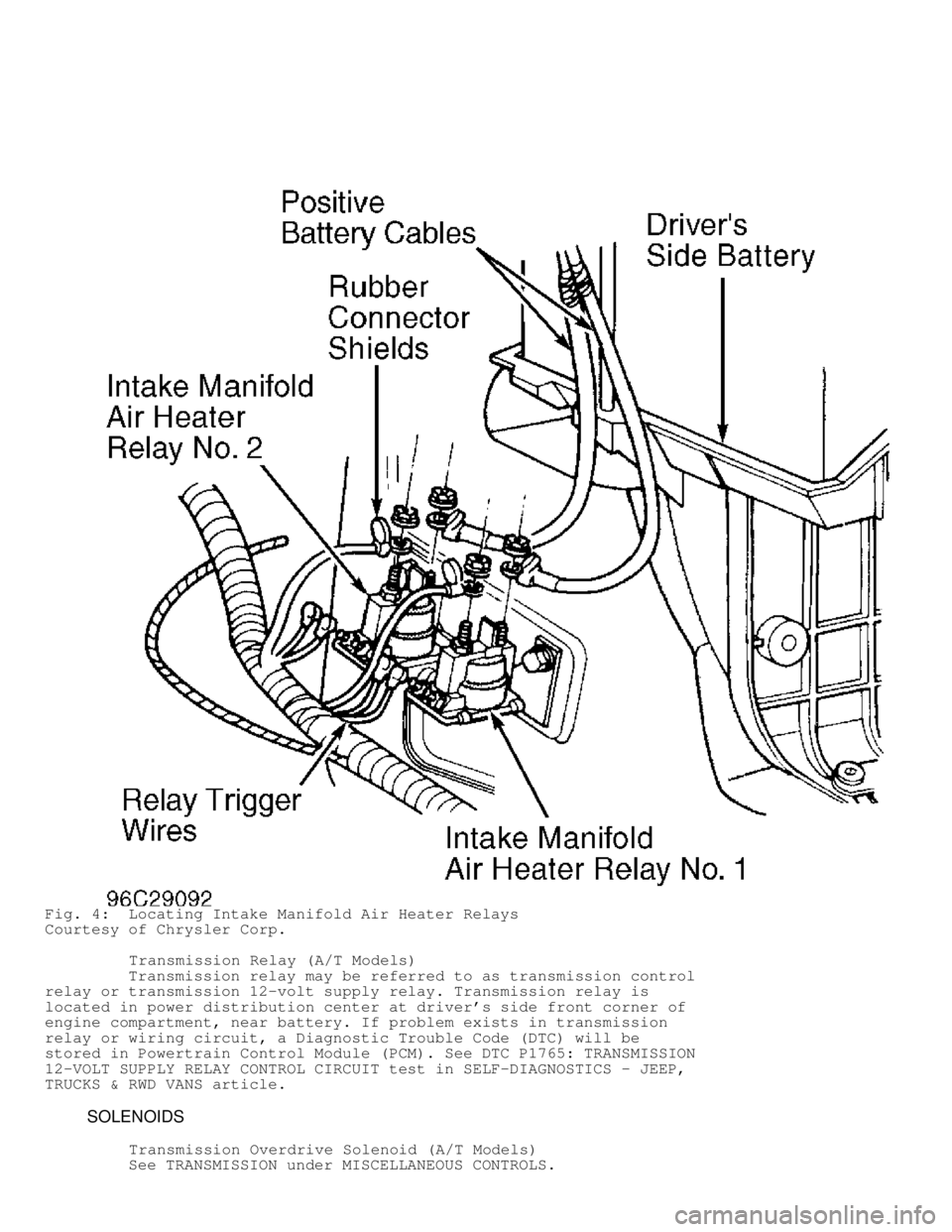
Fig. 4: Locating Intake Manifold Air Heater Relays
Courtesy of Chrysler Corp.
Transmission Relay (A/T Models)
Transmission relay may be referred to as transmission control
relay or transmission 12-volt supply relay. Transmission relay is
located in power distribution center at driver's side front corner of
engine compartment, near battery. If problem exists in transmission
relay or wiring circuit, a Diagnostic Trouble Code (DTC) will be
stored in Powertrain Control Module (PCM). See DTC P1765: TRANSMISSION\
12-VOLT SUPPLY RELAY CONTROL CIRCUIT test in SELF-DIAGNOSTICS - JEEP,
TRUCKS & RWD VANS article.
SOLENOIDS
Transmission Overdrive Solenoid (A/T Models)
See TRANSMISSION under MISCELLANEOUS CONTROLS.