1999 DODGE RAM cruise control
[x] Cancel search: cruise controlPage 926 of 1691

Removal (A/T Models)
Raise and support vehicle. Disconnect electrical connector
from park/neutral switch. Park/neutral switch is located on side of
transmission case, near shift linkage. Unscrew park/neutral switch
from transmission case. Remove seal ring from park/neutral switch.
Installation
1) Apply parking brake. Place shift lever in Park and
Neutral. Ensure park/neutral switch operating levers in transmission
are centered in the park/neutral switch opening on transmission case.
2) Using NEW seal ring, install park/neutral switch. Tighten
park/neutral switch to specification. See TORQUE SPECIFICATIONS.
Install electrical connector. Add ATF as necessary.
ACCELERATOR PEDAL POSITION SENSOR (APPS)
NOTE: APPS is replaced as assembly, including lever, brackets, and
sensor.
Removal
1) Disconnect negative battery cables. Remove cable cover.
Using finger pressure only, disconnect end of speed control servo
cable from throttle lever pin by pulling forward on connector while
holding lever rearward. Using 2 small screwdrivers, pry throttle cable
connector socket from throttle lever ball.
2) Disconnect transmission kickdown cable (if equipped).
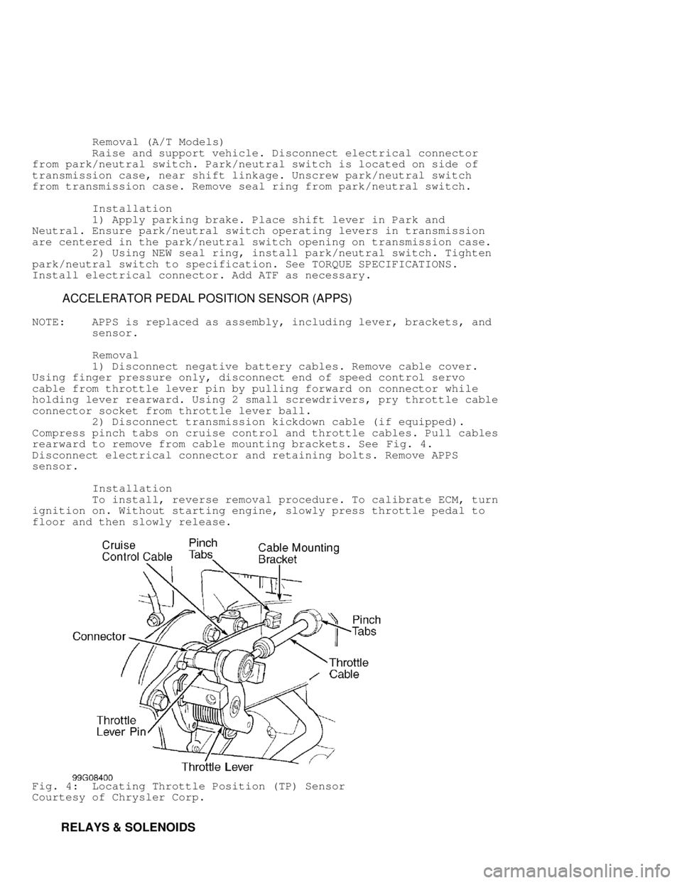
Compress pinch tabs on cruise control and throttle cables. Pull cables
rearward to remove from cable mounting brackets. See Fig. 4.
Disconnect electrical connector and retaining bolts. Remove APPS
sensor.
Installation
To install, reverse removal procedure. To calibrate ECM, turn
ignition on. Without starting engine, slowly press throttle pedal to
floor and then slowly release.
Fig. 4: Locating Throttle Position (TP) Sensor
Courtesy of Chrysler Corp.
RELAYS & SOLENOIDS
Page 1228 of 1691

WARNING: Wait about 2 minutes after disconnecting negative battery
cable before servicing air bag system. System reserve
capacitor maintains air bag system voltage for about 2
minutes after battery is disconnected. Servicing air bag
system before 2 minutes may cause accidental air bag
deployment and possible personal injury.
REMOVAL & INSTALLATION
WARNING: All models are equipped with Air Bag Restraint System (ABRS).
See AIR BAG PRECAUTIONS before working on vehicle. Use
caution when working around steering column (air bag could
deploy).
CAUTION: When battery is disconnected, vehicle computer and memory
systems may lose memory data. Driveability problems may exist
until computer systems have completed a relearn cycle. See
COMPUTER RELEARN PROCEDURES article in GENERAL INFORMATION
before disconnecting battery.
HORN PAD & STEERING WHEEL
Removal & Installation
1) Disable air bag system. See AIR BAG DISABLING. Ensure
steering wheel is in straight-ahead position. Remove nuts mounting air
bag module to steering wheel. Remove screws securing cruise control
switch to steering wheel (if equipped).
2) Disconnect wiring connectors. Remove air bag module and
cruise control switch assembly. Pry trim covers from back of steering
wheel and remove horn switch mounting screws. Disconnect horn wires.
Remove horn switch.
3) Remove steering wheel retaining nut. Reference mark
steering wheel and steering shaft. Using puller, remove steering
wheel. To install, reverse removal procedure. Align marks made during
removal. Tighten steering wheel retaining nut to specification.
STEERING COLUMN
Removal & Installation
1) Position front wheels straight ahead. Disconnect and
isolate negative battery cable. On column shift models, remove link
rod from bushing in shift lever. Discard bushing. On all models,
remove steering wheel using Puller (C-3428-B). See HORN PAD & STEERING\
WHEEL.
2) Remove steering column shaft-to-coupler retaining pin.
Push upper coupler shaft down into lower steering coupler. Remove dash
panel column cover. On column shift models, disconnect shift indicator
cable.
3) On all models, remove tilt lever (if equipped). Remove
upper and lower shroud. Remove lower fixed shroud. Disconnect
multifunction switch harness connector. Disconnect harness connectors
from ignition switch, key-in light, horn and cruise control (if
equipped).
4) Loosen upper support bracket nuts and allow column to drop
slightly. Remove upper fixed shroud. Disconnect wiring harness
retainers from column, and move harness to one side. Remove lower dash
panel. Remove lower steering column nuts. Remove column.
CAUTION: DO NOT reuse bushing in shift rod lever once shift rod is
removed. Always install a NEW bushing.
5) To install column, reverse removal procedure. Connect
Page 1231 of 1691

Hazard Warning Lights Okay To Front Lights Only
Faulty external bulbs. Faulty contact in turn signal/hazard
switch. Open circuit between hazard switch and turn signal switch.
Open or grounded circuit in wiring to rear lights.
Hazard Warning Lights Okay To Rear Lights Only
Faulty external bulbs. Faulty contact in turn signal/hazard
switch. Open or grounded circuit in wiring to front lights.
Indicator Light Inoperative, External Lights Okay
Burned-out indicator bulb in instrument cluster. Faulty
contact. Open circuit.
Indicator Light Okay, External Lights Inoperative
Open circuit in wiring to external light(s).
Indicator Light Okay, External Lights Glow Dimly Or Do Not
Flash
Loose or corroded external light connections. Poor ground
circuit at external light(s).
Turn Signals Do Not Cancel After Turn
Broken canceling pawl on turn signal switch. Improperly
aligned canceling cam. Broken or loose canceling cam.
Turn Signals Inoperative (Both Sides)
Blown fuse. Faulty turn signal flasher. Loose bulkhead
connector. Loose or faulty rear wiring harness or terminals. Open
circuit to turn signal flasher. Open circuit in feed wire to turn
signal switch. Faulty switch connections. Open or grounded circuit in
wiring to external lights.
Turn Signal Inoperative (One Side)
Faulty external bulb. Poor ground at external light. Open
circuit in wiring to external light(s). Faulty turn signal/hazard
switch.
COMPONENT TESTS
CAUTION: When battery is disconnected, vehicle computer and memory
systems may lose memory data. Driveability problems may exist
until computer systems have completed a relearn cycle. See
COMPUTER RELEARN PROCEDURES article in GENERAL INFORMATION
before disconnecting battery.
NOTE: For additional testing procedures, see appropriate CRUISE
CONTROL SYSTEMS and WIPER/WASHER SYSTEMS articles.
NOTE: For component locations, see COMPONENT LOCATIONS.
HORN RELAY
1) Remove horn relay from Power Distribution Center (PDC).
Use label on PDC cover to identify and locate relay. Check continuity
between relay terminals No. 87A and 30. See Fig. 1. If continuity does
not exist, replace relay. If continuity exists, go to next step.
2) Check continuity between relay terminals No. 30 and 87. If
continuity exists, replace relay. If continuity does not exist, check
resistance between relay terminals No. 85 and 86. If resistance is not
70-80 ohms, replace relay. If resistance is 70-80 ohms, go to next
step.
3) Using jumper wires, connect positive battery voltage to
Page 1403 of 1691

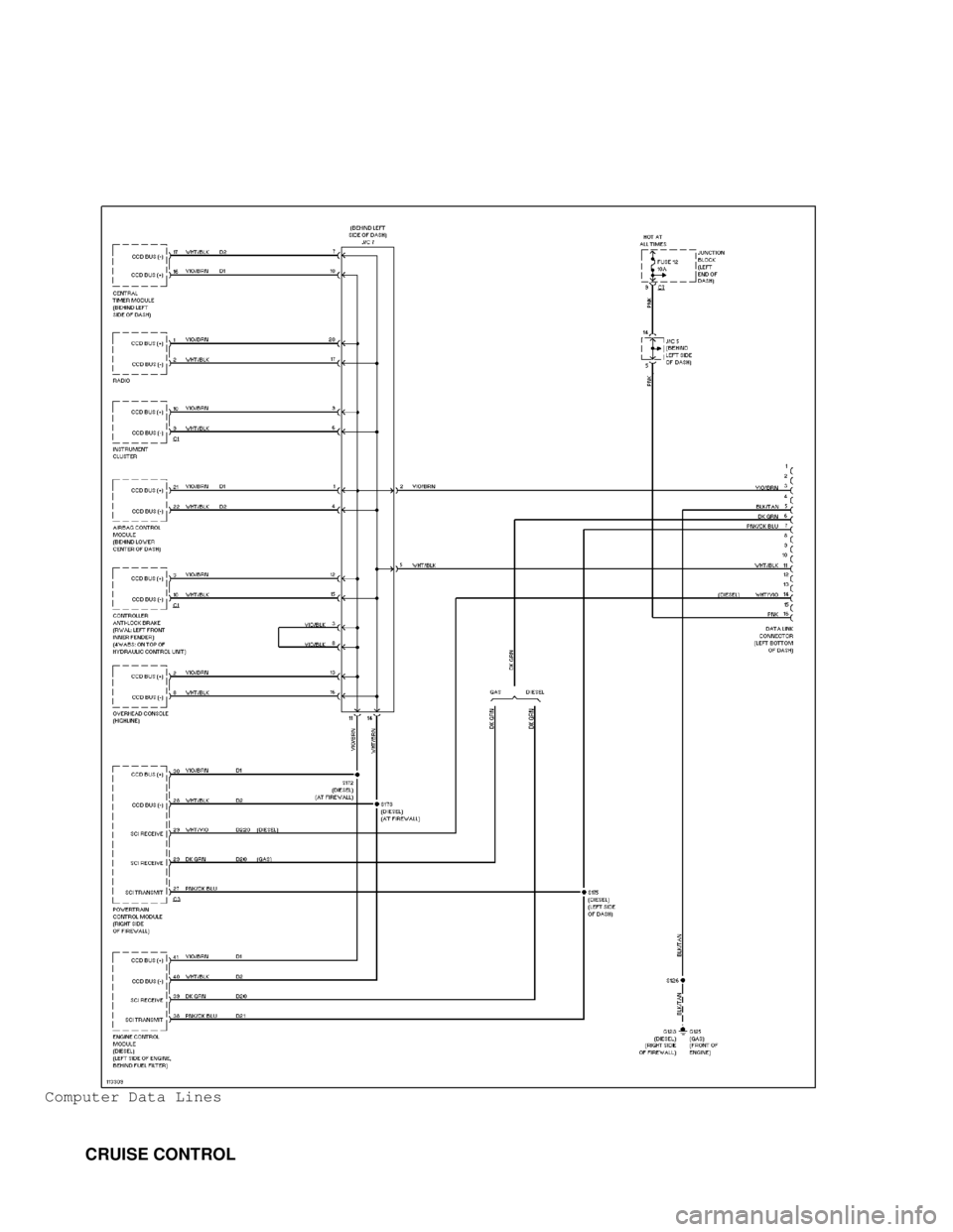
Computer Data Lines
CRUISE CONTROL
Page 1404 of 1691

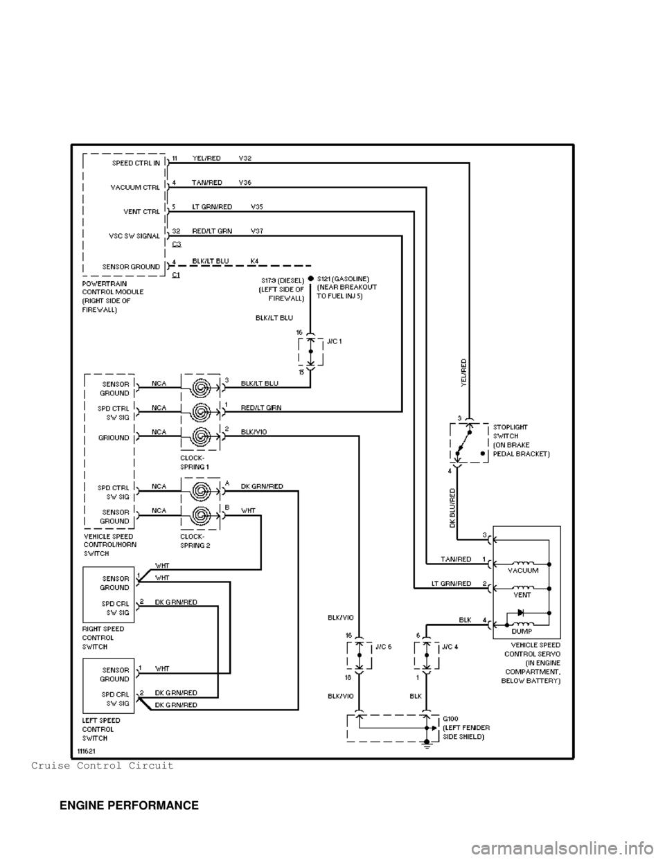
Cruise Control Circuit
ENGINE PERFORMANCE
Page 1462 of 1691

* Charging System
* Cruise Control System
* Intake Manifold Air Heater
* Tachometer
* Torque Convertor Clutch Engagement (A/T Only)
* Transmission Overdrive Solenoid (A/T Only) Components are
grouped into 2 categories. The first category covers INPUT
DEVICES, which control or produce voltage signals monitored
by the PCM. The second category covers OUTPUT SIGNALS, which
are components controlled by the PCM. See PCM INPUT SIGNALS
and ECM/PCM OUTPUT SIGNALS.
ECM INPUT SIGNALS
Accelerator Pedal Position Sensor (APPS)
APPS sensor is mounted on top left of engine. See Fig. 2.
Sensor provides DC voltage input signal to Engine Control Module (ECM)\
to indicate throttle position. On previous engines, there were
linkages between accelerator pedal, throttle position sensor and
injection pump. On this engine, no linkage exists between accelerator
pedal and injection pump. ECM uses input signals from APPS sensor to
determine proper fuel delivery. ECM also outputs this signal to PCM.
Battery Voltage
Battery voltage input signal provides operating voltage to
Engine Control Module (ECM). This input signal keeps ECM memory alive
and informs ECM what generator output voltage is when engine is
running. ECM memory is used to store Diagnostic Trouble Codes (DTCs),
store APPS sensor voltages from previous key cycles and provide a
speed control adaptive memory.
Camshaft Position Sensor (CMP)
Camshaft Position (CMP) sensor is a hall effect sensor (0-5
volts switched), located below injection pump in rear face of timing
gear cover. Sensor is not used for fuel control. Sensor is used only
for diagnostic purposes.
CCD Bus Circuits
These circuits are connected between Engine Control Module
(ECM) and Powertrain Control Module (PCM) to allow communication
between modules.
Crankshaft Position Sensor (CKP)
Crankshaft Position (CKP) sensor delivers input signal (35
tooth wheel with gap) to Engine Control Module (ECM) to indicate
engine speed and crankshaft position. ECM uses CKP signal along with
other input signals for controlling injector firing sequence and
timing. Sensor is located below fuel transfer pump, on side of engine
block. See Fig. 2.
Data Link Connector (DLC)
Data Link Connector (DLC) provides an input signal to Engine
Control Module (ECM) when using scan tool to retrieve Diagnostic
Trouble Codes (DTCs) from ECM. Input signal may also be used when
performing various tests on the ECM and electronic control system.
Data link connector is a 16-pin connector located at lower edge of
driver's side of instrument panel, just above accelerator pedal.
Engine Coolant Temperature (ECT) Sensor
Engine coolant temperature sensor delivers input signal to
Engine Control Module (ECM) to indicate engine coolant temperature.
ECM uses input signal for controlling fuel control and timing. Engine
coolant temperature sensor is located on front of head, near
Page 1465 of 1691

located in power distribution center at driver's side front corner of
engine compartment, near the battery. Automatic Shutdown (ASD) relay
may also be referred to as Auto Shutdown (ASD) relay.
Battery Temperature Sensor
Battery temperature sensor delivers input signal to
Powertrain Control Module (PCM) to indicate the battery temperature.
PCM uses battery temperature input to modify rate of output from the
charging system. Battery temperature sensor is snapped into battery
tray below driver's side battery.
Battery Voltage
Battery voltage input signal provides operating voltage to
Powertrain Control Module (PCM). This input signal keeps PCM memory
alive and informs PCM what generator output voltage is when engine is
running. PCM memory is used to store Diagnostic Trouble Codes (DTCs),
store APPS sensor voltages from previous key cycles and provide a
speed control adaptive memory.
Brake Switch
Brake switch delivers input signal to Powertrain Control
Module (PCM) to indicate when brakes are applied. PCM uses input
signal for controlling cruise control system and transmission torque
converter clutch operation on A/T models. Brake switch is located near
top of brake pedal and may also be referred to as brakelight switch.
CKP Sensor
Crankshaft Position (CKP) sensor delivers input signal (35
tooth wheel with gap) to Engine Control Module (ECM) to indicate
engine speed and crankshaft position. ECM uses CKP signal along with
other input signals for controlling injector firing sequence and
timing. Sensor is located below fuel transfer pump, on side of engine
block. See Fig. 2.
Cruise Control System Switches
Cruise control system functions, controlled by momentary
contact switches, are monitored through multiplexed input signal to
Powertrain Control Module (PCM). Resistance monitored at this input
signal, in conjunction with the length of time the PCM measures the
resistance, determines which switch feature has been selected.
Data Link Connector (DLC)
Data Link Connector (DLC) provides an input signal to
Powertrain Control Module (PCM) when using scan tool to retrieve
Diagnostic Trouble Codes (DTCs) from PCM. Input signal may also be
used when performing various tests on the PCM and electronic control
system. DLC is a 16-pin connector located at lower edge of driver's
side of instrument panel, just above accelerator pedal.
Fuel Level Sensor
The Powertrain Control Module (PCM) sends a 5-volt signal to
the fuel level sensor. The fuel level sensor will return a signal to
PCM. This signal is used for fuel gauge operation and to prevent
setting a false misfire or fuel system trouble codes. If fuel level is
less than 15 percent, PCM will not set code.
Ignition Sense
Ignition switch position input to Powertrain Control Module
(PCM). PCM uses input to determine proper output functions, including
cruise control, generator output, sensor supply and transmission
functions.
Transmission Speed Sensor (A/T Models)
Page 1466 of 1691

Transmission speed sensor may also be referred to as
transmission output shaft speed sensor. Transmission speed sensor is
located on overdrive case at rear of transmission. Transmission speed
sensor delivers input signal to Powertrain Control Module (PCM) to
indicate transmission output shaft speed.
Overdrive Switch (A/T Models)
Transmission overdrive switch may be referred to as
overdrive/override switch, OD switch or overdrive off switch.
Transmission overdrive switch is located on end of gearshift lever.
When vehicle operator depresses transmission overdrive switch, an
input signal is delivered to the Powertrain Control Module (PCM). The
PCM uses input signal for controlling transmission overdrive shifts by
use of transmission overdrive solenoid on transmission valve body.
Transmission overdrive switch is normally in the ON position, allowing
transmission overdrive operation. If transmission overdrive switch is
depressed once, switch is in OFF position, allowing no transmission
overdrive upshift. If transmission overdrive switch is depressed
again, switch returns to the ON position, allowing transmission
overdrive operation.
Park/Neutral Switch (A/T Models)
Park/neutral switch delivers input signal to Powertrain
Control Module (PCM) to indicate if transmission is in Park, Neutral
or Drive. PCM uses input signal for controlling cruise control system,
transmission torque converter clutch operation and transmission
overdrive solenoid. When park/neutral switch is in Park or Neutral,
switch also provides a ground circuit for the engine starting system.
Park/neutral switch is located on the driver's side of transmission,
near shift linkage.
Transmission Governor Pressure Sensor (A/T Models)
Transmission governor pressure sensor delivers input signal
to Powertrain Control Module (PCM) to indicate transmission governor
pressure. PCM uses input signal for controlling governor pressure by
use of governor pressure solenoid on transmission valve body.
Transmission Temperature Sensor (A/T Models)
Transmission temperature sensor monitors transmission fluid
temperature and delivers input signal to Powertrain Control Module
(PCM). PCM uses input signal for controlling transmission torque
converter clutch operation, transmission overdrive shifts and governor
pressure. Transmission temperature sensor is located on transmission
valve body, incorporated into governor pressure sensor.
PCM prevents torque converter clutch engagement and
transmission overdrive operation when transmission fluid temperature
is less than 50
�F (10�C). If transmission fluid temperature is more
than 260�F (126�C), PCM forces a 4-3 downshift and engages torque
converter clutch until transmission fluid cools down. Once
transmission fluid cools to less than 230
�F (110�C), PCM allows a 3-4
shift again.
Vehicle Speed & Distance
Vehicle speed sensor is no longer used. The vehicle speed and
distance traveled are determined by rear wheel speed sensor. Rear
wheel speed sensor is mounted on top of rear axle housing, above the
ring gear. Rear wheel speed sensor delivers an input signal to
Controller Anti-Lock Brake (CAB) to indicate vehicle speed and
distance traveled. The CAB then delivers input signal to Powertrain
Control Module (PCM) to indicate vehicle speed and distance traveled.
PCM uses input signal for controlling control cruise control system
and fuel system. The CAB is mounted on top of the hydraulic control
unit. Hydraulic control unit contains the pump assembly that