�
N - R EM OVE/IN STA LL/O VER HAU L - R W D - G ASO LIN E
�
1999 D odge P ic ku p R 1500
1999 ENGINE PERFORMANCE
CHRY - Removal, Overhaul & Installation - Gasoline
Dakota, Durango, Ram Pickup, Ram Van, Ram Wagon
CAUTION: When battery is disconnected, vehicle computer and memory
systems may lose memory data. Driveability problems may exist
until computer systems have completed a relearn cycle. See
COMPUTER RELEARN PROCEDURES article in GENERAL INFORMATION
before disconnecting battery.
INTRODUCTION
Removal, overhaul and installation procedures are covered in
this article. If component removal and installation is basically an
unbolt and bolt-on procedure, only a torque specification may be
provided.
COMPUTERIZED ENGINE CONTROLS
POWERTRAIN CONTROL MODULE (PCM)
NOTE: If replacing Powertrain Control Module (PCM), the correct
vehicle mileage and Vehicle Identification Number (VIN) must
be programmed into the PCM to prevent Diagnostic Trouble
Codes (DTCs) from being set in the Anti-Lock Brake System
(ABS) module and Supplemental Restraint System (SRS) module\
.
To program PCM and clear DTCs from ABS and SRS modules, see
PCM PROGRAMMING. If replacing Powertrain Control Module (PCM)\
on models equipped with a Smart Key Immobilizer Module
(SKIM), the secret key data must also be updated to enable
engine starting. To update secret key data, see PCM
PROGRAMMING.
Removal & Installation
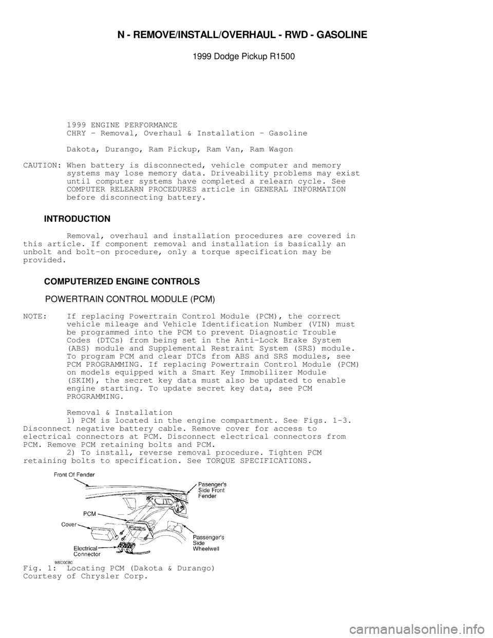
1) PCM is located in the engine compartment. See Figs. 1-3.
Disconnect negative battery cable. Remove cover for access to
electrical connectors at PCM. Disconnect electrical connectors from
PCM. Remove PCM retaining bolts and PCM.
2) To install, reverse removal procedure. Tighten PCM
retaining bolts to specification. See TORQUE SPECIFICATIONS.
Fig. 1: Locating PCM (Dakota & Durango)
Courtesy of Chrysler Corp.
Procedure For Programming PCM & Clearing DTCs From ABS & SRS
Modules
Connect scan tool to Data Link Connector (DLC). DLC is
located under left side of instrument panel. Using scan tool, enter
correct VIN and mileage into PCM. Using scan tool manufacturer's
instructions, clear DTCs from ABS and SRS modules.
Procedure For Updating Secret Key Data
1) Connect scan tool to Data Link Connector (DLC). DLC is
located under left side of instrument panel.
2) Go to ENGINE and then MISC menus on scan tool. Place the
SKIM in SECURED ACCESS MODE by using the appropriate Personal
Identification Number (PIN) for this vehicle. PIN may be obtained from\
the owner, vehicle's invoice, or from the manufacturer. Select UPDATE
THE SECRET KEY DATA. The data will be transferred from Smart Key
Immobilizer Module (SKIM) to the PCM, allowing the vehicle to start.
NOTE: On Ram Van and Ram Wagon, if 3 attempts are made to enter the
SECURED ACCESS MODE using the incorrect Personal
Identification Number (PIN), the SECURED ACCESS MODE will be
locked out for one hour. To exit this locked out mode, leave
ignition switch in the ON position for one hour with all
accessories turned off. It may be necessary to monitor
battery state and connect a battery charger if necessary.
ENGINE SENSORS & SWITCHES
BATTERY TEMPERATURE SENSOR
Removal & Installation
Battery temperature sensor is snapped into center of battery
tray, directly below the battery. Remove battery. Disconnect
electrical connector for battery temperature sensor. Pry battery
temperature sensor straight upward from battery tray. To install,
reverse removal procedure.
BRAKE SWITCH
NOTE: Brake switch may also be referred to as brakelight switch or
stoplight switch.
Removal (Dakota, Durango & Ram Pickup)
1) Brake switch is located near top of brake pedal. Remove
lower instrument panel cover for access to brake switch if necessary.
Disconnect electrical connector from brake switch. Depress and hold
brake pedal downward.
2) Rotate brake switch counterclockwise approximately 30
degrees so alignment tab on brake switch aligns with opening on
mounting bracket. Pull brake switch rearward from mounting bracket.
NOTE: Before installing brake switch, plunger on brake switch must
be pulled outward to fully extended position and then pushed
inward 4 detent positions to ensure proper brake switch
adjustment.
Installation
1) Pull plunger on brake switch outward to the fully extended
position. Push plunger on brake switch inward 4 detent positions. The
brake switch will click at each detent position when pushing plunger
inward.
2) Install electrical connector on brake switch. Depress
brake pedal as far as possible. Install brake switch in mounting
. DLC is
located under left side of instrument panel. Usin")