1999 DODGE RAM fuel
[x] Cancel search: fuelPage 894 of 1691

been submerged in water. Water can enter through the axle
vent hole and contaminate the lubricant.
BATTERY WARNING
WARNING: When battery is disconnected, vehicles equipped with
computers may lose memory data. When battery power is
restored, driveability problems may exist on some vehicles.
These vehicles may require a relearn procedure.
WARNING: Batteries produce flammable hydrogen gas. Keep flames and
sparks away from the battery or and explosion may occur.
Never smoke when working in the vicinity of the battery.
WARNING: When checking or servicing the battery, disconnect the
negative cable. Be careful not to cause a short circuit by
allowing metal objects to contact the battery posts and the
vehicle at the same time.
REPLACING BLOWN FUSES
CAUTION: Before replacing a blown fuse, remove ignition key, turn off
all lights and accessories to avoid damaging the electrical
system. Be sure to use fuse with the correct indicated
amperage rating. The use of an incorrect amperage rating fuse
may result in a dangerous electrical system overload.
BRAKE PAD WEAR INDICATOR
Indicator will cause a squealing or scraping noise, warning
that brake pads need replacement.
BRAKE HOSES
WARNING: Worn brake hoses can burst and cause brake failure. If
any sign of cracking, scuffing, or worn spots are found,
replace the brake hoses immediately.
BRAKE FLUID
WARNING: The use of incorrect fluid in the brake system may cause
damage to components. DO NOT use any fluid other than DOT-3
brake fluid. DO NOT use reclaimed fluid or fluid that has
been stored in old or open containers. It is essential that
foreign particles and other liquids are kept out of the
brake fluid reservoir.
CATALYTIC CONVERTER
CAUTION: Continued operation of vehicle with a severe malfunction
could cause converter to overheat, resulting in possible
damage to converter and vehicle.
COOLANT
CAUTION: To avoid possible damage to vehicle use only ethylene-glycol
based coolants with a mixture ratio from 50-70% anti-freeze.
DO NOT use 100% anti-freeze as it will cause the formation
of cooling system deposits.
DIESEL FUEL ANTI-FUNGAL ADDITIVES
Page 895 of 1691

CAUTION: If fuel contamination due to fungi or other microorganisms is
suspected a fuel additive with a biocide may be used. Follow
the manufacturers dosage as recommended on product label. Use
biocides ONLY when necessary, excessive use can may cause
other fuel system problems.
DIESEL FUEL CONTAMINATION
WARNING: Diesel fuel system may be contaminated with fungi or other
microorganisms. Keep contaminated fuel away from open skin
cuts or sores to prevent skin irritation or infection.
DIESEL FUEL REQUIREMENTS
CAUTION: All diesel engines have been developed to take advantage of
the high energy content of No. 2 diesel fuel or No. 2
climatized-diesel fuels. It also operates on No. 1-diesel
fuels if temperatures are expected to be extended arctic
conditions -10
\bF (-23\bC).
WARNING: Do NOT use alcohol or gasoline as a fuel blending agent. They
can be unstable under certain conditions and hazardous or
explosive when mixed with diesel fuel.
ELECTROSTATIC DISCHARGE SENSITIVE (ESD) PARTS
WARNING: Many solid state electrical components can be damaged by
static electricity (ESD). Some will display a warning label,
but many will not. Discharge personal static electricity by
touching a metal ground point on the vehicle prior to
servicing any ESD sensitive component.
ENGINE OIL
CAUTION: Never use non-detergent or straight mineral oil.
ENGINE OIL FILTER (CARTRIDGE TYPE)
CAUTION: Use of Mopar Oil Filter Cartridge (P/N 04746914) is
RECOMMENDED. The engine oil filter cartridge should be
changed at every engine oil change. Use the same type oil
that will be used in the engine.
FUEL SYSTEM SERVICE
WARNING: Relieve fuel system pressure prior to servicing any fuel
system component (fuel injection models).
HALOGEN BULBS
WARNING: Halogen bulbs contain pressurized gas which may explode if
overheated. DO NOT touch glass portion of bulb with bare
hands. Eye protection should be worn when handling or working
around halogen bulbs.
RADIATOR CAP
CAUTION: Always disconnect the fan motor when working near the
radiator fan. The fan is temperature controlled and could
start at any time even when the ignition key is in the OFF
position. DO NOT loosen or remove radiator cap when cooling
system is hot.
Page 896 of 1691

RADIATOR FAN
WARNING: Keep hands away from radiator fan.
STARTING FLUID USE (TURBO DIESEL)
WARNING: DO NOT USE starting fluids (ether) or flammable liquids to
aid the starting of a Cummins Turbo-Diesel. NEVER pour diesel
fuel, flammable liquids or starting fluids into the air
cleaner canister, air intake or turbocharger housing in an
attempt to start the vehicle. A flash fire may result causing
personal injury.
TIRE CHAINS
CAUTION: Do NOT install tire chains or traction devices on front
wheels of 4x4 models with tires larger than P215/75R15. Do
NOT install tire chains or traction devices on rear wheels of
4x4 models with tires larger than P235/75R15. These tires are
too large for sufficient body clearance with chains or other
traction devices. Tire chains are not allowed on 4x2 vehicles
equipped with P235/70R15 tires or 4x4 vehicles equipped with
31 x 10.50R15 tires.
CAUTION: Do NOT drive for a prolonged period of time on dry pavement.
TURBOCHARGED MODELS (TURBO-DIESEL)
CAUTION: Do not race engine immediately after starting. When
stopping engine, allow engine to idle for approximately 60
seconds before shutting it off. Failure to do so may cause
turbocharger damage due to lack of oil flowing to
the turbocharger bearings.
WARRANTY INFORMATION
CAUTION: Due to the different warranties offered in various regions
and the variety of after-market extended warranties
available, please refer to the warranty package that came
with the vehicle to verify all warranty options.
FUSES & CIRCUIT BREAKERS
Page 898 of 1691

F1 - Not Used
F2 - 30 Amp (Lt. Green)
Blower Motor
CB1 - 30 Amp (Circuit Breaker)
Power Windows
CB2 - 30 Amp (Circuit Breaker)
Power Seats
1 - 20 Amp (Yellow)
Power Outlet
2 - Not Used
3 - Not Used
4 - Not Used
5 - 20 Amp (Yellow)
Cigar Lighter
6 - 20 Amp (Yellow)
Turn Signal Flasher
7 - 15 Amp (Lt. Blue)
Radio
8 - 20 Amp (Yellow)
Windshield Wipers
9 - 10 Amp (Red)
Fuel Pump Relay, A/C Compressor Clutch Relay
Automatic Shutdown Relay, Transmission Overdrive
Solenoid, EGR Solenoid, Powertrain Control Module (PCM)
Ignition Module
High Pressure Fuel Shut-Off Solenoid Relay (CNG Models Only)
EGR Solenoid (CNG Models Only)
10 - Not Used
Vehicle Speed Control
11 - 10 Amp (Red)
Buzzer, Overhead Console
12 - 15 Amp (Lt. Blue)
Airbag Diagnostic Module, Cluster, Message Center,
13 - 5 Amp (Tan)
Illumination
14 - 20 Amp (Yellow)
RWAL and ABS Module
15 - 15 Amp (Lt. Blue)
Automatic Day/Night Mirror, Back-up Lights,
Daytime Running Lamps
16 - 15 Amp (Lt. Blue)
Airbag Diagnostic Module
17 - 15 Amp (Lt. Blue)
Ignition Off Draw, Radio and Clock Memory
18 - 15 Amp (Lt. Blue)
Parking Lamps
19 - 20 Amp (Yellow)
Power Door Locks
20 - 15 Amp (Lt. Blue)
Stop Lamps
POWER DISTRIBUTION CENTER
Page 899 of 1691

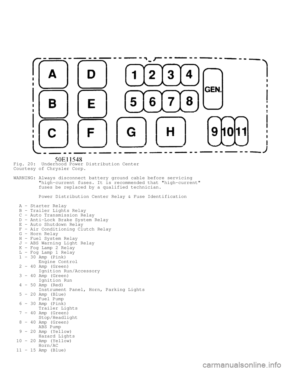
Fig. 20: Underhood Power Distribution Center
Courtesy of Chrysler Corp.
WARNING: Always disconnect battery ground cable before servicing
"high-current fuses. It is recommended that "high-current"
fuses be replaced by a qualified technician.
Power Distribution Center Relay & Fuse Identification
A - Starter Relay
B - Trailer Lights Relay
C - Auto Transmission Relay
D - Anti-Lock Brake System Relay
E - Auto Shutdown Relay
F - Air Conditioning Clutch Relay
G - Horn Relay
H - Fuel System Relay
J - ABS Warning Light Relay
K - Fog Lamp 2 Relay
L - Fog Lamp 1 Relay
1 - 30 Amp (Pink)
Engine Control
2 - 40 Amp (Green)
Ignition Run/Accessory
3 - 40 Amp (Green)
Ignition Run
4 - 50 Amp (Red)
Instrument Panel, Horn, Parking Lights
5 - 20 Amp (Blue)
Fuel Pump
6 - 30 Amp (Pink)
Trailer Lights
7 - 40 Amp (Green)
Stop/Headlight
8 - 40 Amp (Green)
ABS Pump
9 - 20 Amp (Yellow)
Hazard Lights
10 - 20 Amp (Yellow)
Horn/AC
11 - 15 Amp (Blue)
Page 927 of 1691

FUEL HEATER RELAY
Removal & Installation
Fuel heater relay is located in Power Distribution Center
(PDC). Check label under PDC cover for relay location. To install,
reverse removal procedure.
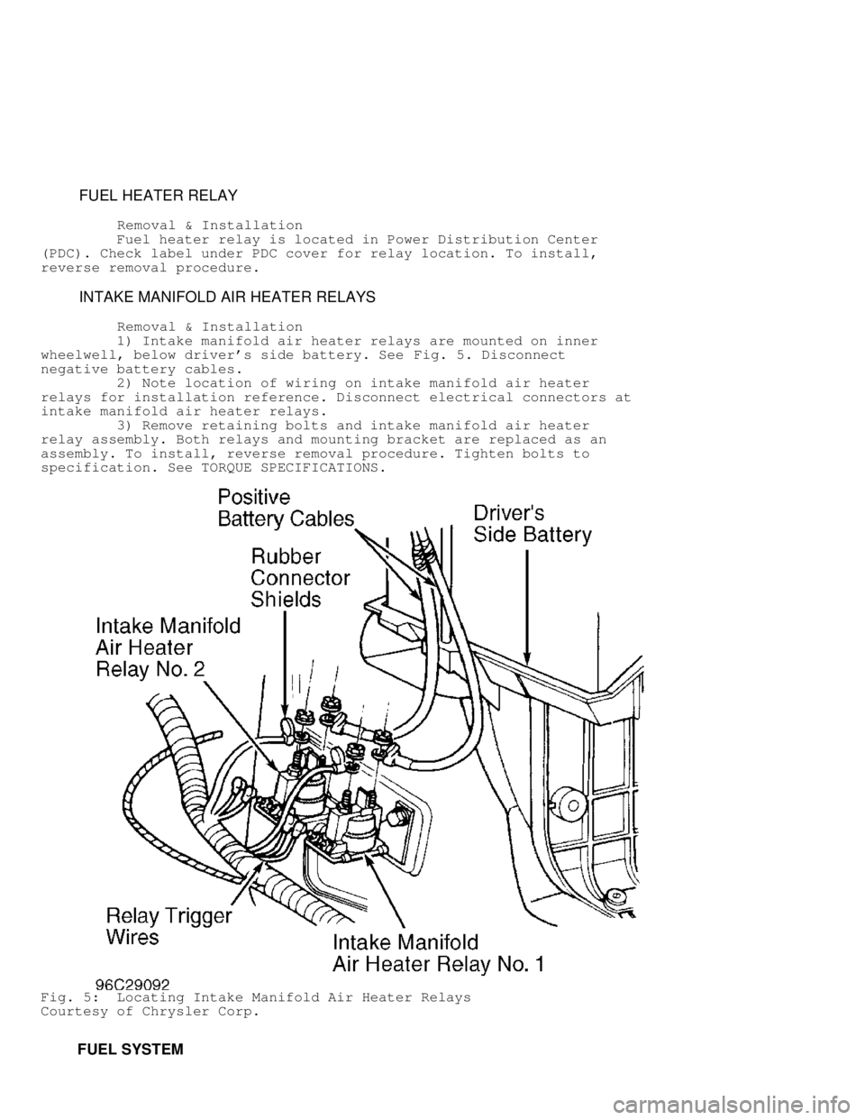
INTAKE MANIFOLD AIR HEATER RELAYS
Removal & Installation
1) Intake manifold air heater relays are mounted on inner
wheelwell, below driver's side battery. See Fig. 5. Disconnect
negative battery cables.
2) Note location of wiring on intake manifold air heater
relays for installation reference. Disconnect electrical connectors at
intake manifold air heater relays.
3) Remove retaining bolts and intake manifold air heater
relay assembly. Both relays and mounting bracket are replaced as an
assembly. To install, reverse removal procedure. Tighten bolts to
specification. See TORQUE SPECIFICATIONS.
Fig. 5: Locating Intake Manifold Air Heater Relays
Courtesy of Chrysler Corp.
FUEL SYSTEM
Page 928 of 1691

FUEL LINE DISCONNECT FITTINGS
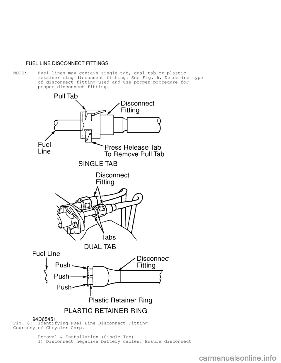
NOTE: Fuel lines may contain single tab, dual tab or plastic
retainer ring disconnect fitting. See Fig. 6. Determine type
of disconnect fitting used and use proper procedure for
proper disconnect fitting.
Fig. 6: Identifying Fuel Line Disconnect Fitting
Courtesy of Chrysler Corp.
Removal & Installation (Single Tab)
1) Disconnect negative battery cables. Ensure disconnect
Page 929 of 1691

fitting and fuel lines are clean. Note location of release tab and
pull tab on disconnect fitting. See Fig. 6.
CAUTION: Release tab must be pressed downward before removing pull tab
or pull tab will be damaged.
2) Press release tab downward. Use screwdriver to pry pull
tab upward until pull tab separates from disconnect fitting. Remove
disconnect fitting from fuel line. Inspect components for damage. If
disconnect fitting is damaged, entire assembly must be replaced, as
only pull tab can be replaced.
3) To install, ensure fuel line and disconnect fitting are
clean. Lubricate fuel line and disconnect fitting with engine oil.
Install disconnect fitting on fuel line until disconnect fitting
bottoms on fuel line.
4) Install NEW pull tab until pull tab locks in disconnect
fitting. DO NOT reuse old pull tab. Pull on fuel line and disconnect
fitting to ensure components are properly locked together. Reconnect
negative battery cables. Start engine and check for leaks.
Removal & Installation (Dual Tab)
1) Disconnect negative battery cables. Ensure disconnect
fitting and fuel lines are clean. Note location of tabs on disconnect
fitting. See Fig. 6.
2) Squeeze both tabs against disconnect fitting. Pull
disconnect fitting from fuel line. The plastic retainer will remain on
the fuel system component being serviced. The "O" rings and spacer
will remain in the disconnect fitting.
3) Inspect components for damage. If disconnect fitting is
damaged, entire assembly must be replaced. The only component that may
be replaced is the plastic retainer. If plastic retainer must be
removed from fuel system component, carefully release the plastic
retainer from the fuel system component using 2 screwdrivers. Inspect
plastic retainer for cracks or damage. Replace plastic retainer if
defective.
4) To install, ensure fuel line and disconnect fitting are
clean. Lubricate fuel line and disconnect fitting with engine oil.
Install disconnect fitting on fuel line until click sound is heard.
5) Pull on fuel line and disconnect fitting to ensure
components are properly locked together. Reconnect negative battery
cables. Start engine and check for leaks.
Removal & Installation (Plastic Retainer Ring)
1) Disconnect negative battery cables. Ensure disconnect
fitting and fuel lines are clean. Note location of plastic retainer
ring on disconnect fitting. See Fig. 6.
NOTE: Plastic retainer ring must be pressed evenly into disconnect
fitting. If plastic retainer is not even, it will be
difficult to remove disconnect fitting from fuel line.
2) Firmly push disconnect fitting toward the fuel line while
pushing plastic retainer ring evenly into disconnect fitting. With
plastic retainer ring fully depressed, pull disconnect fitting from
fuel line.
3) Inspect components for damage. If disconnect fitting is
damaged, entire assembly must be replaced.
4) To install, ensure fuel line and disconnect fitting are
clean. Lubricate fuel line and disconnect fitting with engine oil.
Install disconnect fitting on fuel line until click sound is heard.
5) Pull on fuel line and disconnect fitting to ensure
components are properly locked together. Reconnect negative battery
cables. Start engine and check for leaks.