1999 DODGE NEON power steering
[x] Cancel search: power steeringPage 158 of 1200
DRB DIAGNOSTIC SCAN TOOL USAGE
The diagnostics of the ITT Teves Mark 20 ABS sys-
tem used on this vehicle is performed using the DRB
scan tool. Refer to the diagnostics manual covering
the ITT Teves Mark 20 ABS system for the required
diagnostics ans testing procedures and the DRB oper-
ators manual for its proper operational information.
DRB DIAGNOSTIC CONNECTOR
On this vehicle, the diagnostics connector used for
diagnosing the Teves Mark 20 ABS system is located
under the steering column lower cover, to the left
side of the steering column (Fig. 14). The Teves Mark
20 ABS system uses the CCD connector which is
shared by other vehicle diagnostic systems such as
the powertrain control module and air bag.
ABS SYSTEM SELF DIAGNOSTICS
The ITT Teves Mark 20 ABS system is equipped
with a self diagnostic capability which may be used
to assist in the isolation of ABS faults. The features
of the self diagnostics system are described below.
START-UP CYCLE
The self diagnostic ABS start up cycle begins when
the ignition switch is turned to the on position. Elec-
trical checks are completed on ABS components, suchas the Controller, solenoid continuity, and the system
relay operation. During this check the Amber ABS
Warning Light is turned on for approximately 5 sec-
onds and the brake pedal may emit a popping sound
and move slightly when the solenoid valves are
checked.
DRIVE-OFF CYCLE
Further Functional testing is accomplished once
the vehicle is set in motion and reaches a speed of
about 20 kph (12 mph.). This cycle is performed only
once after each ignition on/off cycle.
²The pump/motor is activated briefly to verify
function. When the pump/motor is activated a whirl-
ing or buzzing sound may be heard by the driver,
which is normal when the pump/motor is running.
²The wheel speed sensor output is verified to be
within the correct operating range.
ONGOING TESTS
Other tests are performed on a continuous basis.
These include checks for solenoid continuity, wheel
speed sensor continuity and wheel speed sensor out-
put.
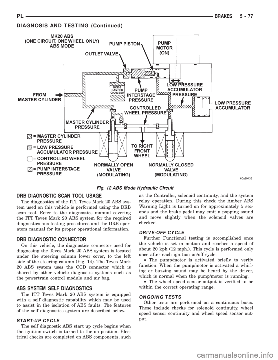
Fig. 12 ABS Mode Hydraulic Circuit
PLBRAKES 5 - 77
DIAGNOSIS AND TESTING (Continued)
Page 195 of 1200
During any reassembly procedures all pipe fittings
in water jacket, and waterbox require cleaning and
application of thread sealant for entire length of
threads.
ACCESSORY DRIVE BELTS
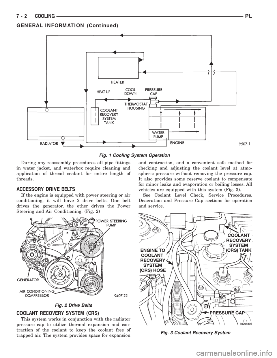
If the engine is equipped with power steering or air
conditioning, it will have 2 drive belts. One belt
drives the generator, the other drives the Power
Steering and Air Conditioning. (Fig. 2)
COOLANT RECOVERY SYSTEM (CRS)
This system works in conjunction with the radiator
pressure cap to utilize thermal expansion and con-
traction of the coolant to keep the coolant free of
trapped air. The system provides space for expansionand contraction, and a convenient safe method for
checking and adjusting the coolant level at atmo-
spheric pressure without removing the pressure cap.
It also provides some reserve coolant to compensate
for minor leaks and evaporation or boiling losses. All
vehicles are equipped with this system (Fig. 3).
See Coolant Level Check, Service Procedures.
Deaeration and Pressure Cap sections for operation
and service.
Fig. 1 Cooling System Operation
Fig. 2 Drive Belts
Fig. 3 Coolant Recovery System
7 - 2 COOLINGPL
GENERAL INFORMATION (Continued)
Page 210 of 1200
COOLING SYSTEMÐREFILLING
First clean system to remove old glycol, see Cooling
System Cleaning.
Fill system using antifreeze described in Coolant
section. Fill 50 percent of capacity with 100 percent
glycol. Then complete filling system with water.
Continue filling system until full, this provides bet-
ter heater performance.Be careful not to spill
coolant on drive belts or the generator.
Fill coolant reserve system to at least the FULL
mark with 50/50 solution. It may be necessary to add
coolant to the reserve tank after three or four warm-
up/cool down cycles to maintain coolant level between
the FULL and ADD marks; if any trapped air was
removed from the system.
REMOVAL AND INSTALLATION
WATER PUMP
REMOVAL
(1) Raise vehicle on a hoist. Remove right inner
splash shield.
(2) Remove accessory drive belts and power steer-
ing pump. Refer to Accessory Drive Belt service in
this section.
(3) Drain cooling system. Refer to Cooling System
Draining in this section.
(4) Support engine from the bottom and remove
right engine mount.
(5) Remove power steering pump bracket bolts and
set pump and bracket assembly aside. Power steering
lines do not need to be disconnected.
(6) Remove right engine mount bracket.
(7) Remove timing belt and timing belt tensioner.
Refer to Group 9, Engine for procedure.
(8) Remove camshaft sprockets and inner timing
belt cover. Refer to Group 9, Engine for procedure.(9) Remove water pump attaching screws to engine
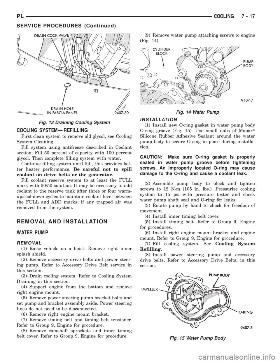
(Fig. 14).
INSTALLATION
(1) Install new O-ring gasket in water pump body
O-ring groove (Fig. 15). Use small dabs of Mopart
Silicone Rubber Adhesive Sealant around the water
pump body to secure O-ring in place during installa-
tion.
CAUTION: Make sure O-ring gasket is properly
seated in water pump groove before tightening
screws. An improperly located O-ring may cause
damage to the O-ring and cause a coolant leak.
(2) Assemble pump body to block and tighten
screws to 12 N´m (105 in. lbs.). Pressurize cooling
system to 15 psi with pressure tester and check
water pump shaft seal and O-ring for leaks.
(3) Rotate pump by hand to check for freedom of
movement.
(4) Install inner timing belt cover.
(5) Install timing belt. Refer to Group 9, Engine
for procedures.
(6) Install right engine mount bracket and engine
mount. Refer to Group 9, Engine for procedure.
(7) Fill cooling system. SeeCooling System
Refilling.
(8) Install power steering pump and accessory
drive belts, Refer to Accessory Drive Belts, in this
section.Fig. 13 Draining Cooling System
Fig. 14 Water Pump
Fig. 15 Water Pump Body
PLCOOLING 7 - 17
SERVICE PROCEDURES (Continued)
Page 214 of 1200
must be replaced withonlythe recommended part
for adequate strength, performance and safety.
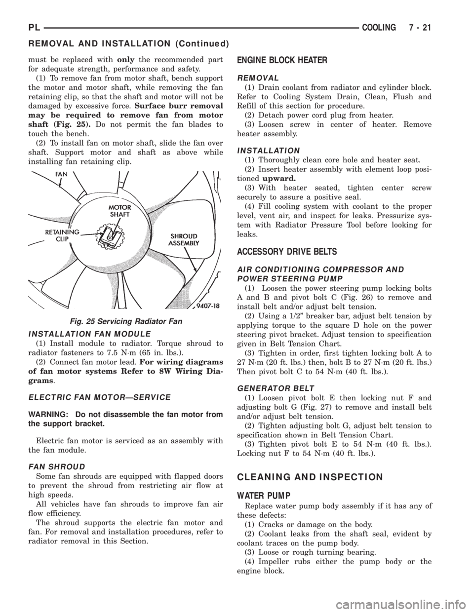
(1) To remove fan from motor shaft, bench support
the motor and motor shaft, while removing the fan
retaining clip, so that the shaft and motor will not be
damaged by excessive force.Surface burr removal
may be required to remove fan from motor
shaft (Fig. 25).Do not permit the fan blades to
touch the bench.
(2) To install fan on motor shaft, slide the fan over
shaft. Support motor and shaft as above while
installing fan retaining clip.
INSTALLATION FAN MODULE
(1) Install module to radiator. Torque shroud to
radiator fasteners to 7.5 N´m (65 in. lbs.).
(2) Connect fan motor lead.For wiring diagrams
of fan motor systems Refer to 8W Wiring Dia-
grams.
ELECTRIC FAN MOTORÐSERVICE
WARNING: Do not disassemble the fan motor from
the support bracket.
Electric fan motor is serviced as an assembly with
the fan module.
FAN SHROUD
Some fan shrouds are equipped with flapped doors
to prevent the shroud from restricting air flow at
high speeds.
All vehicles have fan shrouds to improve fan air
flow efficiency.
The shroud supports the electric fan motor and
fan. For removal and installation procedures, refer to
radiator removal in this Section.
ENGINE BLOCK HEATER
REMOVAL
(1) Drain coolant from radiator and cylinder block.
Refer to Cooling System Drain, Clean, Flush and
Refill of this section for procedure.
(2) Detach power cord plug from heater.
(3) Loosen screw in center of heater. Remove
heater assembly.
INSTALLATION
(1) Thoroughly clean core hole and heater seat.
(2) Insert heater assembly with element loop posi-
tionedupward.
(3) With heater seated, tighten center screw
securely to assure a positive seal.
(4) Fill cooling system with coolant to the proper
level, vent air, and inspect for leaks. Pressurize sys-
tem with Radiator Pressure Tool before looking for
leaks.
ACCESSORY DRIVE BELTS
AIR CONDITIONING COMPRESSOR AND
POWER STEERING PUMP
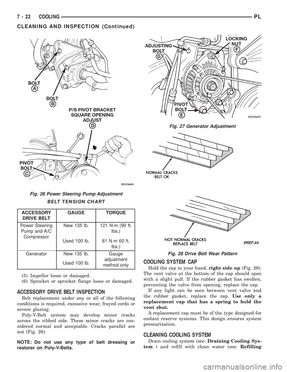
(1) Loosen the power steering pump locking bolts
A and B and pivot bolt C (Fig. 26) to remove and
install belt and/or adjust belt tension.
(2) Using a 1/2º breaker bar, adjust belt tension by
applying torque to the square D hole on the power
steering pivot bracket. Adjust tension to specification
given in Belt Tension Chart.
(3) Tighten in order, first tighten locking bolt A to
27 N´m (20 ft. lbs.) then, bolt B to 27 N´m (20 ft. lbs.)
Then pivot bolt C to 54 N´m (40 ft. lbs.).
GENERATOR BELT
(1) Loosen pivot bolt E then locking nut F and
adjusting bolt G (Fig. 27) to remove and install belt
and/or adjust belt tension.
(2) Tighten adjusting bolt G, adjust belt tension to
specification shown in Belt Tension Chart.
(3) Tighten pivot bolt E to 54 N´m (40 ft. lbs.).
Locking nut F to 54 N´m (40 ft. lbs.).
CLEANING AND INSPECTION
WATER PUMP
Replace water pump body assembly if it has any of
these defects:
(1) Cracks or damage on the body.
(2) Coolant leaks from the shaft seal, evident by
coolant traces on the pump body.
(3) Loose or rough turning bearing.
(4) Impeller rubs either the pump body or the
engine block.
Fig. 25 Servicing Radiator Fan
PLCOOLING 7 - 21
REMOVAL AND INSTALLATION (Continued)
Page 215 of 1200
(5) Impeller loose or damaged.
(6) Sprocket or sprocket flange loose or damaged.
ACCESSORY DRIVE BELT INSPECTION
Belt replacement under any or all of the following
conditions is required, excessive wear, frayed cords or
severe glazing.
Poly-V-Belt system may develop minor cracks
across the ribbed side. These minor cracks are con-
sidered normal and acceptable. Cracks parallel are
not (Fig. 28).
NOTE: Do not use any type of belt dressing or
restorer on Poly-V-Belts.
COOLING SYSTEM CAP
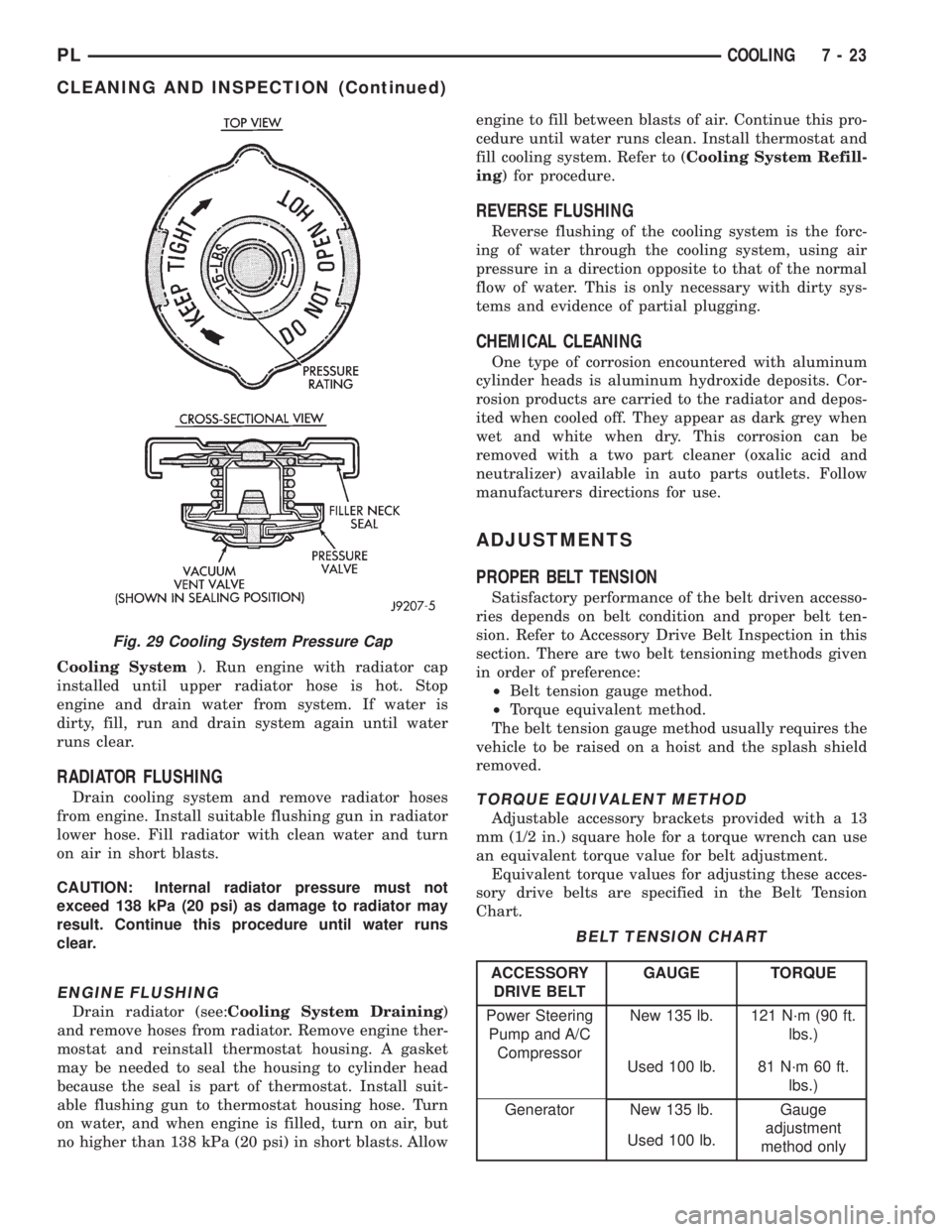
Hold the cap in your hand,right side up(Fig. 29).
The vent valve at the bottom of the cap should open
with a slight pull. If the rubber gasket has swollen,
preventing the valve from opening, replace the cap.
If any light can be seen between vent valve and
the rubber gasket, replace the cap.Use only a
replacement cap that has a spring to hold the
vent shut.
A replacement cap must be of the type designed for
coolant reserve systems. This design ensures system
pressurization.
CLEANING COOLING SYSTEM
Drain cooling system (see:Draining Cooling Sys-
tem) and refill with clean water (see:Refilling
Fig. 26 Power Steering Pump Adjustment
BELT TENSION CHART
ACCESSORY
DRIVE BELTGAUGE TORQUE
Power Steering
Pump and A/C
CompressorNew 135 lb. 121 N´m (90 ft.
lbs.)
Used 100 lb. 81 N´m 60 ft.
lbs.)
Generator New 135 lb. Gauge
adjustment
method only Used 100 lb.
Fig. 27 Generator Adjustment
Fig. 28 Drive Belt Wear Pattern
7 - 22 COOLINGPL
CLEANING AND INSPECTION (Continued)
Page 216 of 1200
Cooling System). Run engine with radiator cap
installed until upper radiator hose is hot. Stop
engine and drain water from system. If water is
dirty, fill, run and drain system again until water
runs clear.
RADIATOR FLUSHING
Drain cooling system and remove radiator hoses
from engine. Install suitable flushing gun in radiator
lower hose. Fill radiator with clean water and turn
on air in short blasts.
CAUTION: Internal radiator pressure must not
exceed 138 kPa (20 psi) as damage to radiator may
result. Continue this procedure until water runs
clear.
ENGINE FLUSHING
Drain radiator (see:Cooling System Draining)
and remove hoses from radiator. Remove engine ther-
mostat and reinstall thermostat housing. A gasket
may be needed to seal the housing to cylinder head
because the seal is part of thermostat. Install suit-
able flushing gun to thermostat housing hose. Turn
on water, and when engine is filled, turn on air, but
no higher than 138 kPa (20 psi) in short blasts. Allowengine to fill between blasts of air. Continue this pro-
cedure until water runs clean. Install thermostat and
fill cooling system. Refer to (Cooling System Refill-
ing) for procedure.
REVERSE FLUSHING
Reverse flushing of the cooling system is the forc-
ing of water through the cooling system, using air
pressure in a direction opposite to that of the normal
flow of water. This is only necessary with dirty sys-
tems and evidence of partial plugging.
CHEMICAL CLEANING
One type of corrosion encountered with aluminum
cylinder heads is aluminum hydroxide deposits. Cor-
rosion products are carried to the radiator and depos-
ited when cooled off. They appear as dark grey when
wet and white when dry. This corrosion can be
removed with a two part cleaner (oxalic acid and
neutralizer) available in auto parts outlets. Follow
manufacturers directions for use.
ADJUSTMENTS
PROPER BELT TENSION
Satisfactory performance of the belt driven accesso-
ries depends on belt condition and proper belt ten-
sion. Refer to Accessory Drive Belt Inspection in this
section. There are two belt tensioning methods given
in order of preference:
²Belt tension gauge method.
²Torque equivalent method.
The belt tension gauge method usually requires the
vehicle to be raised on a hoist and the splash shield
removed.
TORQUE EQUIVALENT METHOD
Adjustable accessory brackets provided with a 13
mm (1/2 in.) square hole for a torque wrench can use
an equivalent torque value for belt adjustment.
Equivalent torque values for adjusting these acces-
sory drive belts are specified in the Belt Tension
Chart.
Fig. 29 Cooling System Pressure Cap
BELT TENSION CHART
ACCESSORY
DRIVE BELTGAUGE TORQUE
Power Steering
Pump and A/C
CompressorNew 135 lb. 121 N´m (90 ft.
lbs.)
Used 100 lb. 81 N´m 60 ft.
lbs.)
Generator New 135 lb. Gauge
adjustment
method only Used 100 lb.
PLCOOLING 7 - 23
CLEANING AND INSPECTION (Continued)
Page 217 of 1200
BELT TENSION GAUGE METHOD
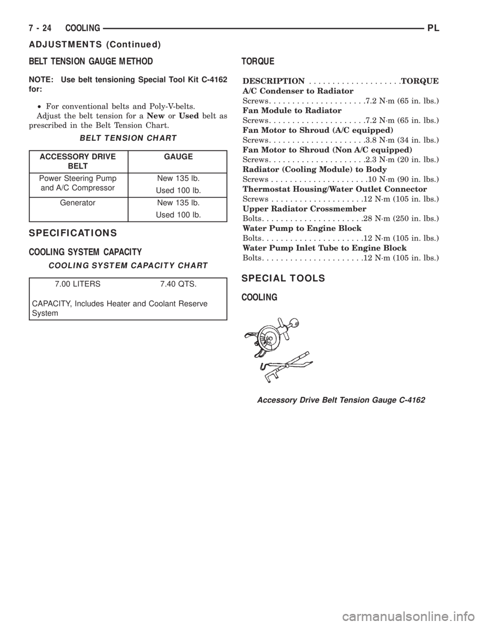
NOTE: Use belt tensioning Special Tool Kit C-4162
for:
²For conventional belts and Poly-V-belts.
Adjust the belt tension for aNeworUsedbelt as
prescribed in the Belt Tension Chart.
SPECIFICATIONS
COOLING SYSTEM CAPACITYTORQUE
DESCRIPTION....................TORQUE
A/C Condenser to Radiator
Screws.....................7.2 N´m (65 in. lbs.)
Fan Module to Radiator
Screws.....................7.2 N´m (65 in. lbs.)
Fan Motor to Shroud (A/C equipped)
Screws.....................3.8 N´m (34 in. lbs.)
Fan Motor to Shroud (Non A/C equipped)
Screws.....................2.3 N´m (20 in. lbs.)
Radiator (Cooling Module) to Body
Screws.....................10N´m(90in.lbs.)
Thermostat Housing/Water Outlet Connector
Screws....................12N´m(105 in. lbs.)
Upper Radiator Crossmember
Bolts......................28N´m(250 in. lbs.)
Water Pump to Engine Block
Bolts......................12N´m(105 in. lbs.)
Water Pump Inlet Tube to Engine Block
Bolts......................12N´m(105 in. lbs.)
SPECIAL TOOLS
COOLING
BELT TENSION CHART
ACCESSORY DRIVE
BELTGAUGE
Power Steering Pump
and A/C CompressorNew 135 lb.
Used 100 lb.
Generator New 135 lb.
Used 100 lb.
COOLING SYSTEM CAPACITY CHART
7.00 LITERS 7.40 QTS.
CAPACITY, Includes Heater and Coolant Reserve
System
Accessory Drive Belt Tension Gauge C-4162
7 - 24 COOLINGPL
ADJUSTMENTS (Continued)
Page 294 of 1200
HORNS
CONTENTS
page page
DESCRIPTION AND OPERATION
INTRODUCTION......................... 1
DIAGNOSIS AND TESTING
HORN RELAY........................... 2
HORN SWITCH.......................... 2
HORN................................. 1SYSTEM TEST.......................... 2
REMOVAL AND INSTALLATION
HORN RELAY........................... 4
HORN SWITCHES........................ 4
HORN................................. 4
DESCRIPTION AND OPERATION
INTRODUCTION
WARNING: ON VEHICLES EQUIPPED WITH AIR-
BAG, SEE GROUP 8M, RESTRAINT SYSTEMS FOR
STEERING WHEEL OR COLUMN REMOVAL PROCE-
DURES.
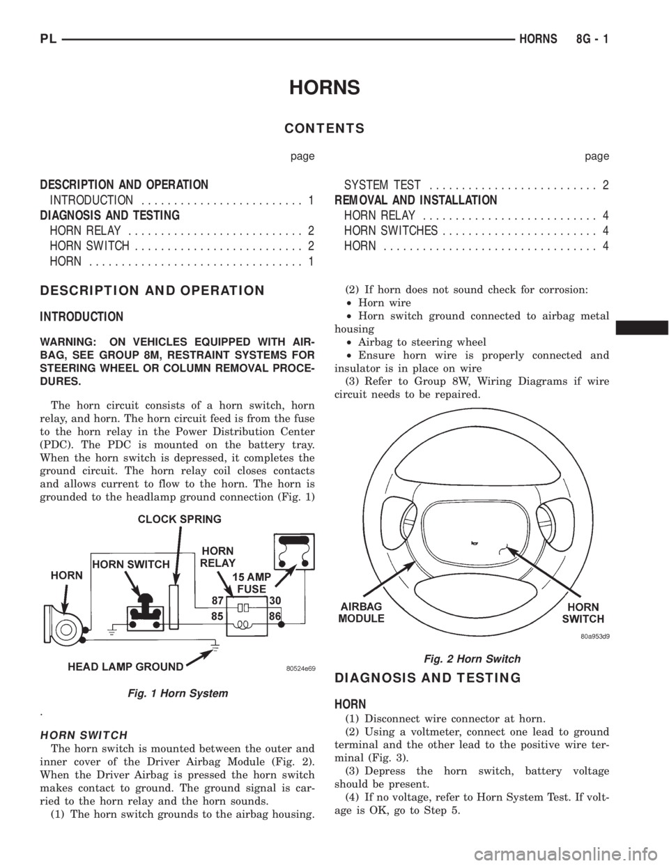
The horn circuit consists of a horn switch, horn
relay, and horn. The horn circuit feed is from the fuse
to the horn relay in the Power Distribution Center
(PDC). The PDC is mounted on the battery tray.
When the horn switch is depressed, it completes the
ground circuit. The horn relay coil closes contacts
and allows current to flow to the horn. The horn is
grounded to the headlamp ground connection (Fig. 1)
.
HORN SWITCH
The horn switch is mounted between the outer and
inner cover of the Driver Airbag Module (Fig. 2).
When the Driver Airbag is pressed the horn switch
makes contact to ground. The ground signal is car-
ried to the horn relay and the horn sounds.
(1) The horn switch grounds to the airbag housing.(2) If horn does not sound check for corrosion:
²Horn wire
²Horn switch ground connected to airbag metal
housing
²Airbag to steering wheel
²Ensure horn wire is properly connected and
insulator is in place on wire
(3) Refer to Group 8W, Wiring Diagrams if wire
circuit needs to be repaired.
DIAGNOSIS AND TESTING
HORN
(1) Disconnect wire connector at horn.
(2) Using a voltmeter, connect one lead to ground
terminal and the other lead to the positive wire ter-
minal (Fig. 3).
(3) Depress the horn switch, battery voltage
should be present.
(4) If no voltage, refer to Horn System Test. If volt-
age is OK, go to Step 5.
Fig. 1 Horn System
Fig. 2 Horn Switch
PLHORNS 8G - 1